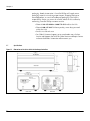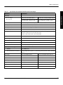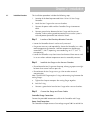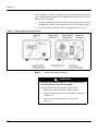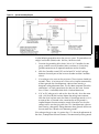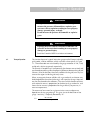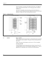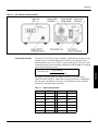
1
Series 342 Granville-Phillips® Series 342 & 343 Ion Gauge Controllers Instruction Manual Instruction manual part number 342026 Revision C - January 2013 Instruction manual part number 342026 Series 342 Granville-Phillips® Series 342 & 343 Ion Gauge Controllers This Instruction Manual is for use with the following Granville-Phillips Series 342 Controllers: 20342070, 342017, 342022, 343011 Customer Service/Support For customer service within USA, 8 AM to 5 PM Mountain Time Zone, weekdays excluding holidays: Granville-Phillips 6450 Dry Creek Parkway Longmont, CO 80503 USA Phone: +1-800-776-6543 Phone: +1-303-652-4400 FAX: +1-303-652-2844 Email: [email protected] Brooks Automation, Inc. 15 Elizabeth Drive Chelmsford, MA 01824 USA Phone: +1-978-262-2400 For customer service, 24 hours per day, 7 days per week, every day of the year including holidays within the USA: Phone: +1-800-367-4887 www.brooks.com Instruction Manual © 1994 - 2013 Brooks Automation, Inc. All rights reserved. Granville-Phillips® and Mini-Ion® are registered trademarks of Brooks Automation, Inc. All other trademarks and registered trademarks are the properties of their respective owners. Granville-Phillips® Series 342 & 343 Ion Gauge Controllers with Digital Display Catalog numbers for Series 342 & 343 Ion Gauge Controllers Ion Gauge Controller - with digital display: 20342070 Ion Gauge Controller - with digital display: 342017 Ion Gauge Controller - with digital display: 342022 Ion Gauge Controller - with digital display: 343011 Catalog numbers for Series 342 Triode Ion Gauges Ion Gauge with 0.75 inch Kovar 342003 Ion Gauge with NW16KF Stainless Steel flange 342004 Ion Gauge with NW16KF Stainless Steel flange mounted on a 90o elbow 342015 Catalog numbers for Series 343 Bayard-Alpert Ion Gauges Ion Gauge with 0.75 inch Kovar 343001 Ion Gauge with NW16KF Stainless Steel flange 343002 Ion Gauge with 1-5/16 inch non-rotatable ConFlat-type flange (for readings below 1 x 10⁻⁷ Torr) 342003 Ion Gauge pumped down and sealed for testing 343013 Ion Gauge Cables for Series 342 & 343 Controllers Cable: 1 meter long (3.2 feet) 342023 Cable: 2 meters long (6.5 feet) 342024 Cable: 3 meters long (9.8 feet) 342025 Table of Contents Chapter 1 Safety & Introduction . . . . . . . . . . . . . . . . . . . . . . . . . . . . . . . . . 1.1 1.2 1.3 1.4 1.5 1.6 1.7 Chapter 2 Installation 2.1 Step 1 Step 2 Step 3 Step 4 Chapter 3 .......................................... Installation Procedure . . . . . . . . . . . . . . . . . . . . . . . . . . . . . Location of the Benchtop Mounted Controller . . . . . . . . . . Install the Ion Gauge on the Vacuum Chamber . . . . . . . . . . Connect the Gauge and Power Cables . . . . . . . . . . . . . . . . System Grounding Procedure . . . . . . . . . . . . . . . . . . . . . . . Operation 3.1 3.2 Chapter 4 Caution and Warning Statements . . . . . . . . . . . . . . . . . . . . Damage Requiring Service . . . . . . . . . . . . . . . . . . . . . . . . . Implosion/Explosion Conditions . . . . . . . . . . . . . . . . . . . . . Proper Grounding . . . . . . . . . . . . . . . . . . . . . . . . . . . . . . . . Warranty Information . . . . . . . . . . . . . . . . . . . . . . . . . . . . . Service Guidelines . . . . . . . . . . . . . . . . . . . . . . . . . . . . . . . Specifications . . . . . . . . . . . . . . . . . . . . . . . . . . . . . . . . . . . ........................................... Theory of Operation . . . . . . . . . . . . . . . . . . . . . . . . . . . . . . Operation . . . . . . . . . . . . . . . . . . . . . . . . . . . . . . . . . . . . . . Gas Sensitivity Correction . . . . . . . . . . . . . . . . . . . . . . . . . . 7 7 9 11 13 13 13 14 17 17 17 17 17 18 21 21 22 23 Service & Maintenance . . . . . . . . . . . . . . . . . . . . . . . . . . . . . . . 25 4.1 4.2 4.3 4.4 Service Guidelines . . . . . . . . . . . . . . . . . . . . . . . . . . . . . . . Damage Requiring Service . . . . . . . . . . . . . . . . . . . . . . . . . Troubleshooting . . . . . . . . . . . . . . . . . . . . . . . . . . . . . . . . . Ion Gauge Continuity Test . . . . . . . . . . . . . . . . . . . . . . . . . 25 25 26 28 Index . . . . . . . . . . . . . . . . . . . . . . . . . . . . . . . . . . . . . . . . . . . . . . . . . . . . . . . . . . . . . . . . . . . . . . . . . . . . . 31 Series 342/343 Instruction Manual - 342026 - Rev C 5 Table of Contents 6 Series 342/343 Instruction Manual - 342026 - Rev C Chapter 1 Safety & Introduction The instructions given in this user manual explain how to install, operate, and maintain the Granville-Phillips® Series 342 & 343 Ion Gauge Controllers and Ion Gauges. Caution and Warning Statements This manual contains Caution and Warning statements with which you MUST comply to prevent inaccurate measurement, property damage, or personal injury. Safety Installation & Introduction 1.1 CAUTION Caution statements alert you to hazards or unsafe practices that could result in inaccurate measurement, minor personal injury, or property damage. Operation Overview Each caution statement explains what you must do to prevent or avoid the potential result of the specified hazard or unsafe practice. WARNING Warning statements alert you to hazards or unsafe practices that could result in severe property damage or personal injury due to electrical shock, fire, or explosion. Each caution or warning statement explains: The specific hazard that you must prevent or unsafe practice that you must avoid, b. The potential result of your failure to prevent the specified hazard or avoid the unsafe practice, and c. What you must do to prevent the specified hazardous result. 7 Maintenance Series 342/343 Instruction Manual - 342026 - Rev C RS-232 Operation a. Analog Operation Each warning statement explains what you must do to prevent or avoid the potential result of the specified hazard or unsafe practice. Chapter 1 CAUTION These safety alert symbols in this manual or on the Product rear panel, mean caution − personal safety, property damage, or danger from electric shock. Read these instructions carefully. In these instructions the word “product” refers to the Series 342 or 343 Ion Gauge Controller and all of its approved parts and accessories. NOTE: These instructions do not and cannot provide for every contingency that may arise in connection with the installation, operation, or maintenance of this product. If you require further assistance, contact Brooks Automation, Inc. at the address on the title page of this manual. This product offers safe service provided it is installed, operated, and serviced in strict accordance with these safety instructions. WARNING Failure to comply with these instructions may result in serious personal injury, including death, or property damage. NOTE: These safety precautions must be observed during all phases of operation, installation, and service of this product. Failure to comply with these precautions or with specific warnings elsewhere in this manual violates safety standards of design, manufacture, and intended use of the instrument. Brooks Automation, Inc. disclaims all liability for the customer's failure to comply with these requirements. WARNING To reduce the risk of fire or electric shock, do not expose this product to rain or moisture. 8 Series 342/343 Instruction Manual - 342026 - Rev C Safety & Introduction WARNING Safety Installation & Introduction Be aware that when high voltage is present in any vacuum system, a life threatening electrical shock hazard may exist unless all exposed conductors are maintained at earth ground. This hazard is not peculiar to this product. WARNING Operation Overview Be aware that an electrical discharge through a gas may couple dangerous high voltage directly to an ungrounded conductor almost as effectively as would a copper wire connection. A person may be seriously injured or even killed by merely touching an exposed ungrounded conductor at high potential. This hazard is not unique to this product. CAUTION 1.2 Damage Requiring Service Analog Operation Objects and Liquid Entry − Never push objects of any kind into this product through openings as they may touch dangerous voltage points or short out parts that could result in a fire or electric shock. Be careful not to spill liquid of any kind onto the products. Disconnect the product from all power sources and refer servicing to Qualified Service Personnel under the following conditions: When any cable or plug is damaged. b. If any liquid has been spilled onto, or objects have fallen into, the product. c. If the product has been exposed to rain or water. d. If the product does not operate normally even if you follow the operating instructions. Adjust only those controls that are covered by the operation instructions. Improper adjustment of other controls may result in damage and will often require extensive work by a qualified technician to restore the product to its normal operation. e. If the product has been dropped or the enclosure has been damaged. f. When the product exhibits a distinct change in performance. This indicates a need for service. 9 Maintenance Series 342/343 Instruction Manual - 342026 - Rev C RS-232 Operation a. The service and repair information in this manual is for the use of Qualified Service Personnel. To avoid electrical shock, do not perform any procedures in this manual or perform any servicing on this product unless you are qualified to do so. CAUTION Replacement Parts − When replacement parts are required, be certain to use the replacement parts that are specified by Brooks Automation, Inc. or that have the same characteristics as the original parts. Unauthorized substitutions may result in fire, electric shock or other hazards. Return the product to a service facility designated by Brooks Automation, Inc. for service and repair to ensure that safety features are maintained. Do not use this product if it has unauthorized modifications. CAUTION Safety Check − Upon completion of any service or repairs to this product, ask the Qualified Service Person to perform safety checks to determine that the product is in safe operating order. 10 Series 342/343 Instruction Manual - 342026 - Rev C Safety & Introduction 1.3 Implosion/Explosion Conditions WARNING Safety Installation & Introduction Do not operate in an explosive atmosphere. Do not operate the product in the presence of flammable gases or fumes. Operation of any electrical instrument in such an environment constitutes a definite safety hazard. Do not use the product to measure the pressure of explosive or combustible gases or gas mixtures. Danger of explosion or inadvertent venting to atmosphere exists on all vacuum systems which incorporate gas sources or involve processes capable of pressurizing the system above safe limits. Operation Overview WARNING The fumes from solvents such as trichloroethylene, perchloroethylene, toluene, and acetone can be dangerous to health if inhaled. Use only in well ventilated areas exhausted to the outdoors. Acetone and toluene are highly flammable and should not be used near an open flame or energized electrical equipment. Analog Operation CAUTION Install suitable devices that will limit the pressure to the level that the vacuum system can safely withstand. In addition, install suitable pressure relief valves or rupture disks that will release pressure at a level considerably below the pressure that the system can safely withstand. RS-232 Operation CAUTION If accurate conversion data is not used, or is improperly used, a potential overpressure explosion hazard can be created under certain conditions. A pressure relief valve should be installed in the system if the possibility of exceeding 1000 Torr (1333 mbar) exists. Suppliers of pressure relief valves and pressure relief disks can be located via an internet search, and are listed in the Thomas Register under “Valves, Relief” and “Discs, Rupture.” 11 Maintenance Series 342/343 Instruction Manual - 342026 - Rev C Chapter 1 Confirm that these safety devices are properly installed before installing the product. In addition, check that: a. The proper gas cylinders are installed, b. Gas cylinder valve positions are correct on manual systems, and c. The automation is correct on automated gas delivery system Vacuum gauges with compression fittings may be forcefully ejected if the vacuum system is pressurized. WARNING Using the N2 calibration to pressurize a vacuum system above about 1 Torr with certain other gases can cause dangerously high pressures which may cause explosion of the system. It is the installer's responsibility to ensure that the automatic signals provided by the product are always used in a safe manner. Where an equipment malfunction could cause a hazardous situation, always provide for fail-safe operation. As an example, in an automatic backfill operation where a malfunction might cause high internal pressures, provide an appropriate pressure relief device. 12 Series 342/343 Instruction Manual - 342026 - Rev C Safety & Introduction 1.4 Proper Grounding WARNING Safety Installation & Introduction All components of a vacuum system used with this or any similar high voltage product must be maintained at Earth ground for safe operation. The power cord of this product must be connected only to a properly grounded outlet. Be aware, however, that grounding this product does not guarantee that other components of the vacuum system are maintained at Earth ground. Operation Overview Complying with the usual warning to connect the power cable only to a properly grounded outlet is necessary but not sufficient for safe operation of a vacuum system with this or any similar high voltage producing product. Verify that the vacuum port to which the Ion Gauge is mounted is electrically grounded. It is essential for personnel safety as well as proper operation that the envelope of the gauge be connected to a facility ground. Warranty Information Brooks Automation, Inc. provides an eighteen (18) month warranty from the date of shipment for new Granville-Phillips Controllers. The Brooks Automation, Inc. General Terms and Conditions of Sale provides the complete and exclusive warranty for Brooks Automation products. This document may be located on our web site at www.brooks.com, or may be obtained by contacting a Brooks Automation Customer Service Representative. 1.6 Service Guidelines Some minor problems are readily corrected on site. If the product requires service, please contact our Customer Service Department at 303-652-4400 for troubleshooting help over the phone. RS-232 Operation If the module must be returned to the factory for service, request a Return Authorization (RA) from Brooks Automation / Granville-Phillips. Do not return products without first obtaining an RA. In some cases a hazardous materials document may be required. The Brooks Automation / Granville-Phillips Customer Service Representative will advise you if the hazardous materials document is required. Analog Operation 1.5 When returning equipment to Brooks Automation / Granville-Phillips, be sure to package the products to prevent shipping damage. Circuit boards and modules separated from the controller chassis must be handled using proper anti-static protection methods and must be packaged in anti-static 13 Maintenance Series 342/343 Instruction Manual - 342026 - Rev C Chapter 1 packaging. Brooks Automation / Granville-Phillips will supply return packaging materials at no charge upon request. Shipping damage on returned products as a result of inadequate packaging is the Buyer's responsibility. Before you return the module, obtain an RA number by contacting Granville-Phillips customer service: • Phone 1-303-652-4400 or 1-800-776-6543 within the USA. • Phone 1-800-367-4887 24 hours per day, seven days per week within the USA. • Email [email protected] • For Global Customer Support, go to www.brooks.com, click on Service and Support, then click on Global Service and Repair Centers to locate the Brooks Automation office nearest you. 1.7 Specifications Figure 1-1 Dimensions of the Series 342 & 343 Ion Gauge Controllers 14 Series 342/343 Instruction Manual - 342026 - Rev C Safety & Introduction Table 1-1 Specifications of the Ion Gauge Controllers and Vacuum Gauges Parameter Specification Pressure Range (for N2 or Air) With Series 342 Triode style IG With Series 343 Bayard-Alpert style IG 10-6 Less than 5 x 10⁻⁸ Torr to 5 x 10⁻³ Torr using 2.0 mAdc emission current 10-2 Torr to 5 x Torr Less than 1 x using 1.0 mAdc emission current ± 5% of reading at ambient temperature of 25 0C (77 0F) Display Units Torr Display Resolution Scientific notation, 2 significant digits Display Update Time 0.5 sec. Overpressure Protection The ion gauge is turned OFF if the pressure rises above the upper pressure limit. 50 mTorr (5x10⁻²) for the 342 Triode ion gauge 5 mTorr (5x10⁻³ Torr) for the 343 BA ion gauge Operation Overview Accuracy Safety Installation & Introduction Controller Electrical Voltage 100 - 240 VAC ± 10%, 50 - 60 Hz Power 25 W Max Fuse Rating .50 Amp, Buss MDA 1/2 or Littlefuse 326.500 Enviromental Conditions Indoor Use Only 0 0C to 40 0C (32 0F - 104 0F) Altitude Up to 2000 meters Maximum Relative Humidity 80% for temperatures up to 31 0C decreasing linearly to 50% relative humidity at 40 0C. Ion Gauge Series 343 Bayard-Albert style IG Sensitivity 6.2/Torr nominal 5.2/Torr nominal Emission Current 1.0 mAdc 2.0 mAdc Collector Potential 0 Vdc 0 Vdc Grid Potential +180 Vdc +180 Vdc Filament Potential +30 Vdc +30 Vdc Degas None None 15 Maintenance Series 342/343 Instruction Manual - 342026 - Rev C RS-232 Operation Series 342 Triode style IG Analog Operation Temperature Range Chapter 1 Notes: 16 Series 342/343 Instruction Manual - 342026 - Rev C 2.1 Installation Procedure Before You Begin Chapter 2 Installation The installation procedure includes the following steps: 1. Location of the benchtop mounted Series 342 or 343 Ion Gauge Controller. 2. Attach the Ion Gauge to the vacuum chamber. 3. Connect the power cable and the Controller/Gauge interconnect cable. 4. Connect ground wires between the Ion Gauge and the vacuum chamber, and any other ground connections to assure the system is safe and protects personnel from electrical shock. Step 1 Location of the Benchtop Mounted Controller • For greatest accuracy and repeatability, locate the Controller in a stable, room-temperature environment. Ambient temperature should never exceed 40 0C (104 0F) operating, non-condensing, or 85 0C (185 0F) non-operating. • Locate the Controller away from internal and external heat sources and in an area where ambient temperature remains reasonably constant. Step 2 Operation Installation Overview • Locate the Controller where it can be easily accessed. Install the Ion Gauge on the Vacuum Chamber • Do not locate the Ion Gauge near a gas inlet or other source of contamination. Analog Operation • Do not locate the Ion Gauge near the pump, where gauge pressure might be lower than normal vacuum pressure. Note: The NW16KF flange requires O-rings and centering rings between the mating flanges. a. Tighten the clamp to compress the mating flanges together. Seal the O-ring. c. Connect a ground wire from the Ion Gauge to the vacuum chamber. Step 3 Connect the Gauge and Power Cables Controller/Gauge Connection: RS-232 Operation b. Connect the provided interconnect cable to the Controller and Gauge. Power Cord Connection: The Controller will operate over a line voltage range of 100 Vac to 240 Vac 17 Maintenance Series 342/343 Instruction Manual - 342026 - Rev C Chapter 2 ±10%, 50-60 Hz. All that is required is that a line cord be selected to match your available power receptacle to the power input connector located on the rear of the Controller. Figure 2-1 a. Connect a ground wire from the ground connection on the rear of the Controller to a known system ground. See System Grounding, Step 4. b. Connect the power cable, but do NOT apply power at this time. Micro-Ion Gauge Controller Connections Step 4 System Grounding Procedure WARNING Improper grounding could cause severe product failure or personal injury from electrical shock. Follow ground network requirements for the facility. 18 • Maintain all exposed conductors at Earth ground. • Ground the Ion Gauge to the vacuum chamber as illustrated in Figure 2−2. • Connect the system ground wires as illustrated in Figure 2−2. Series 342/343 Instruction Manual - 342026 - Rev C Figure 2-2 System Grounding Diagram 2. With the Controller turned OFF, test for both DC and AC voltages between the metal parts of the vacuum chamber and the Controller chassis. 3. If no voltages exist, measure the resistance. The resistance should not exceed 2 Ohms. A resistance of 2 Ohms or less implies commonality of these grounds that should prevent a plasma from creating a dangerous voltage between them. This test does not prove that either connection is at Earth ground, only that they are the same. If more than 2 Ohms is indicated, check with a licensed electrician. 4. If AC or DC voltages exist and are less than 10 volts, shunt the meter with a 10 Ohm/10 Watt resistor. Repeat the voltage measurement. With the shunt in place across the meter, if the voltage remains at 83% or more of the un-shunted value, commonality of the grounds is implied. Repeat the measurements several times to be sure that the voltage ratio is not changing with time. This should prevent a plasma from creating a dangerous voltage between these grounds. Make sure that no more than 10 volts exists between grounds. RS-232 Operation Examine the grounding of the Series 342 or 343 Controller, the ion gauge, and the vacuum chamber. Make sure there is a heavy duty ground connection to all exposed conductors on the chamber. Analog Operation 1. Operation Installation Overview Use the following procedure to test the vacuum system. This procedure uses a digital multimeter (DMM) and a 10 Ohm, 10 Watt resistor. Before You Begin Installation If the voltage change in step 4 is greater than 17% due to the placement of the shunt, it complicates the measurement. The commonality of the grounds 19 Maintenance Series 342/343 Instruction Manual - 342026 - Rev C Chapter 2 may be satisfactory and the coupling poor, or the commonality could be poor. Be sure to check the electrical continuity between these two ground systems. 20 Series 342/343 Instruction Manual - 342026 - Rev C Before You Begin Chapter 3 Operation WARNING Installation Using the Series 342/343 Controller and Ion Gauge to measure the pressure of flammable or explosive gases can cause a fire or explosion resulting in severe property damage, personal injury, or death. Do not measure the pressure of flammable or explosive gases. WARNING Exposing the Series 342/343 Controller to moisture can cause fire or electrical shock resulting in severe property damage or personal injury. Install the Controller ONLY in an indoor environment. 3.1 Theory of Operation The filament is heated to such a temperature that electrons are emitted, and accelerated toward the grid by the potential difference between the grid and filament. All of the electrons eventually collide with the grid, but many first traverse the region inside the grid many times. The amount of ion current for a given emission current and pressure depends on the ion gauge design. This gives rise to the definition of ion gauge “sensitivity”, frequently denoted by “K”: ion current K= (emission current x pressure) 21 Maintenance Series 342/343 Instruction Manual - 342026 - Rev C RS-232 Operation When an energetic electron collides with a gas molecule an electron may be dislodged from the molecule leaving it with a positive charge. Most ions are then accelerated to the collectors. The rate at which electron collisions with molecules occur is proportional to the density of gas molecules, and hence the ion current is proportional to the gas density (or pressure, at constant temperature). Analog Operation Operation The functional parts of a typical ionization gauge are the filament (cathode), grid (anode), and ion collector, which are shown schematically in Figure 3-1. These electrodes are maintained by the gauge controller at +30, +180, and 0 volts, relative to ground, respectively. Chapter 3 The Ion Gauge has a sensitivity of 6.2/Torr for the Series 342 Triode ion gauge, and 5.2/Torr for the Series 343 B-A ion gauge, when used with nitrogen or air. The 342/343 Controller varies the heating current to the filament to maintain a constant electron emission, and measures the ion current to the collector. The pressure is then calculated from these data. Figure 3-1 Ion Gauge Illustration 3.2 Operation Power ON/OFF Depress the top half of the rocker power switch located on the rear panel to turn ON power to the Controller. The green LED on the front panel will illuminate. Depress the lower half of the power switch to turn OFF the Controller. Ion Gauge ON/OFF Use the pushbutton on the front panel to turn the Ion Gauge ON or OFF. The digital display will turn ON immediately and display 9.9+9. After an approximate 6 second delay the actual pressure will be displayed. 22 Series 342/343 Instruction Manual - 342026 - Rev C Figure 3-2 Series 342/343 Ion Gauge Controller Before You Begin Operation Installation Gas Sensitivity Correction The Series 342/343 Ion Gauge Controller is calibrated to read pressure for nitrogen or air. If used with other gases, the pressure reading must be corrected for the gas in use. Table 3-1 gives some typical sensitivity ratios. To correct the pressure curve reading, divide the indicated pressure reading by the relative sensitivity ratio. Gauge Reading Relative Sensitivity (RX) Ion gauge sensitivity ratios (RX) shown in Table 3-1 are from NASA Technical Note TND5285, “Ionization Gauge Sensitivities as Reported in the Literature,” by Robert L. Summers, Lewis Research Center, National Aeronautics and Space Administration. Table 3-1 Gas Relative Gas Sensitivities Gas RX He 0.18 H2O 1.12 0.30 NO 1.16 D2 0.35 Ar 1.29 H2 0.46 CO2 1.42 N2 1.00 Kr 1.94 Air 1.00 SF6 2.5 O2 1.01 Xe 2.87 RS-232 Operation RX Ne 23 Maintenance Series 342/343 Instruction Manual - 342026 - Rev C Analog Operation Operation True Pressure = Chapter 3 Notes: 24 Series 342/343 Instruction Manual - 342026 - Rev C 4.1 Service Guidelines Before You Begin Chapter 4 Service & Maintenance If a qualified service person makes repairs at the component level, repairs properly made with equivalent electronic parts and rosin core solder do not void the warranty. If the product requires service, contact Brooks Automation / Granville-Phillips Customer Service Department at 1-800-776-6543 for troubleshooting help over the phone. Other phone numbers are published on the front and back covers, and below. If the product must be returned for service, request a Return Authorization (RA) from Brooks Automation / Granville-Phillips. Do not return products without first obtaining an RMA. In some cases a hazardous materials document may be required. The Brooks Automation / Granville-Phillips Customer Service Representative will advise you if the hazardous materials document is required. • Phone 1-800-367-4887 24 hours per day, 7 days per week within the USA. • Email [email protected] Analog Operation • Phone 1-303-652-4400 or 1-800-776-6543 within the USA, 8 AM to 5 PM Mountain Time Zone, weekdays excluding holidays. Operation Overview When returning equipment to Brooks Automation / Granville-Phillips, be sure to package the products to prevent shipping damage. Circuit boards and modules must be handled using proper anti-static protection methods and must be packaged in anti-static packaging. Brooks Automation / Granville-Phillips will supply return packaging materials at no charge upon request. Shipping damage on returned products as a result of inadequate packaging is the Buyer's responsibility. Before you return a product for repair, obtain an RMA number by contacting Granville-Phillips customer service: • For Global Customer Support, go to www.brooks.com, click on Service and Support, then click on Global Service and Repair Centers to locate the Brooks Automation office nearest you. Damage Requiring Service Disconnect this product from the power source and refer servicing to Qualified Service Personnel if any the following conditions exist: • The gauge cable, power-supply cord, or plug is damaged. • Liquid has been spilled onto, or objects have fallen into, the product. • The product does not operate normally even if you have followed the Operation Instructions. Adjust only those controls that are covered in this instruction manual. RS-232 Operation Service & Maintenance 4.2 • The product has been dropped or the enclosure has been damaged. 25 Maintenance Series 342/343 Instruction Manual - 342026 - Rev C Chapter 4 CAUTION Replacement Parts − When replacement parts are required, be certain to use the replacement parts that are specified by Brooks Automation/Granville−Phillips, or that have the same characteristics as the original parts. Unauthorized substitutions may result in fire, electric shock, or other hazards. CAUTION Safety Check − Upon completion of any service or repairs to this product, ask the Qualified Service Person to perform safety checks to assure that the product is in safe operating order. 4.3 Troubleshooting CAUTION The service and repair information in this manual is for the use of Qualified Service Personnel. To avoid shock, do not perform any procedures in this manual or perform any servicing on this product unless you are qualified to do so. CAUTION Do not substitute parts or modify the product. Because of the danger of introducing additional hazards, do not install substitute parts or perform any unauthorized modification to the product. Return the product to a service facility designated by Brooks Automation/Granville−Phillips for service and repair to ensure that safety features are maintained. Do not use this product if it has unauthorized modifications. 26 Series 342/343 Instruction Manual - 342026 - Rev C Before You Begin Service & Maintenance WARNING High voltages are present within the power supply of the Controller, capable of causing electrical shock, injury, or death. Use extreme caution while troubleshooting when power is applied to the Controller. The Controller contains static-sensitive electronic parts, thus the following precautions must be followed when troubleshooting: • Use a grounded, conductive work surface. Wear a high impedance ground strap for personal protection. • Do not operate the product with static-sensitive devices or other components removed from the product. • Do not handle static-sensitive devices more than absolutely necessary, and only when wearing a ground strap. Operation Overview • Use conductive or static dissipative envelopes to store or ship static-sensitive devices or printed circuit boards. • Do not use an ohmmeter for troubleshooting MOS circuits. Rely on voltage measurements. • Use a grounded, electrostatic discharge safe soldering iron. Analog Operation RS-232 Operation Service & Maintenance 27 Maintenance Series 342/343 Instruction Manual - 342026 - Rev C Chapter 4 Table 4-1 Failure Symptoms, Causes, and Solutions Symptom Possible Causes Corrective Action The Power LED does not illuminate. 1. No power to the Controller. 2. The Controller input power fuse is blown. 1. Check to be sure proper power is connected to the Controller. 2. Replace the fuse with the correct type and value as listed on the rear panel of the Controller. The Controller fuse blows when the Power is turned ON. 1. Incorrect power source. 2. Incorrect fuse rating. 3. Defective Controller. 1. Check to be sure proper power is connected to the Controller. See Table 1-1. 2. Replace the fuse with the correct type and value as listed on the rear panel of the Controller. 3. Contact Customer Service. See Section 4.1 and Section 4.2. The Ion Gauge filament does not turn ON when the Gauge pushbutton switch is pressed. The display on the Controller reads 9.9+9 for approximately 30 seconds and then turns OFF. 1. The Ion Gauge cable is not connected. 2. Open filament in the Ion Gauge. 3. Defective Controller. 1. Check to be sure the gauge cable is properly connected to the ion gauge and the Controller. 2. Test the continuity of the Ion Gauge (see Section 4.4) and replace the gauge if necessary. 3. Contact Customer Service. See Section 4.1 and Section 4.2. The Ion Gauge filament turns ON when the Gauge pushbutton switch is pressed, the display on the Controller reads 9.9+9 for approximately 30 seconds and then turns OFF. 1. Chamber pressure is too high to permit emission. The pressure in the gauge is higher than the overpressure shutdown level from the electrometer circuit 2. Defective filament in the ion gauge. 3. Defective Controller. 1. Decrease the pressure in the vacuum chamber. 2. Test the continuity of the Ion Gauge (see Section 4.4) and replace the gauge if necessary. 3. Contact Customer Service. See Section 4.1 and Section 4.2. 4.4 Ion Gauge Continuity Test If a problem with pressure measurement is traced to the Ion Gauge, the gauge can be tested with an ohmmeter. This test should be performed ONLY while the Ion Gauge is exposed to atmospheric pressure and power to the Controller is OFF. The continuity test can detect an open filament or shorts between gauge elements, but may not detect inaccurate pressure measurement associated with vacuum leaks or adsorbed gases or other materials within the gauge. 28 Series 342/343 Instruction Manual - 342026 - Rev C Before You Begin Service & Maintenance WARNING Removing or replacing the Ion Gauge in a high voltage environment can cause an electrical discharge through a gas or plasma, resulting in serious property damage or personal injury due to electrical shock or fire. Vent the vacuum chamber to atmospheric pressure and turn OFF power to the Controller before you test, remove, or replace the Ion Gauge. Turn OFF power to the Ion Gauge Controller. Use a digital multimeter to measure the resistance between the filament pins (see Figure 4-1). The reading should be approximately 0.2 . 2. Measure the resistance of the filament pins to the gauge case. The reading should be infinity. 3. Measure the resistance of the grid pin to the gauge case. The reading should be infinity. 4. Measure the resistance of the collector pin to the gauge case. The reading should be infinity. Figure 4-1 Analog Operation If the resistance values are not the specified values, the Ion Gauge is defective. Contact Brooks Automation customer service to order a replacement gauge. See Section 4.1. Operation Overview 1. Interconnect Cable and Ion Gauge Pinout RS-232 Operation Service & Maintenance 29 Maintenance Series 342/343 Instruction Manual - 342026 - Rev C Chapter 4 Notes: 30 Series 342/343 Instruction Manual - 342026 - Rev C Index C S Caution and Warning Statements 7 Chapters Before You Begin 7 Installation 17 Maintenance 25 Safety Damage Requiring Service 9 Service Guidelines 13, 25 Specifications 14 Controller 15 Gauge 15 D Damage Requiring Service 9, 25 Dimensions 14 T Theory of Operation 21 Troubleshooting 26 E Electrical Shock 21, 27 Explosion/Implosion Conditions 11 W Warranty Information 13 F Figures Dimensions 14 Flammable or Explosive Gases 21 G Gas Sensitivity Correction 23 Global Customer Support 14, 25 Grounding 13 I Implosion/Explosion Conditions 11 Installation Procedure 17 Interconnect Cable 29 Ion Gauge Continuity Test 28 Ion Gauge Illustrations 22 O Operation 22 P Pressure Relief Valves 11 R Relative Gas Sensitivities 23 Series 342/343 Instruction Manual - 342026 - Rev C 31 Index 32 Series 342/343 Instruction Manual - 342026 - Rev C Instruction manual part number 342026 - Rev C Series 342 Granville-Phillips® Series 342 & 343 Ion Gauge Controllers Customer Service/Support For customer service within USA, 8 AM to 5 PM Mountain Time Zone, weekdays excluding holidays: Granville-Phillips 6450 Dry Creek Parkway Longmont, CO 80503 USA Phone: +1-800-776-6543 Phone: +1-303-652-4400 FAX: +1-303-652-2844 Email: [email protected] Brooks Automation, Inc. 15 Elizabeth Drive Chelmsford, MA 01824 USA Phone: +1-978-262-2400 For customer service, 24 hours per day, 7 days per week, every day of the year including holidays within the USA: Phone: +1-800-367-4887 www.brooks.com Instruction Manual Instruction manual part number 342026 Revision C - January 2013