1
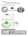
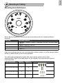
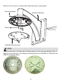
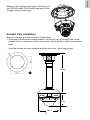
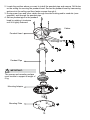
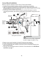
VIVOTEK Fixed Dome Series
Mounting kit
User’s Manual
Using AM-518 mounting adapter
and compatible accessories
Rev. 1.1b
IP Sur veillance
Revison History:
Rev. 1.1: Added Fisheye camera mounting details.
Rev. 1.1a: Updated the model names of compatible accessories.
Rev. 1.1b: Added supported models, FD8335H, FD8135H, and FD8372.
R2.5000
R4.0000
AM-518 Mounting Adapter Mechanical Drawing
AM-518 Mounting Adapter Package Contents
I
Compatible VIVOTEK Cameras
Outdoor series
FD8362, FD8362E, FD8361, FD8335H, FD7141, FD7141V,
FE8171V, FD8372
Indoor series
FD8161, FD8162, FD8135H, FD7131, FD7132
2
English
II
Compatible Accessories
Compatible Accessories (1): AM-311 Pole Mount Bracket
Compatible Accessories (2): AM-411 Corner Mount Bracket
Compatible Accessories (3): AM-711 Junction Box
Compatible Accessories (4): AM-212 Wall Mount Bracket
3
Compatible Accessories (5-1): AM-114 Pendant Head
Compatible Accessories (5-2): AM-115 Pendant Pipe
4
English
III
Mounting & Cabling
Mounting Hole Definitions
Above are the locations of different groups of mounting holes for matching different
cameras:
Hole Type
A
B
C
D
Applicable Cameras
FD8362E, FD8362, FD8361, FD8335H, FD7141, FD7141V, and
FD8372.
FD8161, FD7131, FD7132
FD8162, FD8135H
FE8171V
Align the mounting holes on your mounting plate (outdoor series) or on the camera (indoor
series) to match those on the mounting adapter.
For cabling and configuration details with each camera, please refer to their
documentation. Refer to the table below for the screws to be used with each type of
mounting holes:
Screw Description
Quantity
M5X10 Phillips pan head
4
Applies to
A
M4X20 Phillips pan head
2
B
M4X12 Phillips pan head
3
C
M3X10 Phillips pan head
3
D / D+
5
NOTE:
Due to its unique mechanical design, the mounting procedure for an FE8171V fisheye
camera is specifically described as follows:
1. Remove the camera's top cover.
2. Fasten 2 included screws to the D holes (not the D+ hole).
3. Align the camera with the mounting adapter and let the 2 screws enter the key holes
located on the side where the camera's cabling interfaces reside, e.g., the Ethernet port.
4. Rotate the camera counter-clockwise. You can then see the D+ hole through the slotted
screw hole (in front of the Micro SD slot).
5. Fasten screws to secure the camera with the mounting adapter.
Hole marked as D+
6
English
Wall Mount Installation
Below is a general, sample procedure using a Wall mount bracket:
1. Locate the position where you want to install the wall mount bracket and camera. Drill
holes on the wall for securing the bracket and for routing the cables.
Secure the bracket by hammering anchors into the wall and then fasten screws through
it.
2. Route power lines and other cables through the wall and the bracket.
3. Attach the mounting adapter to the bracket by rotating it clockwise until it is tightly
fastened.
1
4
2
Wall mount
bracket
Cables
3
Mounting adapter
5
Mounting plate
IMPORTANT:
6
The screws and mounting surface must
be able to support a weight of 6 kg.
Dome camera
4. Use the included hex wrench to secure the mounting adapter to the wall mount bracket.
5. For models using the A holes (please refer to the mounting hole diagram on the previous
page), secure its mounting plate to the mounting adapter above.
For the indoor models, mounting plates are not necessary.
6. For outdoor models - secure the camera to the mounting plate.
For indoor models -secure the camera directly to the mounting adapter.
When cabling is done, proceed with initial setup such as enabling network access, focus
tuning, or zooming. When done, secure the outer dome cover.
7
Below is a closer view on routing cables and matching a mounting plate.
Mounting Adapter
Wall Mount Bracket
Cables
FD8362E Mounting Plate
NOTE:
Use the correct type of screws when installing cameras to the mounting adapter. Refer to
page 5 for the screw type. The sample mounting positions for FD8362E (or FD8335H and
FD8372) are shown below.
A
A
A
A
8
English
Shown on the right is an exemplary illustration for
the FD8135H and FD1862 indoor cameras. Refer
to page 5 for the screw type.
Pendant Pipe Installation
Below is a sample procedure using a Pendant pipe:
1. Determine a hard surface ceiling location, and use the four mounting holes on the
pendant head to mark the positions where holes will be drilled to secure the pendant
head.
Note that screws are user-supplied and they should be 11mm long at least.
307 mm
1
115 mm
9
178 mm
2. Locate the position where you want to install the pendant pipe and camera. Drill holes
on the ceiling for securing the pendant head. Secure the pendant head by hammering
anchors into the ceiling and then fasten screws through it.
3. Route power lines and other cables through the side bushing and/or conduits (usersupplied), and through the pendant pipe.
4. Secure pendant pipe to the pendant
head by rotating it clockwise
until it is tightly fastened.
Cables
3
Pendant Head
2
5
4
Pendant Pipe
7
IMPORTANT:
The screws and mounting surface
must be able to support a weight of
6 kg.
Mounting Adapter
6
Mounting Plate
8
10
When cabling is done, proceed with initial setup such as enabling network access, focus
tuning, or zooming. When done, secure the outer dome cover.
11
English
5. Secure the connection using the included hex wrench.
6. Attach mounting adapter to the pendant pipe by rotating it clockwise until it is tightly
fastened.
7. Secure the connection using the included hex wrench.
8. For models using the A holes (please refer to the mounting hole diagram on page 8),
secure its mounting plate to the mounting adapter above.
• For the indoor models, mounting plates are not necessary.
• For outdoor models - secure the camera to the mounting plate.
• For indoor models -secure the camera directly to the mounting adapter.
Corner Mount Installation
Below is a general, sample procedure using a Corner mount bracket:
1. Combine the two brackets together using the included nuts and washers.
2. Align the assembled brackets with the desired position. Align screw holes on the
brackets against the wall. Drill holes on the wall for securing the bracket and for routing
the cables. Hammer anchors into the wall.
3. Route power lines and other cables through the included cable gland, conduits
(separately purchased), and install the cable gland to the brackets' through hole in the
center.
Wall mount
bracket
5
1
Corner Mount
Bracket
Mounting
adapter
Dome
camera
2
6
3
4
Cable gland and conduits
IMPORTANT:
The screws and mounting surface must
be able to support a weight of 6 kg.
4. Secure corner mount brackets to the wall. Screws are user-supplied.
5. Fill the unused holes on the bracket with the included silicone stoppers.
6. Use the included hex bolts, washers, and nuts to secure a wall mount bracket to the
corner mount bracket.
7. The rest of the mounting procedure is identical to those described in the Wall Mount
installation on page 7.
12
English
Pole Mount Installation
Below is a general, sample procedure using a Pole mount bracket:
1. Route power lines and other cables through the included cable gland, pass them
through conduits (separately purchased), and install the cable gland to the pole mount
bracket.
2. Locate the position where you want to install the pole mount bracket and camera.
Unwrap the stainless belts, feed them through the openings on the sides of the bracket,
and then strap them around the pole. Use a pincer and flathead screwdriver to fasten
the bracket to the pole.
3. Fill the unused screw holes using the included silicone stoppers.
4
Pole mount
bracket
Wall mount
bracket
2
Mounting
adapter
Mounting
plate
3
Dome
camera
1
Cable gland and conduits
4. Secure wall mount bracket using the included hex bolts, washers, and nuts.
The rest of the mounting procedure is identical to those described in the Wall Mount
installation on page 7.
13


![Cover [FD7131] Outline](http://vs1.manualzilla.com/store/data/006153350_1-7c92864b367e6483a8a42a379e46e580-150x150.png)

![Cover [FD7132]-outline.ai](http://vs1.manualzilla.com/store/data/006040135_1-f75a148c91b11b3c3e29997e0c59b0c6-150x150.png)