1
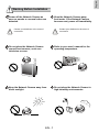
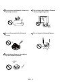
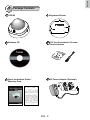
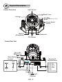
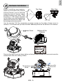
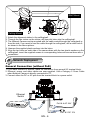
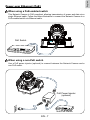
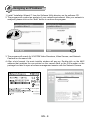
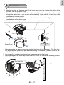
FD8162
2 MP • PIR • Focus Assist
P/N:625014500G Ver.1.0
Copyright c 2011 VIVOTEK INC. All rights reserved.
English
Warning Before Installation
Power off the Network Camera as
soon as smoke or unusual odors are
detected.
Contact your distributor in the event of
occurrence.
Keep the Network Camera away
from water. If the Network Camera
becomes wet, power off immediately.
Contact your distributor in the event of
occurrence.
Do not place the Network Camera
around heat sources, such as a
television or oven.
Refer to your user's manual for the
operating temperature.
Keep the Network Camera away from
direct sunlight.
Do not place the Network Camera in
high humidity environments.
EN - 1
Do not place the Network Camera on
unsteady surfaces.
Do not touch the Network Camera
during a lightning storm.
Do not disassemble the Network
Camera.
Do not drop the Network Camera.
Do not insert sharp or tiny objects
into the Network Camera.
EN - 2
English
1
Package Contents
FD8162
Alignment Sticker
Software CD
T10 Torx Screwdriver/ Screws /
Plastic Anchors
Quick Installation Guide /
Warranty Card
DC Power Adapter (Optional)
EN - 3
2
Physical Description
Light Sensor
Camera Front View
Black Cover
Lens
IR LEDs
(18 units, effective up to 15m)
Focus Assist
Button
Built-in
Microphone
Reserved
PIR Sensor
Camera Rear View
Micro SD/
SDHC Card
Slot
Reset Button
Jumpers
Microphone Video Output
NTSC
internal
60Hz
external
PAL
50Hz
1
2
Reset
Int.
Micro SD Card
1 2 3 4 5 678
General IO
Terminal Block
NTSC
AV Out
Ext.
Ethernet
PAL
Audio In
Audio/Video Out
Audio In
10/100BaseT
Ethernet
EN - 4
1. DC 12V2. DC 12V+
3. AC 24V_2
4. AC 24V_1
5. DI- (GND)
6. DI+
7. DO8. DO+ (+12V)
English
3
Hardware Installation
Before installing your camera,
make sure the built-in PIR (Passive
Infrared Sensor) can be directed
toward the area of interest, where
possible intrusion may occur. (The
sensitivity of PIR sensor depends
on the object size and temperature
differences between the object and
the background environment.)
Side View
Top View
50
5m
41
50
5m
41
Use the included T10 Torx screwdriver to loosen screws on the sides of dome cover to
remove it. You should then jot down the MAC address printed on the bottom of the camera.
Dome Cover
Bottom of the
Camera
Remove the black cover as shown below so that you can fine-tune the focus and zoom the
camera later when the cabling is done.
Tilt Ajustment
Screw
EN - 5
Focus Ctrl
Zoom Ctrl
Wall Mount
Ceiling Mount
1. Attach the alignment sticker to the ceilling/wall.
2. Through the two circles on the sticker, drill two pilot holes into the ceilling/wall.
3. The Network Camera can be mounted with the cable routed through the ceiling/wall or
from the side. If you want to feed the cable through the ceiling/wall, drill a cable hole A
as shown in the above picture.
4. Hammer the supplied plastic anchors into the holes.
5. Align the two holes on each side of the camera base with the two plastic anchors on the
ceilling/wall, insert the supplied screws to corresponding holes and secure them with a
screwdriver.
4
Network Deployment
General Connection (without PoE)
1. If you have external DI devices, make the connection from general I/O terminal block.
2. Ethernet, power, and other cables are user-supplied. Use a Category 5 Cross Cable
when Network Camera is directly connected to PC.
3. Connect either the DC or AC pins from the terminal block to a power outlet.
Ethernet
Switch
POWER
COLLISION
1
2
3
4
5
Pin3 & 4 AC 24V
LINK
RECEIVE
PARTITION
Red
Black
EN - 6
Pin1 & 2 DC 12V
English
Power over Ethernet (PoE)
When using a PoE-enabled switch
This Network Camera is PoE-compliant, allowing transmission of power and data via a
single Ethernet cable. Follow the below illustration to connect the Network Camera to a
PoE-enabled switch via Ethernet cable.
PoE Switch
POWER
COLLISION
1
2
3
4
5
LINK
RECEIVE
PARTITION
When using a non-PoE switch
Use a PoE power injector (optional) to connect between the Network Camera and a
non-PoE switch.
PoE Power Injector
(optional)
POWER
COLLISION
1
2
3
4
5
LINK
RECEIVE
PARTITION
Non-PoE Switch
EN - 7
5
Assigning an IP Address
1. Install “Installation Wizard 2” from the Software Utility directory on the software CD.
2. The program will conduct an analysis of your network environment. After your network is
analyzed, please click on the “Next” button to continue the program.
Installation
Wizard 2
3. The program will search for VIVOTEK Video Receivers, Video Servers, and Network
Cameras on the same LAN.
4. After a brief search, the main installer window will pop up. Double-click on the MAC
address that matches the one printed on the camera label or the S/N number on the
package box label to open a browser management session with the Network Camera.
00-02-D1-07-25-8A
0002D107258A
192.168.5.151
0002D107258A
EN - 8
FD8162
English
6
Ready to Use
1. A browser session with the Network Camera should prompt as shown below.
2. You should be able to see live video from your camera. You may also install the 32channel recording software from the software CD in a deployment consisting of multiple
cameras. For its installation details, please refer to its related documents.
For further setup, please refer to the user's manual on the software CD.
EN - 9
7
Adjusting the Lens
Based on the live image retrieved from the camera, adjust the camera lens to the desired
view angle:
1. Turn the lens module left and right.
2. Loosen the tilt adjustment screws on both sides of the camera and then turn the lens
module up and down. Upon completion, tighten the screws.
3. Turn the lens to adjust the image orientation.
2
3
Tilt 65°
1
Pan 350°
3-axis Mechanism Design
Rotate 350°
The sophisticated 3-axis mechanism design offers very flexible, easy hardware installation
for either ceiling or wall mount.
To adjust the zoom factor and focus range
1. Loosen the zoom controller and then adjust zoom factor by moving the controller left and
right. Upon completion, tighten the zoom controller screw.
2. Loosen the focus controller and then adjust focus range by moving the controller left and
right. Upon completion, tighten the focus controller screw.
W
N
T
8
DO NOT over-tighten the controller
bars. Doing so will damage the
camera lens module.
EN - 10
English
8
Completion
1. Align the notches on the inner side of the black cover with the rivets on the sides of the
lens, and then fix the black cover.
2. If you choose to feed the cable through the ceiling/wall, arrange the cables neatly
through the cable hole A (not shown in the drawing). If you choose to feed the cable
from the side, remove plate B.
3. Attach the dome cover to the camera as the direction shown below. Tighten two screws
from the sides of the dome cover.
4. Finally, make sure all parts of the camera are securely installed.
1
A
Black Cover
3
B
2
Be aware of the
cable route!
Dome Cover
1. When mounting the camera, you can use the key hole slot at the bottom. The key hole
slot helps facilitate installation and a safe mounting. First fasten a pioneer screw to the
wall/ceiling. Mount the camera to the screw.
2. Use a pencil to mark the locations of the 3 permanent mounting holes.
3. When cabling and the initial adjustment is done, mount the camera by fastening screws
to the 3 mounting holes.
Key Hole Slot
Pioneer Screw
Mounting Holes
EN - 11