1
ASSEMBLY
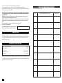
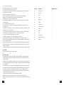
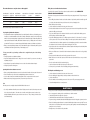
DETAILED PART DRAWING
• Before throwing the packaging material out, make sure no part is left inside. If so, take it out and install it.
Use the part listing for check-up and the installation drawing for guidance.
• To seal threading couplings use teflon tape.
• Your machine is delivered pre-assembled.
• Assemble your machine in accordance with drawings or pictures included in the manual.
• Couplings blasting unit/hose and hose/blasting pistol must be secured with safety clips. Using your
machine without the coupling safety clips is prohibited. You may damage the machine or injure yourself.
When you finished assembling your machine, perform leakage test and inspection according
to the following steps:
Inspection of reservoir couplings for leakage.
• Close the valve 14 - the control lever must be
perpendicular to the valve body.
• Close both valves 18 under the pressure gauge.
Also close the sandblasting substance feed in
the lower part of the reservoir. The control lever
must be perpendicular to the valve body.
• Connect the compressed air supply hose to the
inlet 15 and secure it in place with the safety clip
(not included).
• Place seal on the lid of the basting substance
reservoir.
• Using one of your hands, close the opening of
the blasting substance reservoir with the lid 1.
Pull the lid slightly upwards to make sure that it
is closed tightly.
• With your other hand, slowly open the valve 14.
• Observe the rising pressure inside the reservoir
on the pressure gauge 5.
• Close the valve 14.
• Observe the pressure decrease on the gauge.
The pressure gauge must show the same value
constantly.
• If you suspect a leakage, use water with soup or
your ears to detect the location of the leak. Once
you located the leak, mark it down.
• Let the air our of the system as follow.
• Slowly open the valve 18 under the pressure gauge 5.
• Slowly press the trigger of the blasting pistol to let the air pressure out of the reservoir.
6
11