1
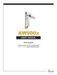
AW900x
User’s Manual
Thank you for your purchase of the AW900x Wireless
Ethernet Bridge.
If you have any questions when configuring your
AvaLAN Bridge, please send us an email:
[email protected]
For advanced installation information see
www.avalanwirelss.com
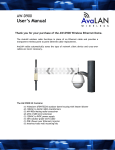
The AW900x Kit Contains:
(2)
(2)
(2)
(2)
AW900x Radio Units
80-240VAC to 9VDC Power Adapters
Power over Ethernet Injectors
30 ft CAT5e Outdoor Cables
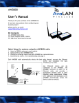
Quick Setup:
1. Plug in the AW900x using the supplied injector and power supply.
2. Connect an Ethernet cable from each AW900x to a network device.
3. Send Ethernet traffic. For troubleshooting see page 2.
Each AW900x radio automatically selects the best radio channel, encrypts the Ethernet
traffic and transports the data wirelessly to its mate.
900 MHz Digital
Ethernet Bridge
RF Connector
RP-TNC
AW900x
Power over
Ethernet
Injector
Data
Ethernet
RJ45/10BT
Power
110VAC
Power and Data
Power
300ft max CAT5e
Outdoor grade cable
9-48VDC
P5/2.1 plug
RF Connector
RP-TNC
AW900x
Power over
Ethernet
Injector
Data
Ethernet
RJ45/10BT
Power
110VAC
Power and Data
Power
300ft max CAT5e
Outdoor grade cable
9-48VDC
P5/2.1 plug
Any Ethernet device can be connected to the AW900x. The AW900x functions in place
of an Ethernet cable and provides a transparent wireless point to point Ethernet cable
replacement. Cross-over cables are not necessary as the AW900x automatically
senses the device (client or switch).
LED display:
The AW900x has a 16 LED display to display the status of the device.
Name
Power
RF Link
RF TX
RF RX
Eth Link
Activity
1 (channel)
2 (channel)
4 (channel)
8 (channel)
Link Quality
Meter
The more LEDs that
are lit the higher the
link quality.
Function
Unit has power and has successfully booted.
The radio has successfully synchronized with it
partner.
Radio transmission is occurring.
Radio reception is occurring.
The Ethernet Port has a valid Ethernet connection
The AW900m is processing data
By adding the numbers that are lit the user can
determine the current radio channel.
Color
Red
Green
Excellent link quality –
No retransmissions
Very good link quality –
Few retransmissions
Good link quality –
Occasional retransmissions
Fair link quality –
Some retransmissions
Poor link quality –
Many retransmissions
No link quality
No link available
Green
1 903.12500 MHz
2 905.20833 MHz
3 907.29167 MHz
4 909.37500 MHz
5 911.45833 MHz
6 913.54167 MHz
Green
Green
Green
Green
Green
7 915.62500 MHz
8 917.70833 MHz
9 919.79167 MHz
10 921.87500 MHz
11 923.95833 MHz
12 926.04167 MHz
Green
Amber
Amber
Red
Red
Troubleshooting:
See the online installation tutorial and FAQ at www.avalanwireless.com
No Power LED:
Check the power connections.
No Radio Link LED:
The radio is looking for its matched partner. If both units are powered up and the
Power LEDs are active they may be too far away to create the radio connection. Try
other locations that may have a less obstructed path or try to reorient the antennas.
Yagi type antennas get their best range when they are oriented to point directly at
each other with the antenna elements oriented in the same plane (eg. vertically or
horizontally)
Radio LINK LED on but Link Quality Indicator is low:
The units may be too far away to create a good radio connection. Try other locations
that may have a less obstructed path or try to reorient the antennas.
No Ethernet LINK LED:
Check your network connections.
Installing Multiple systems in close proximity:
See the online installation tutorial and FAQ at www.avalanwireless.com
Still not working?
Temporarily use an Ethernet cable to see if the network is working over a wired
connection. If an Ethernet cable does not work then the problem is with the network.
Support Email: [email protected]
Support helpline: (650) 384-0000
Advanced Settings:
Automatic frequency selection mode (DIP switches – all OFF for automatic mode)
The AW900x is designed to automatically select and continuously optimize the
performance of its radio channel. The radio channel is monitored to ensure it is
providing low error rates necessary for successful radio transmission. In the event that
the error rate rises, the AW900x will autonomously change to a new channel. There
are 12 non-overlapping channels.
Manual frequency selection mode
To restrict the operation of the AW900x to a subset of the 902-928 band, the user may
activate a manual selection mode that allows the radio to automatically choose the
best channel within a grouped subset of the 12 available channels. This is enabled by
the 8 position DIP switch on the master unit. These settings allow the AW900x to
operate on the optimal channel in one of three subsets, LOW 4, MID 4 or HIGH 4. The
DIP switch setting are:
Channels
LOW 4 - 1,2,3 or 4
MID 4 - 5,6,7 or 8
HIGH 4 - 9,10,11 or 12
DIP Setting
2 On / 3 Off
2 Off / 3 On
2 On / 3 On
Frequency
902-910 MHz
910-918 MHz
918-927 MHz
Or - the user may wish to select a specific channel. This can be done by setting DIP
switches 5-8 as shown in the table below. [Turn DIP 2 Off / 3 Off]
Channel
1
2
3
4
5
6
7
8
9
10
11
12
DIP Setting
5 On / 6 Off / 7 Off / 8 Off
5 Off / 6 On / 7 Off / 8 Off
5 On / 6 On / 7 Off / 8 Off
5 Off / 6 Off / 7 On / 8 Off
5 On / 6 Off / 7 On / 8 Off
5 Off / 6 On / 7 On / 8 Off
5 On / 6 On / 7 On / 8 Off
5 Off / 6 Off / 7 Off / 8 On
5 On / 6 Off / 7 Off / 8 On
5 Off / 6 On / 7 Off / 8 On
5 On / 6 On / 7 Off / 8 On
5 Off / 6 Off / 7 On / 8 On
Center Frequency
903.12500 MHz
905.20833 MHz
907.29167 MHz
909.37500 MHz
911.45833 MHz
913.54167 MHz
915.62500 MHz
917.70833 MHz
919.79167 MHz
921.87500 MHz
923.95833 MHz
926.04167 MHz
Site survey mode (DIP switch 4 - default is OFF for normal operation)
In this mode the AW900x can perform a site survey. With this mode activated the
radios send and receive at 100% capacity by transceiving self-generated simulated
data. The installer can monitor the Link Quality display to assess channel quality while
optimizing antennae orientation. The installer can manually select each channel to
evaluate performance and identify the best channels for operation. By identifying
channels with poor performance it is possible to identify possible interferers and use
“manual frequency selection mode” to avoid portions of the band or select a fixed
operating frequency. Note: Ethernet traffic does not get transported while the radios
are in this mode.
Power save mode (DIP switch 1 - default is OFF for normal LED display)
In this mode the display LEDs can be turned off for low power applications (solar).
Technical Specifications: (typical)
Characteristic
RF transmission rate:
Throughput:
Output power:
Receive sensitivity:
Latency:
Jitter:
Voltage Range:
Power Consumption:
Radio channels:
Automatic frequency select:
Manual frequency mode:
Status LEDs:
Error correction technique:
Adjacent-band rejection:
Temperature range
Power over Ethernet:
Specification - description
1.5 Mb/s
935 Kb/s
+21dBm – (4 Watts EIRP with 15dBi antennae)
-97dBm at 10e-4 BER (-112dBm with 15dBi antennae)
< 2ms – assuming a dedicated wireless link to client device.
±0.5ms – depending upon packet size, interference and SNR.
6-48VDC
TX <1.5Watts RX <0.6Watts over 6-48VDC input voltage.
12 Non-overlapping
Yes – radio channel automatically selected and adaptively optimized
Yes
Power, RF Link, Ethernet Link, Traffic, RF RX, RF TX, 4/Channel and
6/Link Quality
Sub-block error detection and retransmission
SAW receiver filter attenuates cellular and pager interference.
-40°C to 70°C
Use with 6VDC to 48VDC POE systems with lines 4/5 positive, 7/8 ground.
Product limited warranty:
This product is warranted to the original purchaser for normal use for a period of 180 days from the date
of purchase. If a defect covered under this warranty occurs Avalan will repair or replace the defective
part, at its option, at no cost. This warranty does not cover defects resulting from misuse or modification
of the product.
Compliance Statement ( Part 15.19 )
This device complies with Part 15 of the FCC Rules.
Operation is subject to the following two conditions:
1. This device may not cause harmful interference, and
2. This device must accept any interference received, including interference that may cause undesired operation.
Warning ( Part 15.21 )
Changes or modifications not expressly approved by the party responsible for compliance could void the user’s authority to operate
the equipment.
RF Exposure ( OET Bulletin 65 )
To comply with FCC RF exposure requirements for mobile transmitting devices, this transmitter should only be used or installed at
locations where there is at least 20cm separation distance between the antenna and all persons.
Information to the User - Part 15.105 (b)
Note: This equipment has been tested and found to comply with the limits for a Class B digital device, pursuant to part 15 of the
FCC Rules. These limits are designed to provide reasonable protection against harmful interference in a residential installation. This
equipment generates, uses and can radiate radio frequency energy and, if not installed and used in accordance with the instructions,
may cause harmful interference to radio communications. However, there is no guarantee that interference will not occur in a
particular installation. If this equipment does cause harmful interference to radio or television reception, which can be determined by
turning the equipment off and on, the user is encouraged to try to correct the interference by one or more of the following measures:
--Reorient or relocate the receiving antenna.
--Increase the separation between the equipment and receiver.
--Connect the equipment into an outlet on a circuit different from that to which the receiver is connected.
--Consult the dealer or an experienced radio/TV technician for help.
V5 August 9, 2006