1
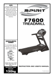
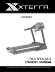
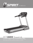
OWNER’S MANUAL
PLEASE CAREFULLY READ THIS ENTIRE MANUAL BEFORE
OPERATING YOUR NEW TREADMILL!
Table of Contents
Safety hints…………………………………………………………………………2
Introduction………………………………………………………... ………………3
Specifications……………………………………………………………………….3
Assembly Pack Check List List……………………………………………………4
Assembly Instructions………………………………………………………………6
Folding Instructions…………………………………………………………………10
Transport Instructions………………………………………………………………10
Operation of Your Treadmill…………………………………………………..……11
Programmable Features……………………………………………………………15
General Maintenance…………………………………………………………..…...22
Service Checklist-Diagnosis Guide…………………………………………..……25
Exploded View Diagram…………………………………………... ……………….27
Parts List….………………………………..……………………..…………………..28
ST90-YT007_1208(SL)A
-1-
Safety hints
IMPORTANT: THIS UNIT IS INTENDED FOR HOUSEHOLD USE ONLY
SAFETY PRECAUTIONS
Thank you for purchasing our product. Even though we go to great efforts to ensure the quality of each product,
occasional errors and/or omissions do occur. In any event should you find this product to be defective or
missing a part please contact our Customer Service Department.
Your treadmill was designed and built for optimum safety. However, certain precautions apply
whenever you use your treadmill. Be sure to read the manual before assembly and operation.
Also, please note the following safety precautions:
DANGER: To reduce the risk of electric shock, always unplug the treadmill from the electrical outlet
immediately after using and before cleaning.
1.
2.
3.
4.
5.
6.
7.
8.
9.
10.
11.
12.
13.
14.
Read OWNER OPERATING MANUAL and all accompanying literature and follow it carefully before using
your treadmill.
If dizziness, nausea, chest pains, or any other abnormal symptoms are experienced while using this
equipment, STOP the workout at once. CONSULT A PHYSICIAN IMMEDIATELY.
Never leave the treadmill unattended when plugged in. Unplug from the outlet when not in use and before
removing or replacing parts.
Never operate the treadmill if it has a damaged cord or plug, if it is not working properly, if it has been
dropped, damaged, or exposed to water.
Do not pull the treadmill by the power supply cord or use cord as a handle. Keep cord away from heated
surfaces and open flames.
Fitness equipment must always be installed and used on a flat surface. Do not use outdoors or near water.
Do not insert any objects into any openings.
Keep children and pets away from this equipment at all times while exercising.
Handicapped individuals should have medical approval and close supervision when using this treadmill.
Do not place hands or feet under the treadmill. Always keep hands and legs off of the treadmill when others
are using it.
Never turn on treadmill while standing on treadbelt. Always return the treadmill to slow speed to provide for
safe dismount and low speed restart.
a-To disconnect, turn all controls to the off position, then remove plug from outlet.
b-Use the treadmill only for it is intended use as described in this manual.
c-Warm up 5 to 10 minutes before each workout and cool down 5 to 10 minutes afterward. This allows
your heart rate to gradually increase and decrease and will help prevent straining muscles.
d-Never hold your breath while exercising. Breathing should remain at a normal rate in conjunction with
the level of exercise being performed.
e-Start your program slowly and very gradually increase your speed and distance.
f-Always wear suitable clothing and footwear while exercising. Do not wear loose fitting clothing that
could become entangled with the moving parts of your treadmill.
g-Do not walk or jog barefoot, in stocking feet or loose fitting shoes or slippers.
h-Care must be taken when lifting or moving the equipment, so as not to injure your back. Always use
proper lifting techniques.
If the supply cord is damaged, it must be replaced by the manufacturer, its service agent or similarly
qualified persons in order to avoid a hazard.
The appliance is not to be used by children or persons with reduced physical, sensory or mental capabilities,
or lack of experience and knowledge, unless they have been given supervision or instruction
Children being supervised not to play with the appliance
WARNING: Before beginning any exercise program consult your physician. This is especially important for
individuals over the age of 35 or persons with pre-existing health problems. Read all instructions before using
any fitness equipment. We assume no responsibility from personal injury or property damage sustained by or
through the use of this product.
CAUTION!! Please be careful when opening this unit.
-2-
Introduction
The treadmill has been designed and constructed to provide trouble free usage and enjoyable exercise.
You can greatly improve your understanding and benefits of exercising by carefully reading the instructions
given in this manual. Please familiarize yourself with the maintenance advice provided for you.
Specifications
•
•
•
•
•
Drive Motor: 2.75 hp
Speed Range: 1 – 16 kmph / 0.5 – 10 mph
Running Surface: 510 m/m x 1525 m/m
Incline Level: 0-15 Levels
Folding Design: YES
Fan
Console
Safety
Ke
Handgrip Tube
Upright
Running Belt
Main
MAX.USER WEIGHT 150 KGS
Fr
Wheel
-3-
Assembly Pack Check List
#97. 5/16" × 1/2"
Hex Head Bolt (8pcs)
#76. Ø5/16" × Ø18 × 1.5T
Flat Washer (8 pcs)
#95. M5 × 15m/m
Phillips Head Screw (6 pcs)
#93. Ø10
Split Washer (4 pcs)
#94. 3/8" × 1-1/2"
Button Head Socket Bolt (4pcs)
#96. 5/16" × 3/4"
Button Head Socket Bolt (4pcs)
#54. 800m/m
Trapezoidal Safety Key (1pc)
#101.Lubricant
(1pc)
-4-
#98. Combination M5(25 × 90m/m)
Allen Wrench & Phillips Head Screw
Driver (1pc)
#99. M6(68 × 88)
Allen Wrench (1pc)
#100. 13m/m
Wrench (1pc)
-5-
Assembly Instructions
Step 1.
Remove the unit from the box and put it on a flat and level floor.
Step 2.
Connect Computer Cable (Upper/Lower) (44) with Computer Cable (Middle) (43) then insert Right and
Left Uprights (4) and (5) into the Frame Base (2) and use 13m/m Wrench (100) to tighten 8 pcs of 5/16"
×1/2" Hex Head Bolts (97) and 8pcs of Ø5/16" × Ø18 × 1.5T Flat Washer (76).
4
76
97 97
100
97
44 76
76
97
5
43
76
97
76
97
76
76
97
2
-6-
97
76
Step3.
Install Frame Base Cover (L) and (R),(33) and (34), on the Frame Base (2) and secure with 6 pcs of
M5 × 15m/m Phillips Head Screws (95) by using Combination M5 Allen Wrench & Phillips Head Screw
Drive (98).
34
95
95
95
98
Step4.
Connect Computer Cable (Upper/Lower) (44) with Computer Cable (Middle) (43).
-7-
Step5.
Insert Console Assembly (19) into right and left Uprights (4) and (5) and secure with 4 pcs of 3/8" ×
1-1/2" Button Head Socket Bolts (94) with 4 pcs of Ø10 Split Washers (93) by using M6(68 × 88)Allen
Wrench (99).
Step 6.
Install Handrail Support (9) between right and left Uprights (4) and (5) and use Combination M5 Allen
Wrench & Phillips Head Screw Driver (98) to tighten 4 pcs of 5/16” x3/4” Button Head Socket Bolts
(96).
98
96
96
9
5
96
4
-8-
Step7.
Put left and right Drink Bottle Holders (19-3) and (19-4) in their places on the Console Assembly (19).
19-3
19-4
19
NOTE: Please Tighten All Screws After All Components Assembly
Complete.
-9-
Folding instructions
Do not attempt to move the unit unless it is in the folded and locked position. Be sure the power
cord is secured to avoid possible damage. Use both handrails to maneuver the unit to the
desired position.
TO FOLD THE TREADMILL
Lift the deck until the latch clicks in place.
TO UNFOLD THE TREADMILL
Press the tube with your foot at the yellow sticker
To release latch.See picture to the right.
Transportation instructions
The treadmill is equipped with four transport wheels that are engaged when the treadmill is
folded. After folding simply roll the treadmill away.
-10-
Operation of Your Treadmill
Getting familiar with the control panel
■Console
GETTING STARTED CONSOLE :
Power the treadmill on by plugging it into an appropriate wall outlet, then turn on the power switch located
at the front of the treadmill below the motor hood. Ensure that the Safety Key is installed, as the treadmill
will not power on without it.
When the power is turned on, a message will scroll across the Message Window showing the current
software version. Then the Time and Distance Windows will display Odometer readings for a short time,
Time Window will show how many hours the treadmill has been in use and the Distance Window will show
how many miles (or Kilometers if the treadmill is set to metric readings) the treadmill has gone. The
treadmill will then enter idle mode, which is the starting point for operation.
-11-
QUICK-START OPERATION
1. Attach the Safety Key to wake the display up (if not already on).
2. Press the Start key to begin belt movement then adjust to the desired speed using the Speed /
keys on the console. You may also use the Quick speed keys 1, 2, 4, 6, 8, or 10 to adjust the speed.
3. To slow thetread-belt press and hold the Speed key on the console to the desired speed. You may
also press the Quick speed adjust keys, 1 through 10.
4. To stop the tread-belt press Stop key or pull away Safety Key.
PAUSE/STOP/RESET FEATURE
1. When the treadmill is running the pause feature may be utilized by pressing the red Stop key once.
This will slowly decelerate the tread-belt to a stop. The incline will go to zero percent. The Time,
Distance and Calorie readings will hold while the unit is in the pause mode. After 5 minutes the
display will reset and return to the start up screen.
2. To resume your exercise, when in Pause mode, press the Start key. The speed and incline will return
to their previous settings.
Pause is executed when the Stop button is pressed once. If the Stop button is pressed a second
time, the program will end and a workout summary will be displayed. If the Stop button is pressed
a third time, the console will return to the idle mode (start up) screen. If the Stop button is held
down for more than 3 seconds the console will reset.
■
INCLINE FEATURE
1. Incline may be adjusted anytime after belt movement.
2. Press and hold the Incline / keys on the console to achieve desired level of incline. You may also
choose a more rapid increase / decrease by selecting desired key, 2, 4, 6, 8, 10, or 12 on the left hand
side of console.
3. The incline window display will indicate incline position as adjustments are made.
-12-
DOT MATRIX CENTER DISPLAY
Twenty columns of dots (8 high) indicate each segment of a workout.
The dots are only to show an approximate level
(speed/incline) of effort. They do not necessarily indicate a specific
value - only an approximate percent to compare levels of intensity. In
operation, the speed/incline dot matrix window will build a profile
“picture” as values are changed during a workout. When the word
“Speed” is lit above the dot matrix it indicates that the Speed profile is
being displayed and when the word “Incline” is lit above the dot matrix
it indicates the Incline profile is being displayed.
You may change the Dot Matrix profile view between Speed and Incline by pressing the Enter button. After
pressing Enter to view the two profiles, pressing it a third time will automatically alternate the Speed and
Incline displays, showing each one for five seconds.
1/4 MILE TRACK
The 1/4 mile track is displayed around the dot matrix window. The flashing dot indicates your progress. The
number of laps you complete are accumulated in the lap counter, which is below the Message Window.
MESSAGE WINDOW DISPLAY
The Message Window will initially display Program Name. Each time the Display button is pressed the
next set of information will appear. The order of information displayed will be: Pace, Incline, Laps, Verticle,
Segment Time, Max Speed (in mph), and Data Scan mode. In Data Scan mode, the displayed
information will change every 4 seconds in the Message Window.
CALORIE DISPLAY
Displays the cumulative calories burned at any given time during your workout.
Note: This is only a rough guide used for comparison of different exercise sessions, which cannot be used
for medical purposes.
There is an Audio Input Jack ( ) on the front of the console and built-in speakers. You may plug any
low-level audio source signal into this port. Audio sources include MP3, Ipod, portable radio, CD player or
even a TV or computer audio signal. There is an audio patch cable included and also a headphone jack
( ) for private listening.
-13-
PULSE FEATURE
The Pulse (Heart Rate) Window will display your current heart rate in beats per minute during the workout.
You must use both stainless steel sensors on the front cross bar to display your pulse or wear the wireless
chest strap. The pulse value will display anytime the upper display is receiving a pulse signal.
TURNING OFF TREADMILL
1.
2.
The display will automatically turn off – go to sleep – after 30 minutes of inactivity when in the Pause /
Stop mode.Almost all power for the treadmill will be off except for some circuits that are needed to
detect if any key is pressed, indicating the console should “wake up”. When the console is “asleep” the
treadmill draws very little power, about as much as your television when it is turned off.
Removing the safety key is similar to entering “sleep” mode. Turning off the main power switch in the
front of the treadmill will completely remove any power.
**ATTENTION**
Your new console comes configured in an in-store ‘Display Mode’ of operation, where the console will
remain powered on unless the main power switch is turned off. To exit the display mode, for normal
operation, press and hold the Stop, Enter and Display keys for 5 seconds; the display will show: Display
mode - On. Use any of the Program, Incline or Speed / keys to change the setting to Off then press
Enter.
-14-
PROGRAMMABLE FEATURES
The F60 has ten built-in programs: one Manual program, five preset profiles, two user defined programs
(U1 & U2) and two Heart Rate programs (HR1 & HR2).
Hill
The Hill program simulates going up and down a hill. The workload will steadily increase and then
decrease during the program.
Fat Burn
The Fat Burn program is designed, as the name implies, to maximize the burning of fat. There are many
schools of thought on the best way to burn fat but most experts agree that a lower exertion level that stays
at a steady work- load is the best. The absolute best way to burn fat is to keep your heart rate at around
60% to 70% of its maximum potential. This program does not use heart rate but simulates a lower, steady
exertion workout.
Cardio
The Cardio program is designed to increase your cardiovascular function and endurance. This is exercise
for your heart and lungs. It will build up your heart muscle and increase blood flow and lung capacity. This
is achieved by incorporating a higher level of exertion with slight fluctuations in work.
Strength
The Strength program is designed to increase muscular strength in your lower body. This program will
steadily increase in workload to a high level and forces you to sustain it. This is designed to strengthen and
tone your legs and glutes (muscles of the butt).
Interval
The Interval program takes you through high levels of intensity followed by periods of low intensity. This
program increases your endurance by depleting your oxygen level followed by periods of recovery to
replenish oxygen. Your cardiovascular system gets programmed to use oxygen more efficiently this way.
This program also forces your body to become more efficient due to spikes in heart rate, between recovery
periods. This aids in heart rate recovery from intense activities.
-15-
SELECTING A PROGRAM
1. Press the Speed / keys to view the programs on the screen then press the Enter key to select the
program you would like to perform. The display will prompt you through the programming steps or you
can just press the Start key to begin the program using the preset program values for age, weight and
other program specific information.
2.
3.
4.
5.
6.
If Enter was pressed, the Message Window will display Age. You may use any of the /
keys to adjust your age. After adjusting press the Enter key.
Note: You may press Start at any time during the programming to start the program with the
information you’ve already input.
The Message Window will now be displaying a value, which is your body weight. Entering the correct
body weight will affect the calorie count. Use any of the / keys to adjust, then press Enter.
■ Calorie Display Note: No exercise machine can give you an exact calorie count because there
are too many factors which determine exact calorie burn for a particular person. Even if
someone is the exact same body weight, age and height, their calorie burn may be very differ- ent
than yours. The Calorie display is to be used as a reference only to monitor improvement from
workout to workout.
The Time Window and Message Window will now be displaying a value, which is total workout time
desired. Use any of the / keys to adjust, and then press Enter. After adjusting, press the Enter
key.
The Message Window will display the preset max speed of the selected program. Use any of the
/ keys to adjust, and then press Enter. Each program has various speed changes throughout;
this allows you to limit the highest speed the program will reach at it’s peak.
Press Start to begin the program. The program will begin with a 3 minute warm-up. If you want to
bypass this and go directly to the beginning of the program, press Start again.
-16-
USER PROGRAMS
1.
2.
3.
4.
5.
6.
Select User 1 or User 2 via the Speed / keys then press
Enter. Note that the dot matrix display portion will have a single
row of dots at the bottom (Unless there is a previously stored
program). If there is a program stored under the button that is
pressed, it will be retrieved. If not, you have the option of
programming in your first name. The Message Window will
display and flash the letter “A” . To change it, press the any key, then “B” will be displayed; if the any key is pressed, the
letter “Z” will be displayed. After selecting the appropriate letter,
press Enter. The letter “A” will again be displayed and blinking.
Repeat the procedure until all letters of your first name are
programmed (7 characters maximum). When your name is
displayed, press Stop and it will be stored under either User 1 or
User 2.
Next the Message Window is flashing Age. Use the Incline
/ keys to adjust. Press Enter. This is a must to continue even
if age is not adjusted.
The Message Window will now be blinking a body weight value. Enter your body weight and press
Enter.
The Time Window and Message Window will now be blinking a Time value. Adjust the Time and
press Enter.
The first column (segment) will now be blinking. Using the Speed / or Quick keys, adjust the
speed level to your desired effort for the first segment then press Enter. The second column will now
be blinking. Repeat the above process until all segments have been programmed. The first column
will be blinking again. This is for the incline programming. Repeat the above process to program all
segments for incline.
Press the Start button to begin the workout and also save the program to memory.
-17-
Heart Rate programs
Before we get started, a word about Heart Rate:
The old motto, “no pain, no gain”, is a myth that has been overpowered by the benefits of exercising
comfortably. A great deal of this success has been promoted by the use of heart rate monitors. With the
proper use of a heart rate monitor, many people find that their usual choice of exercise intensity was either
too high or too low and exercise is much more enjoyable by maintaining their heart rate in the desired
benefit range.
To determine the benefit range in which you wish to train, you must first determine your Maximum Heart
Rate. This can be accomplished by using the following formula: 220 minus your age. This will give you the
Maximum heart rate (MHR) for someone of your age. To determine the effective heart rate range for specific
goals you simply calculate a percentage your MHR. Your Heart rate training zone is 50% to 90% of your
maximum heart rate. 60% of your MHR is the zone that burns fat while 80% is for strengthening the cardio
vascular system. This 60% to 80% is the zone to stay in for maximum benefit.
For someone who is 40 years old their target heart
rate zone is calculated:
220 – 40 = 180 (maximum heart rate)
180 x .6 = 108 beats per minute (60% of maximum)
180 X .8 = 144 beats per minute (80% of maximum)
So for a 40 year old the training zone would be 108 to
144 beats per minute.
If you enter your age during programming the console
will perform this calculation atomatically. Entering your
age is used for the Heart Rate control programs. After
calculating your Maximum Heart Rate you can decide
upon which goal you would like to pursue.
The two most popular reasons for, or goals, of exercise are cardiovascular fitness (training for the heart and
lungs) and weight control. The black columns on the chart above represent the MHR for a person whose age
is listed at the bottom of each column. The training heart rate, for either cardiovascular fitness or weight loss,
is represented by two different lines that cut diagonally through the chart. A definition of the lines’ goal is in
the bottom left-hand corner of the chart. If your goal is cardiovascular fitness or if it is weight loss, it can be
achieved by training at 80% or 60%, respectively, of your MHR on a schedule approved by your physician.
Consult your physician before participating in any exercise program.
-18-
RATE OF PERCEIVED EXERTION
Heart rate is important but listening to your body also has a lot of advantages. There are more variables
involved in how hard you should workout than just heart rate. Your stress level, physical health, emotional
health, temperature, humidity, the time of day, the last time you ate and what you ate, all contribute to the
intensity at which you should workout. If you listen to your body, it will tell you all of these things.
The rate of perceived exertion (RPE), also know as the Borg scale, was developed by Swedish physiologist
G.A.V. Borg. This scale rates exercise intensity from 6 to 20 depending upon how you feel or the perception
of your effort.
The scale is as follows:
Rating Perception of Effort
6 Minimal
7 Very,very light
8 Very,very light +
9 Very light
10 Very light +
11 Fairly light
12 Comfortable
13 Somewhat hard
14 Somewhat hard +
15 Hard
16 Hard +
17 Very hard
18 Very hard +
19 Very,very hard
20 Maximal
You can get an approximate heart rate level for each rating by simply adding a zero to each rating. For
example a rating of 12 will result in an approximate heart rate of 120 beats per minute. Your RPE will vary
depending up the factors discussed earlier. That is the major benefit of this type of training. If your body is
strong and rested, you will feel strong and your pace will feel easier. When your body is in this condition, you
are able to train harder and the RPE will support this. If you are feeling tired and sluggish, it is because your
body needs a break. In this condition, your pace will feel harder. Again, this will show up in your RPE and
you will train at the proper level for that day.
-19-
USING HEART RATE TRANSMITTER(Optional)
How to wear your wireless chest strap transmitter:
1.
2.
Attach the transmitter to the elastic strap using the locking parts.
Adjust the strap as tightly as possible as long as the strap is not too
tight to remain comfortable.
3. Position the transmitter with the logo centered in the middle of your
body facing away from your chest (some people must position the
transmitter slightly left of center). Attach the final end of the elastic
strap by inserting the round end and, using the locking parts, secure
the transmitter and strap around your chest.
4. Position the transmitter immediately below the pectoral muscles.
5. Sweat is the best conductor to measure very minute heart beat
electrical signals. However, plain water can also be used to pre-wet
the electrodes (2 ribbed oval areas on the reverse side of the belt and both sides of the transmitter).
It’s also recommended that you wear the transmitter strap a few minutes before your work out. Some
users, because of body chemistry, have a more difficult time in achieving a strong, steady signal at the
beginning. After “warming up”, this problem lessens. As noted, wearing clothing over the
transmitter/strap doesn’t affect performance.
6. Your workout must be within range - distance between transmitter/receiver – to achieve a strong
steady signal. The length of range may vary somewhat but generally stay close enough to the console
to maintain good, strong, reliable readings. Wearing the transmitter immediately against bare skin
assures you of proper operation. If you wish, you may wear the transmitter over a shirt. To do so,
moisten the areas of the shirt that the electrodes will rest upon.
Note: The transmitter is automatically activated when it detects activity from the user’s heart. Additionally, it
automatically deactivates when it does not receive any activity. Although the transmitter is water resistant,
moisture can have the effect of creating false signals, so you should take precautions to completely dry the
transmitter after use to prolong battery life (estimated transmitter battery life is 2500 hours). The
replacement battery is Panasonic CR2032.
ERRATIC OPERATION
Caution! Do not use this treadmill for Heart Rate Control unless a steady, solid Actual Heart Rate value is
being displayed. High, wild, random numbers being displayed indicate a problem.
Areas to look for interference which may cause erratic heart rate:
1. Microwave ovens, TV’s, small appliances, etc.
2. Fluorescent lights.
3. Some household security systems.
4. Perimeter fence for a pet.
5. Some people have problems with the transmitter picking up a signal from their skin. If you have
problems try wearing the transmitter upside down. Normally the transmitter will be oriented so the logo
is right side up.
6. The antenna that picks up your heart rate is very sensitive. If there is an outside noise source, turning
the whole machine 90 degrees may de-tune the interference.
7. Loose treadmill console or bolts in the upright tube.
8. Another Individual wearing a transmitter within 3’ of your machine’s console.
If you continue to experience problems contact your dealer.
WARNING! - DO NOT USE THE HEART RATE CONTROL PROGRAM IF YOUR HEART RATE IS NOT
REGISTERING PROPERLY ON THE TREADMILL’S DISPLAY!
-20-
HEART RATE CONTROL PROGRAMMING
CAUTION!
Heart Rate Control programs are intended for wireless transmitter chest strap. Do not use Pulse Grip bar
for Heart Control. You must receive a strong/steady value in the heart rate window (See Using Heart
Rate Transmitter section for instrucions on how to use).
The HR1 program has a default level that is 60% of your projected heart rate maximum. This program is
geared for individuals with fat loss as a goal. The HR2 program has a default of 80% of your projected heart
rate maximum. It is geared for individuals with a goal of improving cardiovascular & lung function.
1. Select HR1 or HR2 via the Speed/keys then press Enter.
2. The Message Window will now be blinking showing user’s age. Adjust and press Enter or press
Enter to accept the default value. Adjusting Age will change the Target HR value.
3. The Message Window will be blinking, showing the default user’s bodyweight for this pro- gram. You
may adjust it and press Enter if you want or just press Enter to accept the default value.
4. Now you are asked to adjust the HR1 or HR2 value. The default is 60% (HR1); (220 - age x
.60); or 80% (HR2); (220 - age x .80). You may select a higher or lower number also. Adjust the
number by pressing the Speed/ keys and press Enter to continue.
5. The Time Window and Message Window will now be blinking. Adjust the time and press
Enter.
6. Now you are finished editing the settings and can begin your workout by pressing the Start key. You
can also go back and modify your settings by pressing the Stop key to go back one level, or screen.
7. If you want to increase or decrease the speed at any time during the program press the
Speed/ keys.
8. During the HR program you will be able to scroll through the data in the Message Window by
pressing the Display key. When the program ends the Message Window will show a summary of
your workout. The summary will be displayed for a short time then the console will return to the
start-up display.
9. Press Start to begin program.
The program will now control the treadmill to steadily increase your heart rate to the target value. This
process is automatic and could take upwards of five minutes, depending on how far your HR needs to go
and what kind of physical shape you are in. People who are more fit will take longer to reach the target.
-21-
GENERAL MAINTENANCE
BELT & DECK
Your treadmill uses a very high-efficient low-friction deck. Performance is maximized when the deck is kept
as clean as possible. Use a soft,damp cloth,or paper towel,wipe the edge of the
belt and the area between the belt edge and the frame. Also reach as far as practical directly
under the belt edge. This should be done once a month to extend belt and bed life. A mild soap
and water solution along with a nylon scrub brush will clean the top of the textured belt. Allow
to dry before using.
BELT DUST
This occurs during normal break-in or until the belt stabilizes. Sometimes the black dust from
The belt will appear on the floor behind the treadmill, this is normal.
GENERAL CLEANING
Dirt, dust, and pet hair can block air inlets and accumulate on the running belt. Please vacuum
underneath your treadmill on a monthly basis to prevent excess build-up of dirt that can get
sucked up and get into the inner workings under the motor cover. Once a year, you should
remove the black motor hood and vacuum out dirt that may accumulate. UNPLUG POWER
CORD BEFORE THIS TASK.
BELT ADJUSTMENTS
Tread-belt Tension Adjustment - Belt tension is not critical for most users. It is very important
though for joggers and runners in order to provide a smooth, steady running surface.
Adjustment must be made from the rear roller with the 6 mm Allen wrench (132) provided in
the parts package. The adjustment bolts are located at the end of the step rails as shown in the
diagram below. Note: Adjustment is through small hole in end cap. Tracking / Tension
Adjustment Tracking / Tension Adjustment
NOTE: Adjustment is through small hole in end cap.
Tighten the rear roller only enough to prevent
slippage at the front roller. Turn the tread-belt
tension adjusting bolts 1/4 turn each and inspect
for proper tension by walking on the belt and
making sure it is not slipping or hesitating with
each step. When an adjustment is made to the belt
tension, you must be sure to turn the bolts on both
sides evenly or the belt could start tracking to one
side instead of running in the middle of the deck.
DO NOT OVERTIGHTEN–Over tightening will cause belt damage and premature bearing
failure. If you tighten the belt a lot and it still slips, the problem could actually be the drive belt
-located under the motor cover - that connects the motor to the front roller. If that belt is loose it feels similar
to the walking belt being loose. Tightening the motor belt should be done by a trained service person.
-22-
TREAD-BELT TRACKING ADJUSTMENT
The treadmill is designed so that the tread-belt remains reasonably centered while in use. It is
normal for some belts to drift near one side while in use, depending on a user’s gait and if they
favor one leg. But if during use the belt continues to move toward one side, adjustments arenecessary.
TO SET TREAD-BELT TRACKING
A 6 mm Allen wrench (99)is provided for this
adjustment. Make tracking adjustments on the
left side bolt. Set belt speed at 3 mph. Be aware
that a small adjustment can make a dramatic
difference which may not be apparent right away.
If the belt is too close to the left side,then turn
the bolt only a 1/4 turn to the right (clockwise)
and wait a few minutes for the belt to adjust itself.
Continue to make 1/4 turns until the belt stabilizes in
the center of the running deck.
If the belt is too close to the right side, turn the bolt counter-clockwise. The belt may require
periodic tracking adjustment depending on use and walking/running characteristics. Some
users may affect tracking differently. Expect to make adjustments as required to center the
tread-belt. Adjustments will become less of a maintenance concern as the belt is used. Proper
belt tracking is an owner responsibility common with all treadmills.
ATTENTION:
DAMAGE TO THE RUNNING BELT RESULTING FROM IMPROPER TRACKING / TENSION
ADJUSTMENTS IS NOT COVERED UNDER THE WARRANTY.
-23-
BELT/DECK LUBRICATION
Keeping the deck lubricated at the recommended intervals ensures the longest life possible for your
treadmill. If the lubricant dries out, the friction between the belt and deck rises and places undue stress on
the drive motor, drive belt and electronic motor control board, which could result in catastrophic failure of
these expensive components. Failure to lubricate the deck at regular intervals may void the warranty. The
belt and deck come pre-lubricated and subsequent lubrication should be performed every 180 hours of use.
The belt & deck come pre-lubricated. The console has a built in lubrication reminder indicator that lights
every 180 hours of use. To lubricate the deck with the tube of lubricant supplied it will be necessary to
loosen the walking belt. Using the 6 mm Allen wrench supplied, loosen the two rear roller adjustment bolts
-- located in the rear end caps – enough to get your hand under the belt (5 –10 turns). Make sure to loosen
both bolts the same amount of turns and also remember how many turns, because when finished you will
need to tighten the bolts back to the point they were before.
Once the belt is loose, wipe the deck with a clean lint free cloth to remove any dirt. Apply the whole tube of
lubricant onto the deck surface about 18 inches from the motor cover. Squeeze out the contents of the tube
across the deck (parallel to the motor cover) in about a one-foot line, like toothpaste on a toothbrush. The
one-foot line should be in the middle of the deck at approximately equal distance from both side edges of
the belt. You want the lubricant to be applied about the spot that your feet would hit the belt as you are
walking. This should be about 18 inches from the motor cover, but you may want to walk on the treadmill
before loosening the belt to note where your feet land on the belt. If you mostly use the treadmill for running,
the spot where your feet land may be different from walking.
Once the lubricant is applied, tighten the rear roller bolts the same amount of turns as when you loosened
them. Run the treadmill at about 3 mph without walking on it for about a minute or two to make sure the belt
stays in the middle of the deck. If the belt tracks to one side then follow the belt tracking instructions to
remedy. Now the deck is lubricated and you should walk,
not run, on the treadmill immediately for at least 5 minutes to ensure the lubricant is evenly
distributed. If you purchase a silicone based Lube-N-Walk kit, follow the instructions that come with it to
apply the lubrication.
-24-
SERVICE CHECKLIST – DIAGNOSIS GUIDE
Before contacting your dealer for aid, please review the following information. It may save you
both time and expense. This list includes common problems that may not be covered under the
treadmill’s warranty.
PROBLEM
Display does not light
SOLUTION/CAUSE
1.Tether cord not in position.
2.Circuit breaker on front grill tripped.
Push circuit breaker in until it locks.
3.Plug is disconnected. Make sure plug is firmly pushed into
AC household wall outlet.
4. Household circuit breaker may be tripped.
5. Treadmill defect. Contact your dealer.
Tread-belt does not stay centered
Treadmill belt hesitates when
walked/run on
The user may be walking while favoring or putting more
weight on either the left or right foot. If this walking pattern
is natural, track the belt slightly
Off-center to the side opposite from the belt
movement. See General Maintenance section on
Tread-belt Tension Adjust as necessary.
Motor is not responsive after
pressing start
If the belt moves, but stops after a short time and
thedisplay shows “LS”, run calibration.
If you press start and the belt never moves, then
the display shows LS, contact service.
Treadmill will only achieve
approximately 7 mph but shows
higher speed on display
This indicates motor should be receiving power to
operate. Low AC voltage to treadmill. Do not use an
extension cord. If an extension cord is required it
should be as short as possible and heavy duty 16
gauge minimum. Low household voltage. Contact an
electrician or your dealer. A minimum of 220V
AC current is required.
Tread-belt stops quickly/suddenly
when tether cord is pulled
High belt/deck friction. See General Maintenance
section on lubrication.
Computer shuts off when console is
touched (on a cold day) while
walking/running
Treadmill may not be grounded. Static electricity is
“crashing” the computer. Refer to Grounding.
House circuit breaker trips, but not
the treadmill circuit breaker
Need to replace the house breaker with a “High Inrush current” type breaker.
-25-
CALIBRATION PROCEDURE
1. Remove the Safety Key.
2. Press and hold down the Start and Speed buttons and replace the Safety Key. Continue
to hold the Start and Speed key until the window displays “Factory settings”, then press
the Enter key.
3. You will now be able to set the display to show Metric or English settings (Miles vs.
Kilometers). To do this, press the/ key to show which you want, then press Enter.
4. Make sure the wheel size diameter is 1.83 then press Enter.
5. Adjust the minimum speed (if needed) to 0.5 mph/1.0 kmph and then press Enter.
6. Adjust the maximum speed (if needed) to 10.0mph/16.0 kmph and then press Enter.
7. Adjust the maximum elevation (if needed) to 15 and then press Enter.
8. Grade return – On (This allows the incline to return to zero when Stop is pressed. For sale in
Europe, EU standards require this to be off )
9. Press Start to begin calibration. The process is automatic; the speed will start up without
warning, so do not stand on the belt.
ADJUSTING THE SPEED SENSOR
If the calibration does not pass you may need to check the speed sensor alignment.
1. Remove the motor cover hood by loosening the 4 screws that hold it in
place (you do not need to remove them completely).
2. The speed sensor is located on the left side of the frame, right next to the
front roller pulley (the pulley will have a belt around it that also goes to the
motor). The speed sensor is small and black with a wire connected to it.
3. Make sure the sensor is as close as possible to the pulley without touching
it. You will see a magnet on the face of the pulley; make sure the sensor is
aligned with the magnet. There is a screw that holds the
sensor in place that needs to be loosened to adjust the sensor. Re-tighten
the screw when finished.
MAINTENANCE MENU
1. Press and hold the Start, Stop and Enter key at the same time, until the display shows
“Engineering mode” (it may say maintenance menu, depending on version). Press the Enter key.
2. You can now scroll through the menu using the Speed / keys. Use the Stop key to return to
previous menu selection. The menu selections are:
A. Key Test - Will allow you to test all the keys to make sure they are functioning
B. Display Test - Tests all the display functions
C. Functions - Press Enter to access settings, use Speed / keys to scroll
I.
Display Mode - Turn off to have the console power down automatically after 30 minutes of inactivity
II.
Pause Mode - Turned on to allow 5 minutes of pause, turn off to have console pause in definitely
III. Maintenance - Reset lube message and odometer readings
IV. Units - Choose from English or Metric display readings
V.
Key Tone - Will turn on/off beeping noise that is made when keys are pressed.
D. Security - Allows you to lock the keypad so no unauthorized use of the machine is allowed. When the child lock is enabled,
the console will not allow the keypad to operate unless you press and hold the Start and Enter buttons for 3 seconds to
E.
unlock the console.
Exit
-26-
EXPLODED VIEW DIAGRAM
-27-
PARTS LIST
Part Number
1
2
3
4
5
6
7
8
9
10
11
12
12~3
13
14
15
16
17
18
19
19~1
19~2
19~3
19~4
19~5
19~6
19~7
19~9
19~13
19~14
19~15
19~16
19~17
19~18
19~19
19~20
19~21
19~24
19~25
19~26
20
21
Part Description
Main Frame
Frame Base
Incline Bracket
Right Upright
Left Upright
Console Support
Outer Slide
Inner Slide
Handrail Support
Foot Pad Plate
Drive Belt
Front Roller W/Pulley
Magnet
Rear Roller
Running Deck
Running Belt
Motor
Incline Motor
ControllerL/110V
Console Assembly
Console Top Cover
Console Bottom Cover
Drink Bottle Holder (L)
Drink Bottle Holder (R)
Speaker Iron Net (L)
Speaker Iron Net (R)
Fan Grill Anchor (Optional)
300m/m_Safety Switch Module W/Cable
Fan (Optional)
300m/m_Speaker W/Cable (Optional)
750m/m_Speaker W/Cable (Optional)
Amplifier Controller (Optional)
300m/m_Amplifier Cable (Optional)
300m/m_W/Receiver, HR (Optional)
500m/m_Sound Board W/Cable (Red) (Optional)
500m/m_Sound Board W/Cable (White)(Optional)
Safety Key Cover
3.5 × 12m/m_Sheet Metal Screw (Optional)
3.5 × 32m/m_Sheet Metal Screw (Optional)
500m/m_Console Ground Wire
Motor Top Cover
Motor Bottom Cover
-28-
Qty per unit
1
1
1
1
1
1
1
1
1
2
1
1
2
1
1
1
1
1
1
1
1
1
1
1
1
1
6
1
1
1
1
1
1
1
1
1
1
21
4
1
1
1
Part Number
22
23
24
25
26
27
28
29
30
31
32
33
34
35
36
37
38
39
40
41
42
43
44
45
46
47
48
50
51
52
53
54
55
56
57
58
59
60
61
62
63
64
65
66
67
68
Part Description
Top Motor Cover Plate
Rubber Foot
Belt Guide
Motor Cover Anchor
Rear Adjustment Base (L)
Rear Adjustment Base (R )
Rear Foot Cover (L)
Rear Foot Cover (R)
Motor Bracket
Inner Slide End Cap
Transportation Wheel End Cap
Frame Base Cover (L)
Frame Base Cover (R)
21.4 × 21.4m/m_Square End Cap
PVC Handgrip
Spring Sleeve
Constrict Spring
1000m/m_Handpulse W/Cable Assembly (White)
1000m/m_Handpulse W/Cable Assembly (Red)
Cylinder
Transportation Wheel
1200m/m_Computer Cable (Middle)
800m/m_Computer Cable (Upper/Lower)
300m/m_Foot Rail
715m/m_Foot Rail
Pedal Cover (Top)
Pedal Cover (Bottom)
350m/m_Connecting Wire (Black)
Grommet
On/Off Switch
Power Cord
800m/m_Trapezoidal Safety Key
Cushion Spacer
Handgrip End Cap
Ø10 × Ø24 × 3T_Nylon Washer
3/8" × 3/4"_Button Head Socket Bolt
3/8" × 1-3/4"_Hex Head Bolt
3/8" × 2-1/2"_Hex Head Bolt
3/8" × 2-3/4"_Hex Head Bolt
3/8" × 3/4"_Hex Head Bolt
5/16" × 1-1/2"_Flat Head Socket Bolt
5/16" × 3-1/4"_Carriage Bolt
5/16" × 3"_Carriage Bolt
5/16" × 65m/m_Carriage Bolt
M8 × 60m/m_Hex Head Bolt
M8 × 80m/m_Socket Head Cap Bolt
-29-
Qty per unit
1
6
2
4
1
1
1
1
1
1
4
1
1
1
2
2
2
1
1
1
4
1
2
2
2
2
16
1
1
1
1
1
2
2
7
4
1
1
1
4
4
1
1
2
1
2
Part Number
69
70
71
72
73
74
75
76
77
78
79
80
81
82
83
84
85
86
87
88
89
90
91
92
93
94
95
96
97
98
99
100
101
102
103
105
106
107
108
109
110
111
112
113
114
115
Part Description
M6 × 25m/m_Flat Head Countersink Bolt
M8 × 12m/m_Hex Head Bolt
3/8"_Nyloc Nut
5/16"_Nyloc Nut
M8_Nyloc Nut
Ø25 × Ø10 × 2.0T_Flat Washer
Ø19 × Ø10 × 1.5T_Flat Washer
Ø5/16" × Ø18 × 1.5T_Flat Washer
Ø1/4" × 19 × 1.5T_Flat Washer
Ø6.5 × Ø25 × 1.5T_Concave Washer
M8_Split Washer
Ø10_Split Washer
M5_Split Washer
M5_Star Washer
4 × 12m/m_Sheet Metal Screw
5 × 16m/m_Tapping Screw
5 × 19m/m_Tapping Screw
3.5 × 18m/m_Sheet Metal Screw
5 × 16m/m_Tapping Screw
3 × 20m/m_Tapping Screw
3.5 × 16m/m_Tapping Screw
3 × 8m/m_Sheet Metal Screw
M5 × 10m/m_Phillips Head Screw
Wire Tie Mount
Ø10_Split Washer
3/8" × 1-1/2"_Button Head Socket Bolt
M5 × 15m/m_Phillips Head Screw
5/16" × 3/4"_Button Head Socket Bolt
5/16" × 1/2"_Hex Head Bolt
Combination M5(25 × 90m/m) Allen Wrench & Phillips Head
M6(68 × 88)_Allen Wrench
13m/m_Wrench
Lubricant
1200m/m_Speed Sensor W/Wire
400m/m_Audio Cable (Optional)
5 × 30m/m_Tapping Screw
5 × 35m/m_Tapping Screw
Ø8.2 × Ø12.7 × 6.5L_Space Sleeve (A)
Ø8.2 × Ø12.7 × 11.5L_Shaft Bushing
Ø8.2 × Ø12.7 × 16L_Space Sleeve (C)
Square End Cap
M8 × 25m/m_Flat Head Countersink Bolt
Oval End Cap
Drink Bottle (Optional)
Chest Strap (Optional)
Controller Back Plate
-30-
Qty per unit
6
2
6
6
1
5
6
16
9
8
4
4
4
3
20
14
3
6
6
4
8
2
4
8
4
4
6
4
8
1
1
1
1
1
1
4
3
1
1
1
2
2
2
1
1
1
Part Number
Part Description
116
3 × 8m/m_Sheet Metal Screw
123
1000m/m_Ground Wire
-31-
Qty per unit
2
1