1
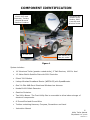
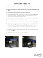
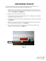
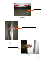
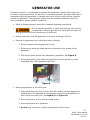
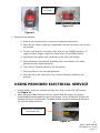
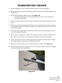
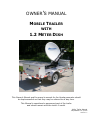
OWNER’S MANUAL
MOBILE TRAILER
WITH
1.2 METER DISH
This Owner’s Manual and the owner’s manual for the Honda generator should
be kept accessible so that they may be referred to at any time.
This Manual is considered a permanent part of the trailer
and should remain with the trailer if resold.
Utility Trailer Manual
Skycasters LLC ©2008
Version 1.7
TABLE OF CONTENTS
SAFETY .............................................................................................. 3
Safety Alerts ...................................................................................... 3
Safety Alert Labels.............................................................................. 3
COMPONENT IDENTIFICATION ........................................................... 4
LEVELING TRAILER ............................................................................ 5
GROUNDING TRAILER ........................................................................ 6
GENERATOR USE ................................................................................ 8
USING PROVIDED ELECTRICAL SERVICE ............................................ 9
DEPLOYMENT OF SATELLITE DISH.................................................... 10
COOLING FAN AND THERMOSTAT ..................................................... 11
REMOVAL OF FRONT UTILITY BOX FOR STORAGE ............................. 11
TRANSPORTING TRAILER ................................................................. 12
TECHNICAL SUPPORT ....................................................................... 13
The information and specifications included in this Owner’s Manual are in effect at the time of
printing. Skycasters LLC reserves the right to change specifications or design at any time
without notice. No part of this Manual may be reproduced without permission from Skycasters
LLC.
2
Utility Trailer Manual
Skycasters LLC ©2008
Version 1.7
SAFETY
Your safety and the safety of others are very important. We have provided operating
procedures and other information on labels and in this Owner’s Manual to alert you to
potential hazards that could hurt you or others. Please use your own good judgment.
SAFETY ALERTS
These symbols warn you of potential hazards that can cause serious injury or death.
Read them carefully. Safety Alert Labels are placed on the trailer at various locations
for your safety. These signal words mean:
DANGER indicates an imminently hazardous situation which, if not
avoided, will result in death or serious injury.
WARNING indicates a potentially hazardous situation which, if not
avoided, could result in death or serious injury.
CAUTION indicates a potentially hazardous situation which, if not
avoided, may result in minor or moderate injury.
SAFETY ALERT LABELS
•
•
•
•
•
Keep hands away from mechanical area of dish.
- When dish is in motion, this area could pinch or crush hands.
Remove generator from utility box to refuel.
- To prevent spillage of gasoline within the utility box that may cause
combustion or fire.
Remove gas can from utility box when generator is in use.
- To prevent possible fire hazard.
RF Radiation Source – Keep Back 10 Feet.
- This satellite dish emits radiation that could be harmful if there is
exposure. Do not stand directly in front of the dish or place any part of
your body between the dish and the electronics feed assembly (attached
to the arm in front of the dish).
- Stand back 10 feet from the trailer in all directions when system is active.
Do not stand or sit on platform or lid of box.
- You are within a restricted area and may interfere with leveling of the
trailer.
3
Utility Trailer Manual
Skycasters LLC ©2008
Version 1.7
COMPONENT IDENTIFICATION
Rear Utility Box
stores 1000-watt
Generator, Toolbox,
Ground Wire and
Gasoline Container
Front Utility Box
contains 3100
Modem, 9000
Controller and
Wireless Router
Ground Rod
Jack Stands (4)
One per corner
Figure 1
System includes:
•
14’ Aluminum Trailer (powder coated white), 2” Ball Receiver, 1000 lb. Axel
•
1.2 Meter iNetVu Satellite Dish with 9000 Controller
•
iDirect 3100 Modem
•
Linksys Wireless Broadband Router (WRT54GS) with SpeedBooster
•
One 2.4 GHz 8dBi Omni Directional Wireless Lan Antenna
•
Honda Eu1000 Watt Generator
•
Gasoline Container
•
Two Utility Boxes. The Front Utility Box is removable to allow indoor storage of
electronic components.
•
8’ Ground Rod and Ground Wire
•
Toolbox containing Hammer, Compass, Screwdriver and Level
•
Instruction Manual
4
Utility Trailer Manual
Skycasters LLC ©2008
Version 1.7
LEVELING TRAILER
In order to ensure proper deployment of the satellite dish, it is important that the
satellite platform be level.
1. Park trailer on even level ground with either side of the trailer facing toward the
South.
2. Place trailer blocks behind tires to prevent it from rolling.
3. Unhitch trailer from vehicle. Deploy one of the two jack stands located toward
the front of the trailer. Lift tongue of trailer until receiver is clear of 2” ball.
Remove safety chains and unplug trailer lights.
4. Unlock all other jack stands and rotate to a vertical position. Lower each jack
stand until contact is made with the ground.
5. Obtain level from toolbox located in the Rear Utility Box. Place level on platform
supporting satellite dish with the level oriented front to back. See Figure 2.
6. Adjust front or rear jack stands until trailer is level front to back. Note: Make
sure the base of all four jack stands (as well as the trailer tires) remain in
contact with the ground for maximum stability. If ground is sloped, you may
need to use additional spacers beneath the jack stands to level the trailer.
7. Place level on platform supporting the satellite dish with the level oriented side
to side. See Figure 3.
8. Readjust jack stands until trailer is level side to side.
9. Repeat process until platform is level in both directions.
Figure 2
Figure 3
5
Utility Trailer Manual
Skycasters LLC ©2008
Version 1.7
GROUNDING TRAILER
In order to protect the electronic equipment and ensure proper orientation, it is
important that the equipment be properly grounded before use.
1. Obtain hammer, ground clamp and flathead screwdriver from the provided
toolbox. Unscrew end cap from tube, which is attached to the ground rod with a
pull rope. See Figure 4 and Figure 5.
2. Remove ground rod by pulling on end cap.
3. Pound ground rod into ground with hammer. Note: A ladder may be needed to
reach the top of the 8’ ground rod.
4. Install ground clamp to ground rod by tightening two screws with a screwdriver.
See Figure 6.
5. Obtain roll of ground wire from utility box. Secure ground wire to ground rod
clamp by tightening the setscrew. See Figure 6.
6. Secure other end of ground wire to frame of trailer close to exhaust port of
generator. Tighten setscrew. See Figure 7.
End Cap
Figure 4
6
Utility Trailer Manual
Skycasters LLC ©2008
Version 1.7
8’ Ground Rod
Figure 5
Ground Rod Clamp with Setscrew
Figure 6
Ground Screw located
on side of trailer frame
Figure 7
7
Utility Trailer Manual
Skycasters LLC ©2008
Version 1.7
GENERATOR USE
If weather permits, it is preferable to operate the generator outside of the utility box
for better cooling and airflow. In the event of inclement weather, the Rear Utility Box is
designed to allow the generator to operate within the utility box with the lid closed to
protect the generator. The generator should only be operated inside the utility box
when dictated by severe weather conditions.
•
Refer to Honda generator manual for detailed operating instructions.
•
Do not operate generator in utility box with gas can in same
compartment. Remove gas can from utility box and place on
level ground away from exhaust port of utility box.
•
Always make sure that the generator is off when checking fuel level.
•
Remove the generator from utility box when refueling.
1. Remove straps securing generator in box.
2. Remove any electrical plugs that are connected to any outlets of the
generator.
3. Disconnect green ground wire attached to generator. See Figure 8.
4. Remove generator from utility box and place on level ground in a wellventilated area. Refill generator with fuel.
Figure 8
•
Returning generator to the utility box.
1. Place generator onto floor of utility box with muffler securely against the
exhaust port. The backside of the generator should be flush against the
back wall of the utility box. See Figure 9 and Figure 10.
2. Secure generator to floor with provided straps.
3. Secure ground wire to generator.
4. Do not plug any power cords to the generator at this time.
8
Utility Trailer Manual
Skycasters LLC ©2008
Version 1.7
Exhaust Port
for Muffler
Figure 10
Figure 9
•
Starting the generator.
1. Refer to the Honda owner’s manual for detailed instructions.
2. Open the air valve on gas cap of generator and turn the vent lever to the
on position.
3. To start cold engine, move the choke lever to the CLOSED position. To
restart a warm engine, leave the choke lever in the OPEN position.
4. Pull starter grip lightly until resistance is felt, then pull briskly.
5. When generator has started, gradually move the choke to the open
position as the engine warms up.
6. Turn the Eco Throttle switch to the on position.
7. Plug the electric cord into the generator.
8. Close the lid of the utility box only if severe weather conditions are
present.
USING PROVIDED ELECTRICAL SERVICE
•
•
Unplug power cord from outside of utility box. Plug in local 120 VAC service.
See Figure 11.
When using provided electrical service, ensure that the power is properly
conditioned/protected against spikes and surges. Power spikes and surges can
damage electronic components. Damage caused by power spikes and surges is
not covered under warranty.
External 120 Volt Inlet on
Front Utility Box
Figure 11
9
Utility Trailer Manual
Skycasters LLC ©2008
Version 1.7
DEPLOYMENT OF SATELLITE DISH
Refer to iNetVu CD for detailed operator instructions.
1. Make sure electrical connections are made to either the generator or from your
local 120-volt service.
2. Remove any tie down straps from the satellite dish.
3. The Linksys router and 3100 iNetVu modem will be on when electrical
connection is made.
4. Press the power button on the 9000 Controller immediately after electrical
connection is complete. It will take several minutes for the 3100 modem to boot
up. The RX and TX lights will blink repeatedly after boot up.
5. The controller will boot up. The word “Maintenance” will display on the LCD
screen. See Figure 12.
6. Do not press “Find Satellite” button on the 9000 Controller at this time. Various
parameters within the controller must first be met. The controller can be
remotely accessed via web interface or VNC Viewer to make sure it is ready to
deploy the dish. Refer to instructions on CD labeled iNetVu. Refer to PDF file
named iNetVu 9000 Controller User Manual.
7. The dish will elevate and move from left to right to lock in on the signal from the
satellite. It may take up to 7 minutes for the system to lock onto the satellite.
All 5 lights on the front side of the 3100 modem will turn steady green when the
system is activated.
Figure 12
10
Utility Trailer Manual
Skycasters LLC ©2008
Version 1.7
COOLING FAN AND THERMOSTAT
•
•
•
Make sure all storage covers on the cooling exhaust vents
are removed.
It is recommended that the thermostat be set between 90°
and 100°F. The fan will operate when temperature inside the
utility box exceeds the preset temperature. See Figure 13.
External vent covers are removable for replacement of
filters.
120 VAC Thermostat
set at 90°F.
Figure 13
REMOVAL OF FRONT UTILITY BOX
FOR STORAGE
The Front Utility Box is designed so that it may be removed from the trailer for indoor
storage. For long-term storage, the electronic components should be stored indoors.
There are two yellow Zerust® capsules placed within the Front Utility Box to provide
further corrosion protection. The capsules can last up to two years.
•
Remove cables from exterior of box.
1. Remove the set of cables labeled RX and TX.
2. Remove the remaining set of cables that are labeled Sensor and Motor
cable.
3. Remove the yellow 120-volt plug from the receptacle.
4. Place all cables into front or rear utility box for storage.
5. Remove all 4-hand knobs that secure utility box to frame of trailer.
Knobs are located inside the utility box on the bottom of the box.
6. Place storage covers over exhaust vents. Close lid of box.
7.
With two people, grab the handles of the box and lift up off
trailer frame and transport to indoor storage.
11
Utility Trailer Manual
Skycasters LLC ©2008
Version 1.7
TRANSPORTING TRAILER
1. Securely tighten all four mounting knobs inside the Front Utility Box.
2. Make sure that the gas can is securely fastened with strap and that the gas cap
is tightened.
3. Secure the generator with both ties. See Figure 10.
• Turn the engine switch and fuel tank cap lever to the “OFF” position to
prevent fuel leakage.
4. Check to make sure that the end cap on the tube that contains the ground rod is
tight.
5. One of the front jack stands toward the front of the trailer will need to remain in
the downward position in order to support the tongue until the trailer is secured
to the tow vehicle.
6. Crank up other 3 jack stands, unlock and rotate into a horizontal position, and
relock in horizontal position.
7. Move vehicle to align the 2” ball to the receiver of trailer. Using remaining front
jack stand, lower receiver onto ball and lock hitch into place with handle.
8. Crank up the base of the remaining jack stand, unlock and rotate into a locked
horizontal position, and relock in horizontal position.
9. Attach the two tow chain hooks to the tow hitch of vehicle. See Figure 14.
10. Connect plug for lights on trailer. Check to make sure that the brake, turn signal
and running lights are operational.
Figure 14
12
Utility Trailer Manual
Skycasters LLC ©2008
Version 1.7
TECHNICAL SUPPORT
Our Advanced Technical Support Team would be pleased to assist you regarding this
equipment.
Telephone:
1 800-268-8502
1 xxx-xxx-xxxx
United States Callers
International Callers
Monday- Friday
Saturday
8:00 a.m. – 8:00 p.m. EST
9:00 a.m. – 5:00 p.m. EST
Your assigned account number is _____________.
13
Utility Trailer Manual
Skycasters LLC ©2008
Version 1.7