1
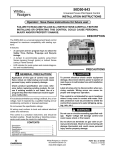
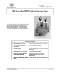
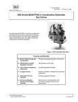
Technical Bulletin VLV
Issue Date 0100
VLV49A Series Universal Replacement Gas Valve
To Terminal 3
To Terminal 5
or Ground
To Terminal 1
Blue
Red
Black
Grommet
Screw B
Screw A
Pilot Tap
Connection
Valve
Inlet
Figure 1: Universal Replacement Gas Valve
Application
The VLV49A Series Universal Replacement Gas Valve is for the
replacement of the valve assembly of an electronic proven pilot spark
ignition control with a valve (i.e., G60 and Q15). They are combination
redundant valves, available with or without a pressure regulator.
These valves can be used on appliances burning natural gas, Liquefied
Petroleum (LP) gas, manufactured gas, mixed gas or LP gas-air mixtures,
including sulfur bearing gases (depending on the regulator selection) at
pressures up to 35 mbar (0.5 psi).
© 2004 BASO Gas Products
Part No. 24-8711-455, Rev. ⎯
1
www.baso.com
Table 1: Specifications
Product
VLV49A Series Universal Replacement Gas Valves
Maximum Operating
Pressure
35 mbar (0.5 psi)
Ambient Temperature
-40 to 80°C (-40 to 175°F)
Electrical Rating
24 VAC, 60 Hz, 0.3 ampere draw
Regulator Adjustment
Range
7.5 to 15 mbar (3 to 6 in. W.C.)
Inlet Pipe Size
1/2 in. NPT
Outlet Pipe Size
3/4 in. NPT
Pilot Outlet
1/8 in.-27 NPT left and right
Wiring Connections
216 mm (8.5 in.) lead wires
Types of Gas
Natural, Liquefied Petroleum (LP), manufactured, mixed,
and LP gas-air mixtures
Accessories
Conversion Kits
Natural gas to LP gas:
Agency Listings
lever-acting regulator Y71GF-4
direct-acting regulator Y71GF-3
None
The performance specifications are nominal and conform to acceptable industry standards.
For application at conditions beyond these specifications, consult BASO Gas Products.
BASO Gas Products shall not be liable for damages resulting from misapplication or misuse
of its products.
Table 2: Universal Replacement Gas Valve Chart
Valve Part Number
2
Regulator Type
VLV49A-600R
Direct-acting regulator
VLV49A-601R
Lever-acting regulator
VLV49A-602R
No regulator
VLV49A Series Universal Replacement Gas Valve Technical Bulletin
Table 3: Replacement Valve Selection Chart
Original Valve/Ignition Part Number
Replacement Valve Part Number
G60CAA-1, 3
VLV49A-602R*
G60CAG-1, 2, 3, 4, 6, 7, 8
VLV49A-602R
G60CAG-9
VLV49A-602R*
G60CBA-1, 3
VLV49A-601R*
G60CBG-1, 3, 4, 9, 10, 11, 14, 16, 17
VLV49A-601R
G60CCA-1
VLV49A-600R*
G60CCG-1
VLV49A-600R
G60CPG-1
VLV49A-601R plus Y71GF-4
G60DBG-1
VLV49A-601R
G60DCG-1, 2, 4
VLV49A-600R
G60QAG-1, 2, 3
VLV49A-602R
G60QAG-1
VLV49A-602R
G60QAK-1
VLV49A-602R
G60QBG-1, 2, 3, 4, 5, 6, 7, 8, 9
VLV49A-601R
G60QBH-1
VLV49A-601R
G60QBK-1
VLV49A-601R
G60QBK-3
VLV49A-601R
G60QBL-1
VLV49A-601R
G60QCG-1
VLV49A-600R
G60QCL-1
VLV49A-600R
G60QCJ-1
VLV49A-600R
G60QDG-1
No Replacement Available
G60QFL-1
VLV49A-602R
G60QHL-1, 2
VLV49A-600R
G60QJL-1
No Replacement Available
G60QLG-1
VLV49A-601R
G60QPL-1
VLV49A-601R plus Y71GF-4
G60QRH-1
VLV49A-601R plus Y71GF-4
G60QRL-1, 2, 3
VLV49A-601R plus Y71GF-4
G60QSL-1
VLV49A-600R plus Y71GF-3
G60QTH-1
VLV49A-601R
G60QTL-1
VLV49A-601R
G60QUL-1
VLV49A-601R
G60RAG-1
VLV49A-602R
G60RBG-1, 2
VLV49A-601R
G60RBG-3
VLV34A-648R
G60RBK-1, 2
VLV49A-601R
G60RCG-2
VLV49A-600R
G60RCJ-1
VLV49A-600R
G60RDG-1
No Replacement Available
G60RDK-1
No Replacement Available
G60RGL-1
VLV49A-601R
G60RHL-1
VLV49A-600R
Continued on next page . . .
VLV49A Series Universal Replacement Gas Valve Technical Bulletin
3
Original Valve/Ignition Part Number
(Cont.)
Replacement Valve Part Number
G60RHP-1
VLV49A-600R
G60RPL-1
VLV49A-601R plus Y71GF-4
G60RSL-1
VLV49A-600R plus Y71GF-3
VLV34A-605
VLV49A-601R
VLV34A-608
VLV49A-602R
VLV34A-609
VLV49A-601R
VLV34A-610
VLV49A-602R
VLV34A-613
VLV49A-602R
VLV34A-614
VLV49A-601R
VLV34A-617
VLV49A-600R
VLV34A-621
VLV49A-600R
VLV34A-623
VLV49A-601R
VLV34A-624
VLV49A-602R
VLV34A-625
VLV49A-601R
VLV34A-626
VLV49A-600R
VLV34A-628
VLV49A-600R
VLV34A-633
VLV49A-601R
VLV34A-636
VLV49A-601R
VLV34A-637
VLV49A-600R
VLV34A-638
VLV49A-602R
VLV34A-639
VLV49A-601R
VLV34A-640
VLV49A-602R
VLV34A-641
VLV49A-602R
VLV34A-642
VLV49A-601R
VLV34A-643
VLV49A-600R
VLV34A-644
VLV49A-600R
VLV34A-645
VLV49A-601R
VLV34A-648
VLV34A-648R
VLV37A-602
No Replacement Available
VLV37A-603
No Replacement Available
VLV41A-600
VLV49A-602R
VLV41A-601
VLV49A-601R
VLV41A-602
VLV49A-600R
VLV41A-605
VLV49A-601R
VLV43A-600
VLV49A-601R
VLV43A-601
VLV49A-602R
VLV43A-602
VLV49A-601R
VLV43A-603
VLV49A-600R
VLV43A-604
VLV49A-600R
VLV43A-605
VLV49A-601R
VLV43A-606
VLV49A-601R
VLV43A-607
VLV49A-602R
VLV43A-608
VLV49A-601R
VLV43A-612
VLV49A-600R
Continued on next page . . .
4
VLV49A Series Universal Replacement Gas Valve Technical Bulletin
Original Valve/Ignition Part Number
(Cont.)
Replacement Valve Part Number
VLV43A-609
VLV49A-601R
VLV43A-610
VLV49A-601R
VLV43A-615
VLV49A-601R
VLV43A-616
VLV49A-600R
VLV44A-600
No Replacement Available
VLV44A-601
No Replacement Available
VLV49A-604R
VLV49A-600R plus Y71GF-3
VLV49A-605R
VLV49A-601R plus Y71GF-4
VLV49A-606R
VLV49A-601R
G96JGA-3 (Q15HAA-1)
VLV49A-601R
* 24 VAC replacement gas valve for original 120 VAC valve. A 24 VAC transformer is
required.
Note:
All replacement valves come set up for use with natural gas. If used on an LP
system, the appropriate Y71 conversion kit must be installed.
•
Y71GF-3
Natural to LP for direct-acting regulators
•
Y71GF-4
Natural to LP for lever-acting regulators
VLV49A Series Universal Replacement Gas Valve Technical Bulletin
5
Installation
IMPORTANT:
!
!
This technical bulletin is intended as a guide for
authorized service personnel installing or servicing
BASO Gas products. Carefully follow all
instructions in this bulletin and all instructions on
the appliance. Limit repairs, adjustments, and
servicing to the operations listed in this bulletin or
on the appliance.
WARNING: Fire or Explosion Hazard. The system must meet
all applicable codes. Improper installation may
cause gas leaks, explosions, property damage, and
injuries.
WARNING: Fire or Explosion Hazard. To prevent leakage of
upstream gas, shut off the gas supply at the main
manual shutoff valve before installing or servicing
the VLV valve.
!
CAUTION:
Equipment Damage Hazard. To prevent damage
to the valve when mounting to the manifold, do not
use a wrench on any surface other than the casting
flats provided at the inlet and outlet ends of the
valve body.
!
CAUTION:
Equipment Damage Hazard. Label all wires prior
to disconnection when replacing the valve. Wiring
errors can cause improper and dangerous operation.
Verify proper operation after servicing.
Perform the following procedure to install the replacement VLV49A
valve.
6
1.
Turn off power to the appliance.
2.
Turn off the gas at the manual shutoff valve adjacent to the appliance.
(If the manual shutoff valve services more than one appliance, be sure
to light the other pilots before leaving.)
3.
With the gas and power to the appliance turned off, disconnect the
power supply (transformer) and the thermostat lead wire at the
ignition control.
VLV49A Series Universal Replacement Gas Valve Technical Bulletin
4.
5.
6.
Disconnect the sensing probe lead from Terminal 4 on the ignition
control.
Disconnect the high voltage cable from the spark transformer.
Disconnect the Pilot Valve 1 and Main Valve 3 leads from the
terminal board or end plug-in Heyco terminals (see Figures 2 and 3).
Terminal Board
Connections
Ground
Terminals
Figure 2: Terminal Board Ignition Control
with Mounting Plate
Ground
Terminals
Heyco Terminal
Connections
Figure 3: Plug-in Heyco Ignition Control
VLV49A Series Universal Replacement Gas Valve Technical Bulletin
7
7.
8.
9.
Remove Screws A and B holding the ignition control assembly to the
valve and plate assembly (see Figure 1). These two screws are located
on the bottom surface of the ignition control assembly.
Remove the ignition control.
Disconnect the pilot burner tubing from the pilot tap connection on
the gas valve (see Figure 1).
10. Verify (when looking on the inlet of the valve) that the location of the
grommet and wire leads on the old valve and new replacement valve
are on the same side.
If they are not on the same side, remove the grommet of the new
replacement valve and insert it into the other side of the mounting
plate (see Figure 4). This allows the placement of the ignition control
spark transformer over the outlet of the valve instead of the inlet.
Remove grommet
and wires from here.
Removable Portion
of Mounting Plate
Removable Portion
of Mounting Plate
Replace grommet
and wires here.
Figure 4: Grommet Locations
11. Remove the old valve from the manifold and install the new
replacement valve. Ensure the gas flows through the valve body in the
direction indicated by the arrow on the valve body. If the valve is
installed with the gas flow opposite the arrow, leakage can occur.
A thread lubricant has been factory applied to the first two or
three threads of the valve inlet and outlet to avoid galling. Use an
approved pipe-joint sealing compound on male threads before
assembling. Take care that excess compound does not work into the
valve and get onto the valve seats. Threads of pipe and nipples must
be smooth and free of tears and burrs.
12. Reconnect the pilot burner tubing at the pilot tap connection.
13. Fasten the ignition control assembly to the valve and plate assembly
with the screws provided with the replacement valve.
14. Break off the portion of the plate that protrudes if it interferes with
surrounding surfaces (see Figure 4).
8
VLV49A Series Universal Replacement Gas Valve Technical Bulletin
15. Reconnect the thermostat leads, the sensing probe lead, and the high
voltage cable according to the labels on the wires. Do not connect
the electrical supply at this time.
a. On grounded versions (part numbers ending with the
letters H, L, G, or J [e.g., G60QBG or G60QBJ]), connect the
black lead wire to one of the ground terminals on the ignition
control. Four ground spade terminals are located just below the
terminal board on terminal board models (see Figure 2) or in a
square arrangement on the end of the plug-in Heyco models
(see Figure 3).
On ungrounded versions (part numbers ending with a K
[e.g., G60QBK]), connect the black lead wire to Terminal 5 on
the ignition control.
On systems using G600 ignition controls, connect the black lead
wire to a ground terminal on the ignition control.
b.
Connect the blue lead wire to Terminal 1 on the ignition control.
IMPORTANT:
To permit verification of pilot operation, do not connect
the red lead wire to any terminal at this time.
16. Check for leakage.
a.
Open the pressure connection between the manual shutoff valve
and the VLV valve.
b.
Connect air tubing with a maximum pressure of 1-1/2 times the
valve’s maximum operating pressure (as indicated on the valve)
to the opened pressure connection.
c.
Paint all valve body connections with a rich soap and water
solution.
If bubbles occur, this is an indication of a leak. To stop a leak,
tighten joints and connections. Replace the part if the leak
cannot be stopped.
If bubbles do not occur, remove the air tubing and close the
pressure connection.
VLV49A Series Universal Replacement Gas Valve Technical Bulletin
9
17. After installation of the replacement valve is complete, except for the
attachment of the red lead wire, turn on the gas at the manual
shutoff valve.
a.
Reconnect the power supply lead wire to the ignition control and
turn the power On.
b.
Set the thermostat to the highest setting. The pilot valve will
open, spark will be energized, and the pilot will light.
c.
Test for gas leaks in the pilot line with a soap solution.
d.
After the check is complete, turn off the power and connect the
red lead wire to Terminal 3 on the ignition control.
18. Turn on the power and set the thermostat to the desired setting.
10
VLV49A Series Universal Replacement Gas Valve Technical Bulletin
Regulator
Adjustment
IMPORTANT:
!
All adjustments must be made in conjunction with
the gas appliance and in accordance with the
appliance manufacturer’s instruction. Only
authorized personnel should make adjustments.
WARNING: Explosion Hazard. The minimum flow rate of the
valve must not be adjusted below the minimum safe
working rate of the appliance.
The pressure regulator is adjustable and has been factory set. If a different
setting is desired, follow these instructions.
1.
Shut off all gas to the appliance.
2.
Turn the thermostat to the lowest setting or Off position.
3.
Remove the pressure tap plug at the valve outlet or in the manifold
pipe downstream of the valve.
4.
Install a manometer or pressure gauge suitable for measuring the
desired orifice pressure.
5.
Remove the seal screw at the end of the regulator stack.
6.
Turn the gas on and place the thermostat at the highest setting to
cycle the ignition system.
7.
Allow the system to stabilize. Adjust the screw in the regulator stack
to the desired reading on the manometer. (Turn clockwise to increase
the outlet pressure and counterclockwise to reduce the outlet
pressure.)
8.
Reinstall the seal screw, which incorporates the proper size hole for
venting to the atmosphere. (It may be necessary to cycle the valve
several times to verify the desired outlet pressure.)
9.
Turn off the gas supply and place the thermostat at the lowest setting.
10. Remove the pressure manometer and reinstall the pressure tap plug.
11. Turn the gas on and set the thermostat to the desired setting.
12. Check for leaks at the pressure tap plug with a soap solution before
leaving the site.
VLV49A Series Universal Replacement Gas Valve Technical Bulletin
11
Checkout
Procedure
!
WARNING: Fire or Explosion Hazard. Avoid personal injury
or property damage by making sure the valve
functions properly and there are no gas leaks.
Follow this checkout procedure before leaving the
installation.
Make sure all components are functioning properly by performing the
following test:
Repairs and
Replacement
1.
Test for leaks on all pipe joints and connections upstream of the gas
valve with a soap solution.
2.
Turn the thermostat to a low setting.
3.
Turn on the gas and purge the gas lines of all air.
4.
Turn the thermostat to a high setting. The appliance should operate in
accordance with the manufacturer’s specified sequence of operation.
5.
Test for leaks on all pipe joints and connections downstream of the
gas valve with a soap solution.
6.
Turn the thermostat down for at least 30 seconds and then back up
again. Verify successful ignition at least three times before leaving
the installation.
The VLV49A replacement valves are not field repairable. Do not
attempt field repairs. For a replacement valve, contact the nearest
BASO Gas Products distributor.
1007 South 12th Street
PO Box 170
Watertown, WI 53094
1-877-227-6427 (1-877-BASOGAS)
12
VLV49A Series Universal Replacement Gas Valve Technical Bulletin
www.baso.com
Printed in U.S.A.