1
Product Bulletin
Issue Date
February 12, 2009
G93 Series BASOTROL® Combination Automatic
Gas Valves
The G93 Series BASOTROL® Gas Valve combines the
automatic pilot valve, pressure regulator and automatic
main valve functions in one valve. Typical applications
include central heating units, unit heaters, commercial
clothes dryers and similar applications.
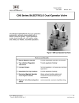
Figure 1: G93 Combination Gas Valve
Features and Benefits
Bipolar Magnetic Operator
Construction
Provides dependable operation and long life
200,000 Btu/hr (59 kW)
Regulation Capacity
Standardizes on one valve
Top or Bottom Regulation
Adjustment
Provides application flexibility
Compact Design
Permits installation in dimensionally restricted
applications
Selectable Pilot Tap
Positions
Provides application flexibility
Numerous Magnetic
Operator Cover Styles
Available
Allows various mounting options and
connection choices to best suit your
requirements
© 2009 BASO Gas Products
Code No. BASO-PB-G93, Rev. B
1
www.baso.com
P roduct Overview
Application
Magnetic Operator Cover Styles
The G93 valves are suitable for use with natural gas,
Liquefied Petroleum (LP) gas or LP gas-air mixtures,
at pressures up to 0.5 psi (35 mbar) and are suitable
for operation over a temperature range of 32 to 155°F
(0 to 68°C).
An aluminum magnetic operator cover with conduit
hub and 30 in. (762 mm), 18 AWG stranded lead wires
are supplied as standard on all line voltage models.
The leads and hub position may be located at the top,
over the outlet, on the right side or on the left side of
the valve. Lead wires with 1/4 in. (6.35 mm) quickconnect terminals are also available.
Note:
This unit should be used only in applications
that are within the limitations and provisions of
the applicable American National and/or
Underwriters Laboratories® (UL) standards.
Description
The G93 valves are supplied with a standard magnetic
operator and are 100% shutoff valves when the pilot is
extinguished. Bipolar construction of the operator
reduces the possibility of the valve sticking in the open
position from residual magnetism or from mechanical
interference.
A leak limit orifice is supplied as standard on valves
with a regulator stack.
Valve Constructions
The G93 series is available with 1/2 x 1/2 in. body
connections with a 25, 120 or 240 VAC 2-wire
magnetic operator. Some models are also available
with a 208/240 VAC operator. Refer to the Ordering
Information section for more information.
Additionally, the G93 series is available with other
optional configurations.
Pressure Connections
The G93 valve is available with 1/8-27 NPT pressure
taps when required (see Figure 4). Contact BASO Gas
Products for details and ordering information.
2
The UL Listed steel operator cover is available with a
top conduit hub only.
A plastic magnetic operator cover with 1/4 in.
(6.35 mm) quick-connect male terminals is supplied as
standard on all voltage models.
Contact BASO Gas Products for details and ordering
of magnetic operator cover style and wiring
requirements.
Pilot Gas
G93 valves are available with internal pilot gas flow.
Rotor “B” Valve
Figure 2 illustrates a typical installation showing a rotor
“B” valve.
A rotor “B” valve (for pilot flame) with pilot flow adjuster
is available. Various outlet positions are available.
Contact BASO Gas Products for details and ordering.
Regulator/Pilot Tap Options
The G93 is designed for various configurations. The
top adjust or bottom adjust regulator and right or
left-hand pilot tap options take advantage of space or
access limitations.
G93 Series BASOTROL Combination Automatic Gas Valves Product Bulletin
Conduit
Connector
BASOTROL
Magnetic Operator
Power
Source
Thermostat
Reset Button
BASO Power Unit
Shutoff
Valve
Pilot Burner
Gas Line
Thermocouple
Lead
Seal Screw
Figure 2: Typical Installation for Internal Pilot Gas Flow
Power Source
Conduit
Connector
Thermostat
Transformer
BASOTROL
Magnetic Operator
Reset Button
Rotor
“B” Valve
Adjustment
Knob
Baso Power Unit
"A" Valve
Pilot Burner
Gas Line
Thermocouple Lead
Figure 2: Typical Installation Showing Internal Pilot Gas Flow and Rotor “B” Valve
M ounting
Series G93 valves may be mounted on a horizontal
manifold with the magnetic operator pointed up
(vertical) or in a position not exceeding 90° from
vertical. The valve may also be mounted on a vertical
manifold in any position around its axis. See Figure 3.
90º
90º
Horizontal mounting limited
to 90º from upright.
Vertical mounting may
be 360º around its axis
with the gas flow either
up or down, but always in
the direction of the arrow.
Figure 3: Mounting Positions
G93 Series BASOTROL Combination Automatic Gas Valves Product Bulletin
3
D imensions
Pressure Tap
Position No. 1
D
A
Pressure Tap
Position No. 2
Pressure Tap
Position No. 3
C
B
Figure 4: Lever-acting Regulator Model Dimensions Showing
Optional Pressure Tap Positions
Table 1: Dimensions
A Height
B Width
C Length
D Height
Series Number
in.
mm
in.
mm
in.
mm
in.
mm
Top Adjust G93
4.84
123
3.42
87
4.23
107
3.19
80
D
A
B
C
Figure 5: Direct-acting Regulator Model Dimensions
Table 2: Dimensions
A Height
Series Number
Bottom Adjust G93
4
B Width
C Length
D Height
in.
mm
in.
mm
in.
mm
in.
mm
5.66
144
2.66
67
4.23
107
3.19
80
G93 Series BASOTROL Combination Automatic Gas Valves Product Bulletin
R ange of Regulation
Table 3: Range of Regulation
QMAXIMUM
QMINIMUM
Model
All G93
Notes:
cf/h
m3/h
cf/h
m3/h
20
0.57
200
5.7
3
1 m /h = 10.67 kW (1 cf/h = 1,000 Btu/hr) natural gas at 0.64 sp gr
For LP flow rate, see Figure 6.
O rdering Information
G 9
3
_
_ _
-
_
_
Customer-specific Requirements
Letter
A=
B=
L=
Regulator/
Pilot Flow
Top Adjust
(3 to 6 in. W.C.)
7.5 to 15 mbar
Top Adjust
(3 to 6 in. W.C.)
7.5 to 15 mbar
Bottom Adjust
(3 to 6 in. W.C.)
7.5 to 15 mbar
Rotor “B” Valve
No
Yes
No
Letter
Voltage
A=
120V, 60 Hz
B=
240V, 60 Hz
G=
25V, 60 Hz
S = 208/240V, 60 Hz
Letter
A=
*H =
Capacity Rating
at 1” Pressure Drop
Btu/hr
kW
Inlet/Outlet
in. NPT
190,000
166,000
56
48
1/2 x 1/2
1/2 x 1/2
*Not CSA Recognized
The presence of a particular construction in this information does not guarantee its availability. Consult BASO Gas Products for
available constructions.
Figure 7: Ordering Matrix
G93 Series BASOTROL Combination Automatic Gas Valves Product Bulletin
5
T echnical Data
Product
Maximum Operating
Pressure
Valve Body
Permissible Ambient
(Surface) Temperature
Available Magnetic
Operator Cover Styles
Electrical Rating
Recommended
Thermocouple Lead
Lengths
Wiring Connections
Regulator Adjustment
Inlet and Outlet Body
Connections
Types of Gas
Accessories
Packaging
Bulk Pack Quantity
Bulk Pack Weight
Agency Listing
Specification Standards
G93 Series BASOTROL Combination Automatic Gas Valve
0.5 psi (35 mbar)
Aluminum
CSA:
32 to 155°F (0 to 68°C)
UL:
32 to 125°F (0 to 52°C)
Aluminum side conduit hub
Aluminum top conduit hub
Aluminum top without conduit hub
Aluminum side outlet with eyelet
Steel top conduit hub
Plastic with 1/4 in. (6.35 mm) male quick-connect terminals
25 VAC, 60 Hz, 0.3 ampere draw
120 VAC, 60 Hz, 0.05 ampere draw
240 VAC, 60 Hz, 0.03 ampere draw
208/240 VAC, 60 Hz, 0.037 ampere draw
K15: 12 to 48 in. (305 to 1,220 mm)
K16: 12 to 72 in. (305 to 1,830 mm)
K19: 18 to 72 in. (457 to 1,830 mm)
1/4 in. (6.35 mm) male quick-connect terminals, or
30 in. (762 mm) lead wires (other lengths are optional)
3 to 6 in. W.C. (7.5 to 15 mbar), top and bottom adjust regulator, natural gas
6 to 12 in. W.C. (15 to 30 mbar), top adjust regulator, LP gas
8 to 12 in. W.C. (20 to 30 mbar), bottom adjust regulator, LP gas
1/2 x 1/2 in. NPT
Natural, Liquefied Petroleum (LP) or LP gas-air mixtures
Conversion Kits: Natural gas to LP gas:
top adjust regulator
Y71GF-4
bottom adjust regulator
Y71GF-3
LP gas to natural gas:
top adjust regulator
Y71QH-2
bottom adjust regulator
Y71QH-3
Bulk pack supplied to original equipment manufacturer (individual pack optional).
32
51 lb (23 kg)
CSA Certificate Number 229521-1656066 (excludes G93H_ _)
UL Recognized File Number MH2926
ANSI Z21.78, CSA 6.20
UL Standard 372 and 429
Performance specifications are nominal and conform to acceptable industry standards. All agency certification of BASO products is performed
under dry and controlled indoor environmental conditions. Use of BASO products beyond these conditions is not recommended and may void
the warranty. Product must be protected if exposed to water (dripping, spraying, rain, etc.) or other harsh environments. The original
equipment manufacturer or end user is responsible for the correct application of BASO products. Consult BASO Gas Products LLC for
questionable applications. BASO Gas Products LLC shall not be liable for damages or product malfunctions resulting from misapplication or
misuse of its products.
Refer to the G93 Series BASOTROL® Combination Automatic Gas Valve Installation Instructions (BASO-INS-G93) for necessary information
on the installation, use, and servicing of this product.
1007 South 12th Street
PO Box 170
Watertown, WI 53094
1-877-227-6427 (1-877-BASOGAS)
6
G93 Series BASOTROL Combination Automatic Gas Valves Product Bulletin
www.baso.com
Printed in U.S.A.