1
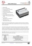
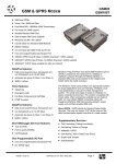
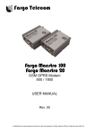
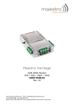
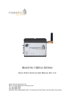
GSM / GPRS MODEM • • • • • • • • • • • • GSM20 GSM and GPRS Voice / Fax / SMS and Data Dual Band 900 / 1800MHz GSM Transmission Full voice call, SMS support Accepts Standard SIM Card Miniature size 88 x 60 x 26mm Can Be Used On Standard GSM Network RS232 Interface AT command set (GSM 07.05 and 07.07) GPRS Class B Class 2 (28.8kbps download/14.4bps upload). One user programmable input/Output Port Integral SIM Card Holder Data/Fax features: • • • Data circuit asynchronous, transparent and non transparent up to 14,400 bits/s Automatic fax group 3 (Class 1 and Class 2) MNP2, V.42bis Voice features: • • • • Telephony Emergency calls Full Rate, Enhanced and Half Rate DTMF Function Data/Fax features: • • • • Data circuit asynchronous, transparent and non transparent up to 14,400 bits/s Automatic fax group 3 (Class 1 and Class 2) MNP2, V.42bis Short Messages Services features: • • • Text and PDU Point to point (MT/MO) About GPRS: GPRS stands for General Packet Radio Services. The user can remain "ON" all the time and the data Communication speed can rival with that of a cable modem. Cell Broadcast GSM Supplementary Services : • • • • • A Miniature "Plug And Play" dual band GSM modem. It can be directly connected to the serial port of a desktop or notebook computer through the RS232 interface. A standard SIM card can be inserted in the integral card holder within the metal enclosure. The Modems metal casing makes it an appropriate solution for tough applications such as Telemetry, Wireless Local Loop (payphones) or as part of a fleet management system. Its small size makes it simple to integrate in a space constraint environment. The modem is supplied with power cable, other accessories available are and antenna (with 1m coax cable), RS232 connecting cable with Telephone interface and a DIN Rail mounting adaptor Call Forwarding -Calling Line Identity One Programmable Input / Output Port : • One user programmable input/Output Port (3V CMOS logic) Call Barring -Advice of Charge Multiparty -USSD Call Waiting / Hold -Closed User Group Explicit Call Transfer DS020-1 Nov 02 2003 REG No 277 4001, ENGLAND. Page 1 GSM / GPRS MODEM GSM20 Technical Specifications Max Storage Temperature Max Operating Temperature -10°C to +70°C, 0°C to +55°C Dimensions Weight 88mm x 60mm x 26mm 100grams Electrical Characteristics Min Supply Voltage Supply Current : In Communication peak in communication idle mode idle mode with RS232 power saving Typical 5 Max Units V 32 450 2.5 25 13 mA A mA mA Interfaces : SIM holder (integrated Drawer, accepts standard SIM card) 15 pin Sub-D type connector (for serial and audio connection) 4-pin power supply connector (micro-FITTM) SMA antenna connector (50 ohm) Ordering Information Part No GSM20 GSM20-Ant GSM20-CAB232 GSM20-DINRL Description GSM GPRS Modem, dual Band Antenna for GSM20 RS232 Cable Interface DIN Rail Mount For more information or general enquiries, please call; R F Solutions Ltd., Unit 21, Cliffe Industrial Estate, Lewes, E. Sussex. BN8 6JL. England. Email : [email protected] Tel: +44 (0)1273 898 000 http://www.rfsolutions.co.uk Fax: +44 (0)1273 480 661 RF Solutions is a member of the Low Power Radio Association. Information contained in this document is believed to be accurate , however no representation or warranty is given and no liability is assumed by R.F. Solutions Ltd. with respect to the accuracy of such information. Use of R.F.Solutions as critical components in life support systems is not authorised except with express written approval from R.F.Solutions Ltd. DS020-1 Nov 02 2003 REG No 277 4001, ENGLAND. Page 2 GSM GPRS Modem 900 / 1800 USER MANUAL Rev. 02 4 Oct 2002 1 CONTENTS SAFETY PRECUTIONS CHAPTER 1 INTRODUCTION CHAPTER 2 INSTALLATION CHAPTER 3 WORKING WITH MAESTRO 20 CHAPTER 4 TROUBLE SHOOTING CHAPTER 5 SPECIFICATION CHAPTER 6 APPENDIX -1- 2 Safety Precautions The modem generates radio frequency (RF) power. When using the modem care must be taken on safety issues related to RF interference as well as regulations of RF equipment. Do not use your phone in aircraft, hospitals, petrol stations or in places where using GSM products is prohibited. Be sure that the modem will not be interfering with nearby equipment. For example: pacemakers or medical equipment. The antenna of the modem should be away from computers, office equipment, home appliance, etc. Always keep a minimum safety distance of the antenna from human body. Do not put the antenna inside metallic box, containers, etc. Check for any regulation or law authorizing the use of GSM in vehicle in your country before installing the modem Install the modem by qualified personnel. Consult your vehicle dealer for any possible interference of electronic parts by the modem. Be careful when the modem is powered by the vehicle’s main battery. The battery may be drained after extended period. Protecting your modem To ensure error-free usage, please install and operate your modem with care. Do remember the following: Do not expose the modem to extreme conditions such as high humidity/rain, high temperatures, direct sunlight, caustic/harsh chemicals, dust, or water. Do not try to disassemble or modify the modem. There is no user serviceable part inside and the warranty would be void. Do not drop, hit or shake the modem. Do not use the modem under extreme vibrating condition. Do not pull the antenna or power supply cable. Attach/ detach by holding the connector. Connect the modem only according to the instruction manual. warranty. In case of problem, please contact authorized dealer. -2- Failure to do it will void the 3 CHAPTER 1 INTRODUCTION Maestro 20 is a ready-to-use GSM modem for voice, data, fax and SMS services. It also supports GPRS (Class 2) for hi-speed data transfer. Maestro 20 can be easily controlled by using AT command for all kinds of operations. With standard 9-pin RS232 port and telephone-like audio plug the Maestro 20 can be set up with minimal effort. 1.1. Package The Maestro 20 package should include the following: 1.Maestro 20 x 1 2. Power cord with fuse x 1 3. Safety note x 1 1.2. INTERFACES S IM h o l d e r e j e c t b u tto n S M A fe m a l e a n te n n a c o n n e c to r S IM h o l d e r S ta tu s i n d i c a to r 15 pin Sub-D Female Connector (RS232/Audio) 4-PIN connector (Power, Input / Output) -3- 4 1.2.1. Status indicator The LED will indicate different status of the modem: - off Modem switched off - on Modem is connecting to the network - flashing slowly Modem is in idle mode - flashing rapidly Modem is in transmission/communication (GSM only) 1.2.2. SMA female antenna connector - Connect this to an external antenna with SMA male connector. Make sure the antenna is for the GSM900/1800 frequency with impedance of 50ohm, and also connector is secured tightly. - 1.2.3. 15-PIN D-SUB Female connector (RS232 / Audio) The connector provides serial link and audio link to the modem. Pin number 1 2 3 4 5 6 7 8 9 10 11 12 13 14 15 Name DCD TX BOOT MICROPHONE (+) MICROPHONE (-) RX DSR DTR GND SPEAKER(+) CTS RTS RI RESET SPEAKER(-) EIA designation Data Carrier Detect Transmit Data Receive Data Data Set Ready Data Terminal Ready Ground Clear to Send Request to Send Ring Indicator -4- Type Output Input Input Output Output Output Output Input Ground Output Output Input Output Input Output 5 Specification of microphone and speaker to be connected : Parameters phone current @2V / 2K Ohm phone input level Min Typical 0.5 mA Max Remark 100 mVpp ker output current 150 Ohm/ 1nF ker impedance 16mA 32ohm 1.2.4. 4-PIN connector (Power, Input / Output) Pin assignment of 4-pin connector Pin number 1 Name I/O 2 ~INTR 3 4 POWER POWER+ Functions Input / Output port Interrupt function triggered by pulling this pin to ground or LOW level; reserved for additional functions with new firmware DC power negative input DC power positive input A cable, included in the package shall be used for power supply connection: Connector Micro-Fit 3.0 Fuse holder Fuse rating : -5- Stripped wire 6 I/O Parameters LOW voltage HIGH voltage ut max. sink current Min Typical Max 0.5V 5V 10mA Remark Typical Max 0.5V Remark ered by pulling this pin to LOW ; otherwise leave it open 3V INTR Parameters LOW voltage Min 0 * Please refers to Chapter 6 Appendix for using I/O and INTR signals. -6- 7 CHAPTER 2 INSATLLATION 2.1 Mounting the modem Use 4pcs of 3mm dia meter screw to mount the modem When using optional DIN rail mounting bracket : Insert the mounting bracket to the grooves of the modem. Then mount the modem with screws on the hole of bracket. 2.2 Install the SIM card Use a ball pen or paper clip to press the SIM holder eject button. The SIM holder will come out a little. Then take out the SIM holder. Note : DO NOT pull out the SIM holder without pushing the ejector. Put the SIM card to the tray, make sure it has completely sit on the tray. Put the tray back into the slot. 2.3 Connect the external antenna (SMA type) Connect this to an external antenna with SMA male connector. Make sure the antenna is for the GSM900/1800 frequency with impedance of 50ohm, and also connector is secured tightly. Note : Please use antenna designed for GSM 900/1800 Mhz operation. Incorrect antenna will affect communication and even damage the modem. 2.4 Connect the DC power supply Connect the open ending of the included power cord to a DC supply. Refer to the following for power supply requirement. Power Supply Requirement: Parameters Supply voltage Peak current at 5V supply Average current at 5V supply in idle mode Average current at 5V supply in idle mode & RS232 power saving activated -7- Min 5V Typical 13.2V Max 32V 2.5A 35mA 13mA 8 Connect the connector to the modem. The modem will turn on automatically. The status indicator on the modem will be lit when power on. After a few seconds it will go flashing slowly (registered to the network successfully refer 1.2.1). 2.5 Connect the modem to external device You can use the optional RS-232 cable to connect the modem’s SUB-D connector to external controller/computer. Chapter 3 describes how to communicate with the modem soft in Microsoft WindowsTM envoirnment. -8- 9 CHAPTER 3 Working with Maestro 20 3.1. Checking the modem (using Microsoft WindowsTM HyperTerminal as example) 3.1.1. On the first time power-up you can use terminal software to communicate with the modem through an RS-232 serial Port. Following Examples are using the HyperTerminal in Windows 98. 3.1.2. On Windows 98, start the HyperTerminal program. Assign a name for a new session. -9- 10 3.1.3. Choose the correct Com port and baud rate settings (9600bps, 8bits, no paritybit, 1 stop bit) . 3.1.4. On the terminal screen, type “AT” to check the “OK” response from the modem - 10 - 11 3.2. Basic Operation : Followings are examples of some AT commands. Please refer to the AT Command document for a full description. Note : Issue AT+CMEE=1 to have extended error code (+CME ERROR) Description AT commands AT+CREG? Network Registration Checking CREG=<mode>,1 CREG=<mode>,2 CREG=<mode>,0 Receiving signal strength Receiving an incoming call AT+CSQ Comments Modem response Modem registered to the network Registration lost, re-registration attempt Modem not registration on the network, no registration attempt +CSQ: 20,0 The first parameter has to be at least 15 for normal communication RING An incoming call is waiting ATA Answer the call OK Don’t forget the « ; » at the end for « voice » call ATD1234567; Communication established OK Make a call CME ERROR : 11 CME ERROR : 3 Make an emergency ATD 112; call OK Communication loss NO CARRIER PIN code not entered (with + CMEE = 1 mode) AOC credit exceeded or a communication is already established Don’t forget the « ; » at the end for « voice » call ATH Hang up OK AT+CPIN=1234 PIN Code accepted OK Enter PIN code +CME ERROR : 16 +CME ERROR : 3 Saves parameters in non-volatile memory Incorrect PIN Code (with +CMEE = 1 mode) PIN already entered (with +CMEE = 1 mode) AT&W The configuration settings are stored OK - 11 - 12 CHAPTER 4 Troubleshooting 4.1 The modem’s LED does not light : Check if the modem has connected to a 6-32V power supply properly Check if the power connector is properly inserted Check the fuse on the power cord 4.2 The modem does not response to the terminal program Check if the RS-232 cable has been connected properly Check if your program has proper setting. Factory setting of the modem is: 9600bps 8 data bits no parity bit 1 stop bit - 12 - 13 CHAPTER 5 Specifications Dualband GSM 900 / 1800 Mhz Support Data, SMS, Voice and Fax Max Power Output: 2W(900Mhz), 1W(1800Mhz) Group 3 FAX support (Class 1 and 2) GPRS Class B Class 2 (28.8kbps download/ 14.4kbps upload) at maximum speed. SimToolKit Class 2 AT command set (GSM 07.05, GSM 07.07 and WAVECOM proprietary) Power requirement : Input Voltage: 5V to 32V DC MAX Current at 5V : 450mA in communication 2.5A peak in communication 35mA in idle mode 13mA in idle mode with RS232 power saving Interfaces : SIM holder 15 pin Sub-D connector (serial and audio connection) 4-pin power supply connector SMA antenna connector (50 ohm) Dimensions: Overall size : 88mm x 60mm x 26mm Weight : 100g Temperature range: -15oC to +50oC operating -20oC to +65oC storage - 13 - 14 CHAPTER 6 Appendix 6.1 Factory settings The modem has the following factory settings. Please refer to the AT command document for the meaning of each setting. Related AT commands AT+IPR AT+IFC AT+ICF ATE AT&C AT&D ATQ ATV AT&S ATS0 AT+CLIP AT+CRLP AT+CSCS AT+CMGF AT+CSMP AT+CNMI Factory Settings 9600 2,2 3,4 0 1 1 0 1 1 0 0 “PCCP437” 1 1,67,0,0 0,0,0,0 Description DTE-DCE data rate DTE-DCE flow control DTE-DCE character framing ECHO DCD signal DTR signal Result code suppression Response format DSR signal Auto answer Calling line ID presentation Calling line ID restriction Message format Test mode parameters New message indication 6.2 Input / Output port This port can be configured as either an input one or an output one. To configure it as an input port, first issue AT+WIOW=2, 0 to disable the output port. Use AT+WIOR=1 to read the status of this input port. Response +WIOR: 0 represent Logic HIGH (>3V); Response +WIOR: 1 represent Logic LOW (<0.5V) To use it as an output port, issue AT+WIOW=2,1 will turn it on and it will drain current to ground. The current is recommended not to exceed 10 mA. Issue AT+WIOW=2,0 will turn it off. 6.3 RS232 AUTO-ONLINE mode (power saving) When being in the AUTO-ONLINE, the RS232 transceiver will shutdown most of its hardware to save power if it does not detect a valid input for more than 100uS. The RS232 transceiver will wake up when valid input is detected again. By default, the RS232 transceiver is put in AUTO-ONLINE. This mode can be turned off by issuing AT+WIOW=4,1. - 14 -