1
StoreX Series
User Manual V1.05E
28.02.02 / CMa
LiCONiC AG
FL-9485 Nendeln
Fürstentum Liechtenstein
User Manual
for
StoreX
Robotic Storage
Date: 04.12.A1
LiCONiC
Version:1.05 E
D:\Products\STX\Stx40\STX_UE\Stx_ue05.doc
Author: C. Malin
1/1
Table of Content
1
2
3
THE STOREX-40 FAMILY
4
1.1 StoreX Instruments
1.2 StoreX Handler
1.3 STX Climate Options
1.3.1 StoreX-40 IC
(no cooling system)
1.3.2 StoreX-40 HC
(wet cooling system)
1.3.3 Stroex-40 DC
(dry cooling system)
1.4 STX Configurations
1.4.1 Table Top
1.4.2 Copper Climate Chamber
4
5
6
6
6
6
6
6
6
7
7
7
ACCESSOIRES
8
9
9
10
10
11
11
12
12
13
13
14
14
14
14
14
14
14
14
TRANSPORT AND INSTALLATION
15
3.1
3.2
3.3
3.4
3.5
3.6
4
8
2.1 STX Cassettes
2.2 STX Transferstations
2.2.1 Standard Transferstation
2.2.2 Turn Station
2.2.3 Swap Station
2.3 Shuttle Station
2.3.1 MTP (Standard) Transfer Plate
2.3.2 NTP (Nano Titer Plate) Transfer Plate
2.3.3 Transfer Plate Sensor
2.3.4 Active Plate Alignment
2.4 Bar Code Reader
2.5 Gas Options
2.5.1 RH-Option
2.5.2 CO2 Option
2.5.3 O2 Option
2.5.4 Nitrogen Option
2.6 UHS (Ultra High Speed) Option
2.7 Scheduler
2.8 Customized Color
Unpacking the Instrument
Installation of the Instrument
Transfer Station Position
Installation and Removal of StoreX Handling
Electrical Connections
Communication Connections
MANUAL OPERATION
25
Front Door
4.2 Glass Door
4.3 Cassettes
4.4 Incubation Liquid
4.5 Power-On System
4.6 Alarm System
4.7 Temperature Settings
4.8 Defrost
5
25
26
27
30
31
32
32
32
REMOTE OPERATION
34
5.1 RS 232 Configuration
5.2 Command Transmission Procedure
5.2.1 Break Signal
5.2.2 Command Syntax
5.2.3 Open / Close Communication
5.2.4 Controller Error Messages
5.2.5 System Status
LiCONiC
15
17
20
21
21
22
D:\Products\STX\Stx40\STX_UE\Stx_ue05.doc
34
34
34
35
36
38
38
2/2
5.3 Commands
5.3.1 Basic Commands
5.3.2 Extended Commands
5.4 Handling Status / Error Messages
5.5 Program Examples
6
7
8
UTILITY SOFTWARE
53
6.1.1
6.1.2
6.1.3
6.1.4
6.1.5
6.1.6
6.1.7
53
54
55
55
56
56
56
Direct Commands
Monitor Flags
Macros
Teach Positioning Times
Random Positioning
Random Access Cycles
Random Fast Access
TROUBLESOOTING
MAINTAINANCE
8.1
8.2
9
39
39
42
44
49
57
58
Cleaning
Tension
60
60
TECHNICAL DATA
9.1
9.2
9.3
9.4
61
Mechanics
Electronics
Pneumatics
Dimensions
LiCONiC
61
61
61
61
D:\Products\STX\Stx40\STX_UE\Stx_ue05.doc
3/3
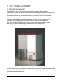
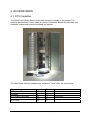
1 THE STOREX-40 FAMILY
1.1 StoreX Instruments
The StoreX 40 Series is the first compact Climate Storage with integrated
Handling that covers the whole range of climate in laboratory applications. The StoreX
Series not only covers a wide temperature range it also offers storage and
processes from ultra-dry to extreme humidity. A variety of gas option is available.
All StoreX units have the same compact dimensions. StoreX have a user
front door which allows comfortable and easy access for manual operation. The
internal Glass Door allows visual inspection of the content and operation of
the system without disturbing the internal climate. Removable cassettes make
the use of the StoreX even simpler and more efficient. Cassettes are
available for all common plate types.
The modular mechanical design in combination with extremely simple commands ease
the integration of the StoreX into any environment. A growing number of accessories is
available for the StoreX Series.
LiCONiC
D:\Products\STX\Stx40\STX_UE\Stx_ue05.doc
4/4
The combination of environmentally controlled Storage and Automatic Plate Exchange
Capability make StoreX the Rex (Latin: king) of storage in laboratory applications.
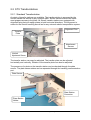
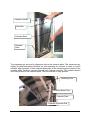
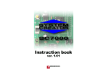
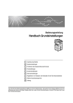
1.2 The StoreX Handler
Inside the StoreX climate chamber there is a handling system that allows
random transport of plates. Plates can be moved internally as well as
transferred to an form the environment. Access times are short and the internal
climate is kept stable even at short time periods between accesses.
Plate Lift
Lift Assembly
Plate Shovel
Cassette
Cassette Plate
A Handler (4) is used for vertical transport as well as loading and unloading of goods.
The Handler consists of a Vertical Positioning Drive (40) , a Turn Drive (42) and a
Shovel Drive (43). The Handler has a number of vertical positions which is determined
by the number of cassette levels and the loading or unloading level.
A stepper motor is used for vertical positioning of the Handler. All vertical positions
are defined by a z-Initiator (15) and the software z-Offset (DM20). The level height is
determined by the number of steps of height. The actual travel path to a certain
cassette level calculated by multiplying the level (DM5) by the pitch (DM21) and then
adding the z-Offset (DM20). The z-positions of the Transfer Station are stored in Data
Memories (DM22, DM24).
The Handler is not only used for vertical transport of the goods, it is also used to pick
and place plates in the cassettes and to get from or put plates on the Transfer Station.
LiCONiC
D:\Products\STX\Stx40\STX_UE\Stx_ue05.doc
5/5
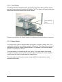
The pick- / place- and get- / put action are vertical movements at extended shovel.
Beware the difference in vertical travel for pick- / place movement (DM21), get
movement (DM26) and put movement (DM28).
The Turn Drive is used to face the Shovel towards the Transfer Station or towards the
desired cassette. The Turn Drive may be positioned at three turn positions. The
position at left cassette id stored in Data Memory DM80, the turn position at the right
position in Data Memory DM81 and the turn position at the Transfer Station is stored in
Data Memory DM82.
The radial Shovel motion is a between two hardstops. Power and speed of this drive
is controlled by the hardware of the controller card. Speed and force can be adjusted
by authorized service personnel.
The correct sequence of motions is monitored by initiators, by detecting the endpositions of motions. Initiators are foreseen for Shovel-In (11) and Shovel-Out Position
(12) and Turn Save Range (13).
For save operation also Gate-Open and Gate-Close Position are detected. The Gate
may only be closed when the Turn Save Range initiator is active indicating the Handler
being turned in.
There are two different types of Transfer Stations. Beside the common load-unloading
stations, in which the good is taken by or put on the Transfer Station, there is a shuttle
station. The shuttle station hands the goods over by the handler-shovel directly.
Therefor the handling-shovel hands the goods to the next system by the radial- and
swap-drive stretched out.
1.3 STX Climate Options
1.3.1 StoreX-40 IC
(Incubator System)
1.3.2 StoreX-40 HC
(Wet Cooling System)
1.3.3 Stroex-40 DC
(Dry Cooling System)
LiCONiC
D:\Products\STX\Stx40\STX_UE\Stx_ue05.doc
6/6
1.4 STX Configurations
1.4.1 Table Top
1.4.2 Copper Climate Chamber
LiCONiC
D:\Products\STX\Stx40\STX_UE\Stx_ue05.doc
7/7
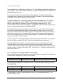
2 ACCESSOIRES
2.1 STX Cassettes
The StoreX can handle almost every plate currently available in the market. For
optimum performance Liconic offers a variety of cassettes. Beside the standard size
cassettes customized sizes are available on request.
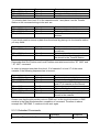
The table below lists the standard size cassettes. These sizes are stock items.
Cassette
Levels
Pitch
MTP (Micro Titer Plate)
Deepwell
NTP (Nano Titer Plate)
22
9
42
18
25
23
50
11
28
17
1536 Plate
LiCONiC
Standard Plate
Evotec NTP
D:\Products\STX\Stx40\STX_UE\Stx_ue05.doc
8/8
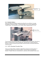
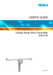
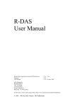
2.2 STX Transferstations
2.2.1 Standard Transferstation
A variety of transfer stations are available. The transfer station is accessed by the
StoreX handler as well as by any external robot. StoreX transfer stations will allow
most grippers access to the plate. All StoreX transfer stations are equipped with
alignment pins that will realign plates in both horizontal directions. The alignment is
works for the StroeX handling as well as for any external robotic transportation system.
Alignment Pins
Transfer
Plate
Attachment
Screws
Vertical
Ajustment Screw
The transfer station can easy be adjusted. The transfer plate can be adjusted
horizontally and vertically. Rotation of the transfer plate can also be adjusted.
The presence of a plate on the transfer station can be checked through the plate
sensor. The plate sensor status can be requested through the handling communication
port.
Plate Sensor
Plate Station
Connector
Plate Station
Holder
LiCONiC
D:\Products\STX\Stx40\STX_UE\Stx_ue05.doc
9/9
2.2.2 Turn Station
The StroeX handler transports plates along their longer axis. Many systems require
the plate to be presented rotated by 90 degree. The Turn Station will rotate each plate
before and after the access by the StoreX handler.
Plate Rotation
Drive
Rotation controlled by the StoreX system. No additional external software is required.
2.2.3 Swap Station
The Swap station has two transfer plates mounted on a rotation (swap-) drive. The
swap drive rotated the two transfer plates by 180 degree. The swap station acts as a
plate buffer as well as a plate extension shuttle. The distance of the actual transfer
position is increased by 145 mm.
The swap station is controlled by the user system. The swap station is accessed
through the handling communication port. The StoreX system will monitor possible
conflicts with the StroeX handler and the Swap Station.
The swap station has two plate sensors integrated. Both sensor status con be
requested individually.
LiCONiC
D:\Products\STX\Stx40\STX_UE\Stx_ue05.doc
10/10
Swap Drive
2.3 Shuttle Station
When the distance of transfer location to the StoreX is not sufficient, it may be
extended by the Shuttle Station. The Shuttle Station has a linearly displaceable
Transfer Plate. The travel path of the Transfer Plate is approximately 170 mm.
Shuttle Drive
The movement of the Shuttle Station are controlled by the StoreX system. Each time a
plates is accessed by the StoreX handling the Transfer Plate is shifted toward the
StoreX unit. After the access by the StoreX the Plate Shuttle is extended towards the
external system.
2.3.1 MTP (Standard) Transfer Plate
There are Transfer Plates available for applications where the transfer position is
mechanically attached to the external system. Transfer Plates have alignment
features. Transfer Plates are manufactured in aluminum with anodized surface finish.
LiCONiC
D:\Products\STX\Stx40\STX_UE\Stx_ue05.doc
11/11
Alignment Pins
Transfer Plate
2.3.2 NTP (Nano Titer Plate) Transfer Plate
Transfer Plate for NTP (Nano Titer Plates) and other very high density plates.
Attachment Bores
This Transfer Plate is best suited for very high alignment accuracy and for very light
plates. This Transfer Plate can be equipped with Active Alignment for even higher
alignment needs.
2.3.3 Transfer Plate Sensor
A very sensitive optical sensor can be integrated in the StoreX Transfer Stations. The
Transfer Plate Sensor will detect all commonly used plates. Transparent, opaque,
white or black plates are detected. The miniaturized design of the sensor helps to keep
the Transfer Station flat. The Transfer Plate Sensor is connected to the StoreX
system. The sensor status can be requested through the handling communication port.
LiCONiC
D:\Products\STX\Stx40\STX_UE\Stx_ue05.doc
12/12
Transfer Station
Plate Sensor
2.3.4 Active Plate Alignment
For applications with extremely high alignment accuracy there is an Active Plate
Alignment available. The Active Plate Alignment is attached to the Transfer Plate.
Every time a plate is accessed by the external system, the Active Plate Alignment is
selected. The alignment takes approximately one second. The alignment accuracy is
better than 0.1 mm.
The Active Plate Alignment is controlled by the external system. The access is
performed through the handler communication port.
2.4 Bar Code Reader
LiCONiC
D:\Products\STX\Stx40\STX_UE\Stx_ue05.doc
13/13
2.5 Gas Options
2.5.1 RH-Option
2.5.2 CO2 Option
2.5.3 O2 Option
2.5.4 Nitrogen Option
2.6 UHS (Ultra High Speed) Option
Applications with very short access times. The access speed of the UHS handler is
almost doubled compared to standard High Speed handlers.
2.7 Scheduler
A independent Scheduler traces the location and duration of presence in the climate
chamber. The Scheduler is timed by the StoreX internal clock. Two operation modes
can be selected.
The Trace Mode monitors the time of presence of each plate at the time of the
unloading of the plate. The actual time can be read by the external system through the
handler communication port.
The Alarm Mode indicates plates that remained the specified time in the climate
chamber to the external system. The remain time of each plate can be set by time of
loading the plate.
2.8 Customized Color
Standard coating of the StroeX is RAL 7035
LiCONiC
D:\Products\STX\Stx40\STX_UE\Stx_ue05.doc
14/14
3 TRANSPORT AND INSTALLATION
For transportation of the StoreX unit remove cassettes form climate chamber and
secure the lift assembly in its turn-in position. Always use the original StoreX box for
transportation. Do not lift the unit at the front door or at the Gate-Assembly. Use forklift for dislocating the instrument.
CAUTION !
• The StoreX unit weights up to 100kg (200 lbs.). Use adequate equipment for
transportation and/or displacement of the instrument.
• Transport unit in upright position with cassettes removed form the climate
chamber.
• Do not use front door or Gate as handles.
When installing the instrument follow the described steps in the given order below.
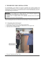
3.1 Unpacking the Instrument
•
•
•
Unpacking of the instrument is best done by two person
Remove fasten straps and open the cardboard box on the upper side
Open top cover of cardboard box
Cardboard box
•
Remove Cassettes and Foam Top
LiCONiC
D:\Products\STX\Stx40\STX_UE\Stx_ue05.doc
15/15
•
Lift the cardboard box over the instrument
Foam Top
Cassettes
Pallet
•
•
•
Lift the StoreX from the pallet base and carefully place it to the floor
Open the front door and remove the secure-wrapping from the lift assembly
Remove the Secure Tape and the Secure Wrapping which secure the Handler in
its home position
LiCONiC
D:\Products\STX\Stx40\STX_UE\Stx_ue05.doc
16/16
Secure Tape
Secure Wrapping
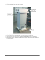
3.2 Installation of the Instrument
The instrument has to stand firmly on a flat and horizontal surface. Make sure that
there is no mechanical interference between the gate and any other equipment.
Adjust the four feet in their height until the instrument is horizontal and the desired
height. Use metric spanner size 12 for adjustment and size 17 to secure. Clockwise
turns of the Adjustment Screw will increase the height of the instrument.
Lockscrew
Adjustment
Check that each foot has contact with the ground and the instruments weight is evenly
distributed over all feet. Allow sufficient room between surface and ground floor. Check
rear side of the instrument for free Gate movement.
For optimum room usage you may stack several StoreX units. Allow approximately
10..20 mm clearance between units. The minimum clearance to the ground should be
greater than 30 mm. StoreX Cooling unit have their air inlet in the bottom surface.
Therefor the StoreX unit should only be operated in clean environment. Consult
maintenance guide for cleaning instruction.
LiCONiC
D:\Products\STX\Stx40\STX_UE\Stx_ue05.doc
17/17
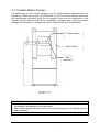
The air outlet is located at the front panel. The front panel must not be blocked by any
obstacle. Allow free air circulation.
Allow ~10mm clearance between units
Front Door
Front Panel
Ventilation Slits
Allow min. 30mm clearance to ground
For instruments with cooling option do not operate instrument immediately after
transportation. Leave instrument turned off for at least 12 hours.
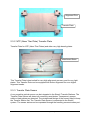
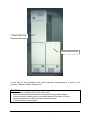
The picture below shows another possibility of arranging StoreX units. This example
depicts the combination of two Stand Alone units and one Table Top unit. This
arrangement allows maximum usage of valuable laboratory space. For easy
integration and short access paths the Gate of Table Top units is located near the
bottom of the unit while the Gate of Stand Alone units are located near the top of the
instrument.
LiCONiC
D:\Products\STX\Stx40\STX_UE\Stx_ue05.doc
18/18
StoreX Table Top
StoreX Stand Alone
A rear view of the instrument with some important measurements is given in the
charpter “Transfer Station Adjustment “.
CAUTION !
• Never cover ventilation slits of the instrument
• Allow minimum clearance between instrument and ground of 30mm
• Instruments with cooling option must settle power-off at least 12 hours
• Operate instrument in clean and dry environment only
• Consult Cleaning Instructions
LiCONiC
D:\Products\STX\Stx40\STX_UE\Stx_ue05.doc
19/19
3.3 Transfer Station Position
For adjustment of the transfer position use the utility software delivered with the
StoreX unit. Start the program „STXFER.EXE“ on the STX Utility Diskette and follow
the step-by-step procedure given by the program. Note that the adjustment of the
transfer position requires good skill in mechanics. Improper action may harm and/or
damage the instrument. If needed call Liconic Customer Service for assistance.
Transfer Station
Secure Holes
Gate
CAUTION !
• There is potential risk of injury by the Gate. Make sure that the Gate cannot be
accessed by the operator during operation
• When setting up the instrument, be sure to leave enough room on the rear side for
gate movement
•
LiCONiC
D:\Products\STX\Stx40\STX_UE\Stx_ue05.doc
20/20
Operate the instrument in dry and clean environment only. Note that external climate
situations may influence the performance of the instrument.
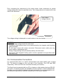
3.4 Installation and Removal of StoreX Handling
The StoreX Handling can be removed from the climate chamber for cleaning and
servicing purpose. The removal / installation procedure includes
•
•
•
•
•
•
Removing Cassettes from Climate Chamber
Securing Lift
Removing three handling attachment screws
Removing Handling Plug at inner side of Climate Chamber
Removing of two temperature sensors at the rear side if the Lift Tower
Carefully removing handling form Climate Chamber
For re-installation of the handling follow the steps above in reversed order.
Beware, after removing the handling form the Climate Chamber, the Handling has to
be re-aligned. Great care must be taken that all moving parts move freely and no cable
and other moving part of the Lift Assembly will interfere with any obstacle. Note that
above procedure requires good skill in mechanics. Improper operation may harm
and/or damage the instrument. Please call Liconic Customer Service for additional
information or customer training.
CAUTION !
• Though the entire StoreX handling can be removed for cleaning and servicing it is
recommended to call service for assistance.
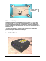
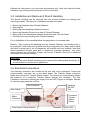
3.5 Electrical Connections
The electrical connection are located on the rear side of the instrument. Power and
communication connector are on the same panel. The Transfer Station connector
feeds and controls the Transfer Station Option. The StoreX unit automatically detects
the presence of a motorized Transfer Station through this connector. The Gas
Connector connects to optional gas supply such as CO2, Oxygen or Nitrogen. Beware
of maximum gas pressures of 6 bar.
Gas Connector
Main Switch
Connector
Transfer
Station
Option
Mains
Connector
Fuse Holder Voltage Selector
LiCONiC
Handling
RS-232
Port
D:\Products\STX\Stx40\STX_UE\Stx_ue05.doc
Options Port
21/21
Prior connecting the instrument to the mains power check instrument for proper
voltage setting and fuses for specified value. The voltage selector is located at the rear
side of the instrument.
Fuse Holder /
Voltage Selector
Backplane
The voltage setting is displayed in a small window in the fuse holder.
CAUTION !
• Beware of high voltage inside the instrument.
• Emergency stop functions have to be implemented by the integrator and his global
safety concepts.
• Do not open covers with mains connected. Disconnect mains cable prior any
service and/or maintenance work.
• Wrong voltage settings will permanently destroy the instrument.
• Instruments with integrated cooling option must be operated at the specified mains
frequency only.
3.6 Communication Connections
For communication there is a serial communication port (9pin Sub-D male, crossed
RX, TX) which is located on the rear side of the incubator. The RTS and DSR,
respectively DCD and DTR are connected internally (null modem).
The StroeX can be operated with any PC or Laptop or other system having a RS-232
port option. Terminal programs are available for most systems. A demo software that
includes a terminal option is shipped with each instrument. It is recommended to use
this software to get familiar with the command set of the StoreX system.
LiCONiC
D:\Products\STX\Stx40\STX_UE\Stx_ue05.doc
22/22
LiCONiC
D:\Products\STX\Stx40\STX_UE\Stx_ue05.doc
23/23
Handshake-lines are short-circuit internally.
LiCONiC
D:\Products\STX\Stx40\STX_UE\Stx_ue05.doc
24/24
4 MANUAL OPERATION
4.1 Front Door
The Front Door may be opened at the left side of the instrument. A Magnetic Sealing
keeps the Front Door closed. The Front Door should be kept closed all times. When
access is necessary, the Front Door should be opened for a short time only.
In order to avoid condensation an allow even temperature distribution inside the
instrument, the Front Door is heated. Note that extended times at opened Front Door
will also influence its temperature.
Pull right edge of Front Door
Front Shield
Magnetic Sealing
Front Door
The Front Door is opened by pulling the left edge of the Front Door. The Front Door
may be opened by an angle of almost 180 degree when standing alone. When placed
next to another StoreX unit the Front Door may be opened by approximately 100
degree.
Regularly inspect sealing performance of the Front Door. The Magnetic Sealing must
keep the Front Door firmly closed over its hole surface. When the Front Door is tilted
against the Front Shield it must be re-aligned by authorized service. Note that gaps
between Magnetic Sealing and Front Shield will cause undesired air exchange and
therefore condensation and degrade temperature distribution.
CAUTION !
• Use right edge of Front Door to open Front Door
• Keep Front Door closed at times of no access
LiCONiC
D:\Products\STX\Stx40\STX_UE\Stx_ue05.doc
25/25
• Make Front Door Access as short as possible
• Magnetic Sealing of Front Door must firmly close Front Door
• Keep Magnetic Sealing clean
4.2 Glass Door
Behind the Front Door there is the Glass Door. The Glass Door allows inspection of
the stored goods and observation of the function of the Handling while keeping the
climate stable.
The Glass Door may be opened at its left side. Keep the Glass Door closed at all
times. When access is necessary, the Glass Door should be opened as shortly as
possible. A Glass Door Access will dramatically influence climate inside the
instrument. Mainly humidity and CO2 is extremely sensitive to these accesses.
The Glass Door is sealed by the Inner Sealing. The Inner Sealing completely isolates
the Climate inside the Climate Chamber form the ambient climate. Gas exchange
between Climate Chamber and the exterior is almost eliminated.
Inner Sealing
Glass Door Lock
Glass Door Knob
When a Glass Door Access exceeds a certain time an alarm will occur. This alarm will
also prevent the Glass Door being left open unintended. The alarm may be stopped.
The alarm is re-trigged by closing the Glass Door.
CAUTION !
• Rotate Glass Door Knob clockwise to open Glass Door
• Keep Glass Door closed all time during critical processes. Opening the Glass Door
will dramatically change climate in Climate Chamber and destroy substances
• Make Front Door Access as short as possible
• Regularly inspect Glass Door Sealing
• Glass Door Lock must firmly close the Glass Door
LiCONiC
D:\Products\STX\Stx40\STX_UE\Stx_ue05.doc
26/26
• Keep Inner Sealing clean
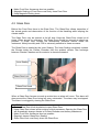
4.3 Cassettes
Cassettes allow simple and comfortable loading and unloading of storage goods.
Further cassette allow preparation outside the climate chamber. Once prepared the
goods can be quickly transferred into the climate chamber inside the StoreX unit.
The cassettes are open at their front side. On the back side there is the cassette back.
The plates are loaded from the front side.
Cassette
Sidewall
Plastic Rail
Plate (MTP)
To put a plate in the cassette center the plate to the desired level and slide the plate
towards the back of the cassette. Slightly lift the front of the plate to avoid excessive
wear of the retaining nozzles at the front end of the rails. When all plates are loaded
make sure that all plates are pushed towards the back of the cassette. Make sure that
all plates are pushed to the back of the cassette. Plates that jut out the front side of the
cassette may cause collision with the handler and may result damage to the handler.
Cassette must be treated with great care. Cassettes are aligned within 1mm when
leaving the factory. Miss-aligned, tilted or bent cassettes are frequent cause for
handling failures. Miss-aligned cassettes must be returned for re-alignment. Special
care must be taken when cassettes are filled with full plate load.
The cassette plate must be kept clean. Particles may cause the cassette to be tilted.
Do not place cassettes on the floor for they mey pick-up particles. Always store
cassettes inside the climate chamber or on clean surfaces.
Use cassette handle for transport. When lifting the cassette at its handle it will slightly
tilt backward in order to prevent plates from shifting to the front.
LiCONiC
D:\Products\STX\Stx40\STX_UE\Stx_ue05.doc
27/27
Cassette Handle
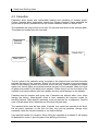
Never apply force to the cassettes. Do not drop cassettes. Mechanical shock will missalign the cassette. Never lift cassette at its side walls for this may bent the side walls of
the cassette. Bent side walls will cause the plates to block when being loaded and/or
unloaded.
Cassette Side Wall
In the rear event of a blockage of the extended shovel in the cassette, special care
must be taken when removing a cassette. In this case gently push the shovel
backwards until the shovel can move freely then remove cassette.
LiCONiC
D:\Products\STX\Stx40\STX_UE\Stx_ue05.doc
28/28
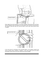
Cassette Handle
Cassette
Cassette Back
Cassette
Plate
The cassettes are secured by alignment rails to the cassette plate. The cassettes may
slightly be tilted backwards (towards the front opening) for removal. In order to load a
cassette align the back of then cassette base plate to the centering pins located on the
cassette plate. Push the cassette forward until it stands vertically. The cassette should
now firmly stand on the cassette plate. There should be no play present.
Centering Pins
Cassette Base Plate
Cassette Plate
Cassette Alignment Rail
LiCONiC
D:\Products\STX\Stx40\STX_UE\Stx_ue05.doc
29/29
To remove cassette slightly pull the cassette handle backward in order to tilt the
cassette. Lift the cassette until it becomes lose from the cassette alignment rail. Use
both hands for this operation. Never use force.
CAUTION !
• Make sure that ALL plates are pushed to the back of the cassette. Plates jut out
the front side of the cassette may cause collision with the handler shovel.
• Lift cassette at the cassette handle only
• Do not drop cassettes. Miss-aligned cassettes can cause handling errors
• Do not autoclave cassettes. Use disinfecting solution for sterilization.
• Keep cassette plate clean. Particles may tilt cassettes
4.4 The Robot Gate
The Robot Gate is located at the rear side if the instrument. Through the Robot Gate
the storage good is transported by the Handler. The Robot Gate is sealed like the
Front Door. Because of frequent accesses through the Gate special care must be
taken on the sealing performance of the Gate.
The Gate may make spontaneous movements. External commands, manual
interaction and internal protection time-out functions may cause the Gate to close.
Special care must be taken that the Gate cannot be accessed during operation.
The Gate movement is speed- and force controlled. However, the high demands on
the sealing capability of the Gate require certain minimum forces. The Gate can cause
painful interactions.
Never put hands into Gate opening when instrument is active..
4.5 Incubation Liquid
Di water , HC, IC not HC
2l capacity do not overfill
beware water front panel
LiCONiC
D:\Products\STX\Stx40\STX_UE\Stx_ue05.doc
30/30
Level-indicator
Poor over front cover
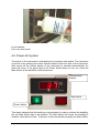
4.6 Power-On System
The power of the instrument is activated by the incubator main switch. The instrument
is turned on by pressing the power switch located at the front side of the instrument.
After power-on the climate portion of the instrument is activated automatically. An
alarm will occur. If the green light of the Power Switch does not turn on, check the
Main Switch at the back side of the instrument.
Themperature
Display
Start Switch
Power Switch
This alarm indicates that the handling is not activated. In order to activate the handling,
the red Start Switch has to be pressed. The Start Switch will cause the handling to
initialize. Note that the Gate - if opened- is also closed after pressing the Start Switch.
LiCONiC
D:\Products\STX\Stx40\STX_UE\Stx_ue05.doc
31/31
Pressing the Start Switch is equal to sneding an external Activate Command through
the Communication Port.
It is normal that some condensation occurs during warm-up. This condensation will
disappear once the internal climate is stabilized. The settling time may take several
hours.
The temperature inside the Climate Chamber is displayed on the Temperature
Display. The Temperature Display may not be used to set Temperature. The
Operating Temperature can only be set through the Communication Port.
4.7 Alarm System
Reset, Start, unauthorized access, Handler blockage
Close Gate
Alarm Sound Gate, Front Door, Not Init, Access Collition, Handler Blockage
4.8 Temperature Settings
Prior Startup of the instrument, the temperature of the instrument has to be set. Do not
set temperature higher than 45C. Higher temperatures may damage the handling
drives. For incubator temperature adjustment procedure consult the remote
communication chapter of this manual.
WARNING!
• Avoid incubator temperatures above 45C.
• Adjust temperature prior first startup.
The manual access is limited to the positioning of the carrousel. The Robot Gate
cannot be activated manually.
WARNING
• Remote Accesses have priority over manual accesses.
• The integrator has to make sure that no remote access is initiated during a manual
access (Always check Ready Bit prior sending command)
For manual positioning rotate the Positioning Key located in the front panel of the
incubator to a position 1..9. In order to accept a manual positioning, the key-switch
next to the positioning switch has to be put in its right position.
WARNING
• The Gate cannot be opened manually. Do not apply force to Gate.
4.9 Defrost
LiCONiC
D:\Products\STX\Stx40\STX_UE\Stx_ue05.doc
32/32
LiCONiC
D:\Products\STX\Stx40\STX_UE\Stx_ue05.doc
33/33
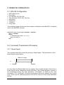
5 REMOTE OPERATION
5.1 RS 232 Configuration
•
•
•
•
•
•
•
•
ASCII data format
Full duplex
PC: Delimiter CR (Chr 13h)
PLC: Delimiter CR,LF (Chr 13h,10h)
9600 Baud
8 Data bits
1 Stop bit
Parity even
The example program shows how the comport is initialized under MS-DOS. For details
refer to the MS-DOS manuals.
FUNCTION STX_InitCom(pN:INTEGER):INTEGER;
VAR n:INTEGER;
BEGIN
n:=ModeCom(pN,9600,'E',8,1);
STX_InitCom:=n
END;
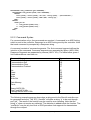
5.2 Command Transmission Procedure
5.2.1 Break Signal
The controller serial port is reset by sending a ‘Brake Signal’. The specification of the
Brake Signal is given below.
100ms or longer
V+
V-
In most cases the Brake Signal can be omitted. The example program shows how a
Brake Signal can be implemented under MS-DOS. The example program consists of
two procedures where the inner procedure “LCR_Brake” is called by the outer
procedure (“STX_ComReset”). Note that this program will directly address the comport
chip. There may be operating systems that will not allow the chip being addressed
directly.
LiCONiC
D:\Products\STX\Stx40\STX_UE\Stx_ue05.doc
34/34
PROCEDURE STX_ComReset(pN:INTEGER);
PROCEDURE LCR_Brake(rAdr,tme:INTEGER);
BEGIN
Port[rAdr]:=Port[rAdr] OR $40; Delay(tme); {Bit6=Brake }
Port[rAdr]:=Port[rAdr] AND $BF; Delay(2);
END;
BEGIN
CASE pN OF
1: LCR_Brake($3FB,500);
2: LCR_Brake($2FB,500);
END
END;
5.2.2 Command Syntax
For communication only a few commands are required. A command is an ASCII-string
which is sent to the controller. Response is an ASCII string sent by the controller. Note
that each command is prompted by a Response string.
A command consists of command segments. The first command segment defines the
intention of the command. Command segments are separated by Space (ASCII 20h).
Response Segments are separated by comma (ASCII 1Ch). The table below gives a
list of abbreviations used later on.
Command Segment
Communication Request
Communication Quit
Communication Clear
Communication Finished
Mnemonics
CR
CQ
CC
CF
Set
Reset
Read
Write
Write Set
ST
RS
RD
WR
WS
Data Memory
Timer
DM
T
Space ASCII 20h
Line Feed ASCII 0Ah
Carriage Return ASCII 0Dh
sp
lf
cr
The following example program shows how a string sent to the StoreX controller can
be generated and sent. The “STX_SendStr” will allow a string “s” to be sent through
port “pN”. The result of the function may be used for error handling. Note that the
string “s” does not require any delimiter. The delimiter is added inside the function. The
“auxStrAut” may be any low level or DOS procedure that supports the transmission
through the comport.
LiCONiC
D:\Products\STX\Stx40\STX_UE\Stx_ue05.doc
35/35
FUNCTION STX_SendStr(pN:INTEGER; s:STRING):INTEGER;
VAR ss:STRING;
BEGIN
STX_SendStr:=0;
ss:=Concat(s,cr);
auxStrOut(pN,ss)
END;
Since every command is prompted by the StoreX it makes sense to introduce a
procedure that handles this send-receive sequence. A possible solution is given below.
FUNCTION STX_ReadBackStr(pN:INTEGER; s:STRING):STRING;
CONST tries=2;
VAR i,n,m,err:INTEGER; w:WORD; s0,s1:STRING; c,kp:CHAR;
BEGIN
IF NOT(kbdEsc) THEN
BEGIN
EmptyAux(pN);
i:=-1;
s0:=s;
m:=Pos('-',s0);
IF m>0 THEN
BEGIN
Delete(s0,m,1);
s1:=Copy(s0,m,Length(s0));
Val(s1,n,err);
Delete(s0,m,Length(s0));
w:=-n; Str(w,s1); s0:=s0+s1
END;
REPEAT
Inc(i);
EmptyAux(pN); auxStrOut(pN,s0+cr);
IF i>3 THEN DelayMs(100);
auxStrIn(pN,s1,5,lf);
Delete(s1,PRED(Length(s1)),2)
UNTIL (s1[1]<>'E') OR (i>tries) OR KbdEsc;
STX_ReadBackStr:=s1;
END
ELSE
STX_ReadBackStr:=''
END;
5.2.3 Open / Close Communication
Prior communication with the controller, the communication has to be opened. Before
the communication is opened, the controller accepts only the Open Communication
Command (CR). For better safety, it is recommended to close communication (CQ)
when no communication is required for a longer period of time.
Open Communication
LiCONiC
Command
CR cr
D:\Products\STX\Stx40\STX_UE\Stx_ue05.doc
Response
CC cr lf
36/36
Send Commands (see below)
Close Communication
CQ cr
CF cr lf
The two example programs show how to open and close communication to the
StoreX.
FUNCTION STX_OpenCom(pN:INTEGER):STRING;
BEGIN
STX_OpenCom:=STX_ReadBackStr(pN,'CR')
END;
Time out functions and communication error can be trapped at this level.
FUNCTION STX_CloseCom(pN:INTEGER):STRING;
BEGIN
STX_CloseCom:=STX_ReadBackStr(pN,'CQ')
END;
These examples show how simple communication becomes when using the
“STX_ReadBack” procedure. The following example explain how often used
sequences are programmed. The ‘Set-‘procedure sets an internal relay (or flag). The
value of the flag becomes ‘1’. The ‘Reset-‘procedure resets an internal relay (or flag) .
The calue of the flag becomes ‘0’. Flags can be set, reset or read.
FUNCTION STX_Set(pN,rel:INTEGER):STRING;
VAR sR:STRING;
BEGIN
Str(rel,sR);
STX_Set:=STX_ReadBackStr(pN,'ST '+sR)
END;
FUNCTION KV_Reset(pN,rel:INTEGER):STRING;
VAR sR:STRING;
BEGIN
Str(rel,sR);
STX_Reset:=STX_ReadBackStr(pN,'RS '+sR)
END;
FUNCTION STX_Read(pN,rel:INTEGER):STRING;
VAR sR:STRING;
BEGIN
Str(rel,sR);
STX_Read:=STX_ReadBackStr(pN,'RD '+ sR)
END;
The Set and Reset will return an ‘OK’-response if operation is successful. The Readprocedure will return a ‘0’ or ‘1’.
Datamemories are 16 bit oriented. They can be read or written. The following
examples show how to use the datamemories.
FUNCTION STX_ReadDataMemory(pN,nbr:INTEGER):STRING;
LiCONiC
D:\Products\STX\Stx40\STX_UE\Stx_ue05.doc
37/37
VAR sR:STRING;
BEGIN
Str(nbr,sR);
STX_ReadDataMemory:=STX_ReadBackStr(pN,'RD DM'+ sR)
END;
FUNCTION STX_WriteDataMemory(pN,nbr:INTEGER; valu:WORD):STRING;
VAR sR,sV:STRING;
BEGIN
Str(nbr,sR); Str(valu,sV);
STX_ReadDataMemory:=STX_ReadBackStr(pN,'WR DM'+ sR + ' ' + sV)
END;
Not that the Response on above Write procedure is always ‘OK’. The Read procedure
will return a five-character-string.
5.2.4 Controller Error Messages
The following Error Codes are sent by the PLC. These error codes indicate systemerrors and are not the same as the Instrument own error-messages (refer to “Handling
Error Messages”)
Error
Relay Error
Comment
Undefined timer, counter, data memory,
check if requested unit is valid
Command Error
Invalid Command, check if communication is
opened by CR, check command sent to
controller, check for interrupts during string
transmission
Program Error
Firmware lost, reprogram controller
Hardware Error
Controller hardware error, turn controller
ON/OFF, controller is faulty and has to be
replaced
Write Protected Error Unauthorized Access
Base Unit Error
Unauthorized Access
Response
E0 cr lf
E1 cr lf
E2 cr lf
E3 cr lf
E4 cr lf
E5 cr lf
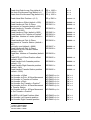
5.2.5 System Status
The Handling responds on Ready-Polling (“x”) is ‘0’ (handling not ready to accept
commands) or ‘1’ (handling ready, command may be sent). In its idle status the
handling sets the Ready Bit to ‘1’.
Read Ready-Bit
Command
RD sp 1915 cr
Response
x cr lf
When polling the ready Bit after sending a command, wait at least 200ms before
requesting the Ready Status. We recommend to wait 100ms – 200ms between polling
sequences.
LiCONiC
D:\Products\STX\Stx40\STX_UE\Stx_ue05.doc
38/38
A sample program will explain the polling sequence in detail. Note that monitoring a
flag change either form ‘0’ to ‘1’ or form ‘1’ to ‘0’ may also me advisable.
PROCEDURE STX_WaitReady(portNbr:INTEGER);
BEGIN
DelayMs(300);
WHILE (STX_Read(portNbr,1915)='0') AND NOT(KeyPressed) DO
DelayMs(200)
END;
NOTE !
• Commands may only be sent when Ready Bit equal ‘1’ (RD 1915 -> ’1’).
• Allow >200ms delay between any command and the first Ready Bit request.
• Use 100ms..200ms delay between requests.
5.3 Commands
5.3.1 Basic Commands
Reset
LiCONiC
Command
ST sp 1900 cr
D:\Products\STX\Stx40\STX_UE\Stx_ue05.doc
Response
OK cr lf
39/39
Read Ready Flag
Read Error Flag
Read Plate-Ready Flag
RD sp 1915 cr
RD sp 1814 cr
RD sp 1914 cr
x cr lf
x cr lf
x cr lf
Activate Handling System
Deactivate Handling System
Read Status Handling System
ST sp 1801 cr
RS sp 1801 cr
RD sp 1801 cr
OK cr lf
OK cr lf
x cr lf
Set cassette slot position m (0..m)
Set Handler level position n (1..n)
Set Handler Cassette Pitch
WR sp DM0 sp m cr
WR sp DM5 sp n cr
WR sp DM23 sp p cr
OK cr lf
OK cr lf
OK cr lf
Open gate
ST sp 1901 cr
1) Close gate
ST sp 1902 cr
2) Continue Access (on Handshake Mode)
OK cr lf
OK cr lf
Terminate Access
Load plate to m,n*)
Unload plate from m,n*)
Set plate to x-fer station m,n*)
Get plate from x-fer station m,n*)
Pick plate form cassette, level m,n*)
Place plate to cassette, level m,n*)
Position z-Lift for BCR reading m,n*)
ST sp 1903 cr
ST sp 1904 cr
ST sp 1905 cr
ST sp 1906 cr
ST sp 1907 cr
ST sp 1908 cr
ST sp 1909 cr
ST sp 1910 cr
OK cr lf
OK cr lf
OK cr lf
OK cr lf
OK cr lf
OK cr lf
OK cr lf
OK cr lf
Activate Shovel Transfer Sensor (70º C HT
Version)
Rotate Swap Station 180 degr.
Rotate Swap Station back to home position
Read Shovel Plate Sensor
Read Transfer Station Plate Sensor
Read 2nd Transfer Station Sensor
Read Swap Station position
ST sp 1911 cr
OK cr lf
ST sp 1912 cr
RS sp 1912 cr
RD sp 1812 cr
RD sp 1813 cr
RD sp 1807 cr
RD sp 1912 cr
OK cr lf
OK cr lf
x cr lf
x cr lf
x cr lf
x cr lf
RD DM982 cr
ttttt cr lf
RD DM890 cr
sssss cr lf
Read Actual Temperature (1/10º
Celcius)
Read Set Temperature value (1/10º C; e.g.
370 = 37.0º Celcius)
Set operation temperature (1/10º C)
Read Actual Humidity (1/10% RH)
Read Set Temperature value (1/10% RH;
e.g. 900 = 90.0% RH)
Set operation temperature (1/10% RH)
Read Actual CO2 concentration (1/100%
CO2 Vol.)
Read Set CO2 value (1/10º C; e.g. 370 =
37.0º Celcius)
Set operation CO2 concentration
(1/100% CO2 Vol.)
Reponse ‘x’ expect ‘0’ or ‘1’.
WR DM890 sp ttttt cr OK cr lf
RD DM983 cr
ttttt cr lf
RD DM893 cr
sssss cr lf
WR DM893 sp ttttt cr OK cr lf
RD DM984 cr
ttttt cr lf
RD DM894 cr
sssss cr lf
WR DM894 sp ttttt cr OK cr lf
t = actual value (Word=16Bit)
LiCONiC
D:\Products\STX\Stx40\STX_UE\Stx_ue05.doc
40/40
s = set value (Word=16Bit)
The cassette slot is selected by sending m=1..2. The handler is positioned towards the
specified slot. Note that cassette levels are numbered starting at the bottom level
upwards. Bottom level is 1.
The Activate Handler-Command initializes the handling. Use the Activate Handler
Command after cold-start or after sending a Reset Command. The Activate Handler
Command should not be used as ‘on-off’ function.
Functions marked with *) can only be used with selected cassette slot. The value of
number of cassettes is stored in DM29. The value of number of levels is stored in
DM25. When using the Position z-Lift for BCR reading command the ST 1910
command has to send once only. Once set, the handler is positioned by simply writing
the carrousel and level position into DM0 and DM5.
The Activate Plate Sensor command is used in HT-units only. In HT units the Shovel
Plate Sensor is deactivated by default. Prior reading the sensor status it has to be
turned on by sending the Activate Plate Sensor command (ST 1911). This command
will turn the sensor on for ~2 seconds. The sensor can be read during this period of
time. After turning the sensor on wait approximately 0.1 seconds before reading the
sensor with the RD 1812 command.
The Error-Flag is set when the handling cannot finish a movement within time. Check
the Error-Flag by sending “RD 1814” when the Ready-Bit does not become ‘1’.
The Plate Ready flag (1815) is set when the system has cleared the plate from the
Transfer Station on executing a Load command or when a plate is placed on the
Transfer Station during an UnLoad command. This Plate Ready flag allows increased
access speeds. The read Plate Ready (RD 1815) returns '1' until the read Ready flag
(RD 1915) is set to '1'.
5.3.2 Examples of Usage of Basic Commands
The following example strings show the usage of the basic commands. To Initialize the
system after a cold-start or a reset you may send:
Command
ST sp 1801 cr
Response
OK cr lf
Comment
Initialize Command
Prior sending a initialization command you may request the system status by reading
the Ready Flag:
Command
RD sp 1915 cr
RD sp 1915 cr
Response
'1' cr lf
'0' cr lf
Comment
System Ready
System Busy
To load a plate from the Transfer Station to level 10 in the cassette at slot 2. The
command to be sent is:
LiCONiC
D:\Products\STX\Stx40\STX_UE\Stx_ue05.doc
41/41
Command
WR sp DM0 sp 2 cr
WR sp DM5 sp 10 cr
ST sp 1904 cr
Response
OK cr lf
OK cr lf
OK cr lf
Comment
Position rotation at slot 2
Select level 10 in cassette
Load Command to start Load process
To unload a plate form level 22 in the cassette at slot 1 and place it on the Transfer
Station to the command strings to be sent are:
Command
WR sp DM0 sp 1 cr
WR sp DM5 sp 22 cr
ST sp 1905 cr
Response
OK cr lf
OK cr lf
OK cr lf
Comment
Position rotation at slot 1
Select level 22 in cassette
Unload Command to start Load
process
If you simply want to remove a plate from the shovel by placing it to the transfer station
you may send:
Command
WR sp DM0 sp 1 cr
Response
OK cr lf
WR sp DM5 sp 1 cr
ST sp 1906 cr
OK cr lf
OK cr lf
Comment
Position rotation at any position; must
be defined
Select any level
Start execution of setting plate from
the shovel to the Transfer Station
Remember that Slot Position and Level Position must also be set at the "ST 1906" and
" ST 1907" command.
In order to transport one plate from level 15 of cassette 2 to level 17 of the same
cassette 2 the following sequence has to be sent:
Command
WR sp DM0 sp 2 cr
WR sp DM5 sp 17 cr
ST sp 1908 cr
Response
OK cr lf
OK cr lf
OK cr lf
RD sp 1915 cr
RD sp 1915 cr
WR sp DM5 sp 15 cr
ST sp 1909 cr
'0' cr lf
'0' cr lf
OK cr lf
OK cr lf
Comment
Position rotation at slot 1
Pick plate from level 17 of cassette 2
Start execution of Pick plate from
level 17 of cassette on the Shovel
System busy executing command
System Ready for next command
Select level 15
Place command to place plate form
shovel to the cassette
Please note that the slot position value in DM0 and / or the level information in DM5
remains in the Data Memories after completion of command. Therefore in above
example the "WR DM0 1" needs not to be sent again.
5.3.3 Extended Commands
Read Error Flag (default =0)
LiCONiC
Command
RD sp 1814 cr
D:\Products\STX\Stx40\STX_UE\Stx_ue05.doc
Response
x cr lf
42/42
Read Auto-End-Access Flag (default =1) RD sp 1600 cr
Set Auto-End-Access Flag (default =1)
ST sp 1600 cr
Reset Auto-End-Access Flag (default =1) RS sp 1600 cr
x cr lf
x cr lf
x cr lf
Read Actual Slot Position n (0..2)
RD sp DM1 cr
nnnnn cr lf
Read Handler z-Offset (default = 600)
Read Handler dz Pick- & PlaceMovement in Cassette (default = 500)
Read Handler In-Transfer z-Position
(default ~42’000)
Read Handler z-Pitch (default =1925)
Read Handler Out-Transfer z-Position1
Read Max. Number of Levels (default =
22)
Read Handler dz Pick- & PlaceMovement at Transfer Station (default =
800)
Internally used (default = 9999)
Read Handler dz Pick- & PlaceMovement at Out-Transfer Station
(default = 800)2
Read Max. Number of Cassettes (default
= 2)
Read BCR z-Lift Read Position offset
(default ~200)
Read Handler Left Cassette position
(default ~70)
Read Handler Right Cassette position
(default ~940)
Read Handler Transfer Station position
(default ~3500)
RD DM20 cr
RD DM21 cr
ddddd cr lf
ddddd cr lf
RD DM22 cr
ddddd cr lf
RD DM23 cr
RD DM24 cr
RD DM25 cr
ddddd cr lf
ddddd cr lf
ddddd cr lf
RD DM26 cr
ddddd cr lf
RD DM27 cr
RD DM28 cr
ddddd cr lf
ddddd cr lf
RD DM29 cr
RD DM62 cr
ddddd cr lf
RD DM80 cr
ddddd cr lf
RD DM81 cr
ddddd cr lf
RD DM82 cr
ddddd cr lf
Set Handler z-Offset
Set Handler dz Pick- & Palce-Movement
Set Handler In-Transfer z-Position
Set Handler z-Pitch
Set Handler Out-Transfer z-Position3
Set Handler dz Pick- & Place-Movement
at Transfer Station
Set Handler dz Pick- & Place Movement
at Out-Transfer z-Position4
WR DM20 sp d cr
WR DM21 sp d cr
WR DM22 sp d cr
WR DM23 sp d cr
WR DM24 sp d cr
WR DM26 sp d cr
OK cr lf
OK cr lf
OK cr lf
OK cr lf
OK cr lf
OK cr lf
WR DM28 sp d cr
OK cr lf
Set BCR z-Lift Read Position offset
Set Handler Left Cassette position
Set Handler Right Cassette position
WR DM62 sp d cr
WR DM80 sp d cr
WR DM81 sp d cr
OK cr lf
OK cr lf
OK cr lf
1
Handler: DM24 = DM22
Handler: DM26=DM28
3
StoreX: DM24 = DM22
4
StoreX: DM26 = DM28
2
LiCONiC
D:\Products\STX\Stx40\STX_UE\Stx_ue05.doc
43/43
Set Handler Transfer Station position
WR DM82 sp d cr
OK cr lf
d = data (Word=16Bit)
x = 0,1 (Word=16Bit)
t = actual value (Word=16Bit)
s = set value (Word=16Bit)
5.3.4 Short Access Commands
The following commands allow extremely short and simple command sequences.
When using short commands the plates are numbered from 1 to the maximum plate
capacity. The maximum plate capacity is the value in DM25 (number of levels)
multiplied with the value in DM29 (number of cassettes). The way the plates are
numbered can be selected. By default the plates are numbered beginning at the
lowest level of cassette 1 to the top level of cassette 1, continuing at the lowest level of
cassette 2 ending at the top level of cassette 2 (Vertical Mode). The optional
numbering starts at the lowest level of cassette 1, lowest level of cassette 2, second
level of cassette 1, second level of cassette 2, third level of cassette 1 etc. (Horizontal
Mode).
Load plate n
UnLoad plate n
UnLoad plate n (unsigned alternative)
Command
WR sp DM10 sp n cr
WR sp DM10 sp -n cr
WR sp DM15 sp n cr
Select Vertical Numbering Mode (default) ST sp 1604 cr
Select Horizontal Numbering Mode
RS sp 1604 cr
Response
OK cr lf
OK cr lf
OK cr lf
OK cr lf
OK cr lf
One Short Access Command can be sent while the prior access is being executed.
This second command is stacked and executed after termination of the first command.
5.4 Handling Status / Error Messages
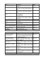
Error Commands are used when the handling detects an internal error (e.g. when
loading a plate to an occupied location). In case of error the Error Flag (1814) is set
from ‘0’ to ‘1’. The exact cause of an error can be found in the data memory 200
(DM200). For each type of error an error code is set in DM200. The list below shows
the meaning of the error code.
Errors are read by reading the content of DM200. On a time-out, first the Error Flag is
read (RD 1814). Then DM200 is read in order to find the cause of error. An error is
reset by sending the Reset Command (ST 1900).
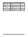
Errors DM200=1xx are Load Plate Errors, errors DM200=2xx are Unload Plate Errors.
Read Error Flag (default =0)
Read Error Code
Command
RD sp 1814 cr
RD sp DM200 cr
Response
x cr lf
x cr lf
The following tables will list the StoreX status messages.
LiCONiC
D:\Products\STX\Stx40\STX_UE\Stx_ue05.doc
44/44
Error
General Handling Error
Description
Handling action could not be performed
in time.
Gate could not reach upper position or
Gate did not reach upper position in
time
Gate could not reach lower position or
Gate did not reach lower position in
time
Handler-Lift could not reach desired
level position or
does not move
Unauthorized
user
access
in
combination with manual rotation of
carrousel
Cassette slot cannot be reached
Undefined cassette level has been
requested
Unload operation while plate is on
transfer station
Lift could not be initialized
Trying to load a plate, when a plate is
already on the shovel
Trying to remove or place plate with no
plate on the shovel
Recovery was not possible
Code
00001 cr lf
Description
Carousel could not reach desired radial
position during Load Plate procedure or
Lift could not reach transfer level during
Load Plate procedure.
Handler could not reach outer turn
Load Plate Handler
position at transfer level during Load
Transfer Turn out Error
Plate procedure.
Load Plate Shovel Transfer Shovel could not reach outer position at
transfer level during Load Plate
Outer Error
procedure.
Load Plate Lift Transfer
Lift did not reach upper pick position at
Error
transfer level during Load Plate
procedure.
Load Plate Shovel Transfer Shovel could not reach inner position at
Inner Error
transfer level during Load Plate
procedure.
Load Plate Handler
Handler could not reach inner turn
Transfer Turn in Error
position at transfer level during Load
Plate procedure.
Load Plate Lift Cassette
Lift could not reach desired cassette
Code
00100 cr lf
Gate Open Error
Gate Close Error
General Lift Positioning
Error
User Access Error
Cassette Slot Error
Remote Access Level
Error
Plate Transfer Detection
Error
Lift Initialization Error
Plate on Shovel Detection
No Plate on Shovel
Detection
No recovery
Error
Load Plate Cassette
Positioning Error
LiCONiC
D:\Products\STX\Stx40\STX_UE\Stx_ue05.doc
00007 cr lf
00008 cr lf
00009 cr lf
00010 cr lf
00011 cr lf
00012 cr lf
00013 cr lf
00014 cr lf
00015 cr lf
00016 cr lf
00017 cr lf
00101 cr lf
00102 cr lf
00103 cr lf
00104 cr lf
00105 cr lf
00106 cr lf
45/45
Travel Error
Load Plate Shovel
Cassette Front Error
level during Load Plate procedure.
Shovel could not reach front position on
cassette access during Plate Load
procedure.
Load Plate Lift Cassette
Lift could not reach cassette place level
Place Error
during Load Plate procedure.
Load Plate Shovel
Shovel could not reach inner position at
Cassette Inner Error
cassette plate placement during Load
Plate procedure.
Load Plate Lift Travel Back Lift could not reach zero level during
Error
Load Plate procedure.
Load Plate Lift Init Error
Lift could not be initialized after Load
Plate procedure.
LiCONiC
D:\Products\STX\Stx40\STX_UE\Stx_ue05.doc
00107 cr lf
00108 cr lf
00109 cr lf
00110 cr lf
00111 cr lf
46/46
Error
Unload Plate Lift Cassette
Travel Error
Unload Plate Shovel
Cassette Front Error
Unload Plate Lift Cassette
Load Error
Unload Plate Shovel
Cassette Inner Error
Unload Plate Lift Transfer
Positioning Error
Unload Plate Handler
Transfer Turn out Error
Unload Plate Shovel
Transfer Outer Error
Unload Plate Lift Transfer
Place Error
Unload Plate Shovel
Transfer Inner Error
Unload Plate Handler
Transfer Turn in Error
Unload Plate Lift Travel
Back Error
Unload Plate Lift Init Error
LiCONiC
Description
Carousel could not reach desired radial
position during Unload Plate procedure
or
Lift could not reach desired cassette
level during Unload Plate procedure.
Shovel could not reach front position on
cassette access during Plate Unload
procedure.
Lift could not reach cassette pick level
during Unload Plate procedure.
Shovel could not reach inner position at
cassette plate pick during Unload Plate
procedure.
Lift could not reach transfer level during
Unload Plate procedure.
Handler could not reach outer turn
position at transfer level during Unload
Plate procedure.
Shovel could not reach outer position at
transfer level during Unload Plate
procedure.
Lift did not reach lower place position at
transfer level during Unload Plate
procedure.
Shovel could not reach inner position at
transfer level during Unload Plate
procedure.
Handler could not reach inner turn
position at transfer level during Unload
Plate procedure.
Lift could not reach Zero position
during Unload Plate procedure.
Lift could not be initialized after Unload
Plate procedure.
D:\Products\STX\Stx40\STX_UE\Stx_ue05.doc
Code
00200 cr lf
00201 cr lf
00202 cr lf
00203 cr lf
00204 cr lf
00205 cr lf
00206 cr lf
00207 cr lf
00208 cr lf
00209 cr lf
00210 cr lf
00211 cr lf
47/47
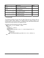
Error
Plate Remove Errors
(1906)
BarCode Read Errors
(1910)
Plate Place Errors (1909)
Plate Set Errors (1907)
Plate Get Errors (1908)
Description
Errors as above but in conjunction
Remove Plate Command
Errors as above but in conjunction
BCR Command
Errors as above but in conjunction
Place Plate Command
Errors as above but in conjunction
Set Plate Command
Errors as above but in conjunction
Get Plate Command
Code
with 003xx cr lf
with 004xx cr lf
with 005xx cr lf
with 006xx cr lf
with 007xx cr lf
d = data (Word=16Bit)
x = 0,1 (Word=16Bit)
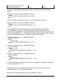
The following example will show how the ready Polling can be combined with the
continuos system status request. The program below will display details of the
handling actions of the StoreX handler. In combination with a data base detailed status
reports can be output real-time to the operator all time.
PROCEDURE STX_WaitReadyTrace(portNbr:INTEGER);
VAR c:CHAR; x,y,err:INTEGER; n:WORD;
BEGIN
WRITE(' ');
x:=WhereX; y:=WhereY;
DelayMs(300);
WHILE (STX_Read(prtNbr,1915)='0') AND NOT(KeyPressed) DO
BEGIN
DelayMs(100);
GotoXY(x,y);
Val(STX_ReadDataMemory(portNbr,200,n,err); WRITE(n:3)
END
END;
LiCONiC
D:\Products\STX\Stx40\STX_UE\Stx_ue05.doc
48/48
5.5 Program Examples
LiCONiC
D:\Products\STX\Stx40\STX_UE\Stx_ue05.doc
49/49
LiCONiC
D:\Products\STX\Stx40\STX_UE\Stx_ue05.doc
50/50
A universally usable procedure which can be used for most StoreX commands is given
below. Use this procedure after initializing the instrument only.
LiCONiC
D:\Products\STX\Stx40\STX_UE\Stx_ue05.doc
51/51
PROCEDURE STX_DoPlate(pN,slot,level:INTEGER; command:STRING);
BEGIN
IF NOT(KeyPressed) THEN
BEGIN
STX_WaitReady(pN);
STX_WriteDataMemory(pN,0,slot);
STX_WriteDataMemory(pN,5,level);
STX_Set(pN,command);
STX_WaitReadyTrace(portNbr)
END;
END;
LiCONiC
D:\Products\STX\Stx40\STX_UE\Stx_ue05.doc
52/52
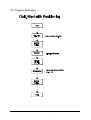
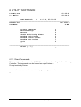
6 UTILITY SOFTWARE
LiCONiC R&D
C.G.Malin
01-06-96
09:04:01
HBI-UserSoft
*
V 0.04, 25.05.96
______________________________________________________________
Heraeus AG
HBI 2001-3
UserName
S-Nbr
Direct Commands
Monitor Flags
Macros
Teach Positioning Times
Random Positioning
Random Access Cycles
Random Fast Access
Quit
1
2
3
4
5
6
7
0
______________________________________________________________
Enter [0..7]
_
6.1.1 Direct Commands
Direct entering of commands (ASCII-Characters) and sending to the Handling
Controller. The commands can be entered as capital letters or
Prompt entries by Return.
Enter direct commands to KV-PLC, press q to quit
_
LiCONiC
D:\Products\STX\Stx40\STX_UE\Stx_ue05.doc
53/53
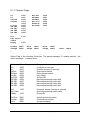
6.1.2 Monitor Flags
P0
Pn
GtClse
GtOpen
F.Door
SW 2E0
SW 2E1
SW 2E2
SW 2E3
0000
0001
0002
0003
0004
0005
0006
0007
0008
0009
Rot.EN
GateEN
GateEN
Rot.Dir
GtTmOut
AccsLED
0500
0501
0502
0503
0504
0505
Acs.
1100
Key Valid
InPos
Ready
1915
RotPos. DM01
SetSpd. DM91
_
Accs. DM00
aSlpe. DM92
AccV. DM02
bSlpe. DM93
intvl. DM94
Status Flag of the Handling Controller. The status message “0“ means inactive, the
status message “1“ means active.
Code
Status Flag
Comment
P0
Pn
GtClse
GtOpen
KeySw
Gn LED
SW 2E0
SW 2E1
SW 2E2
SW 2E3
0000
0001
0002
0003
0004
0005
0006
0007
0008
0009
0-initiator of carousel
Position-initiator of carousel
Gate closed switch
Gate opened switch
Key switch
Green LED
Manual positioning switch bit0
Manual positioning switch bit1
Manual positioning switch bit2
Manual positioning switch bit3
Acs.
1100
Key Valid
Ready
1915
Carousel access (remote or manual)
Manual positioning switch valid
Ready-Bit
Rot.Pos.
Access.
AccV.
Actual carrousel position
Carousel set position
Access accepted
LiCONiC
DM1
DM0
DM2
D:\Products\STX\Stx40\STX_UE\Stx_ue05.doc
54/54
6.1.3 Macros
Sending of complete, preprogrammed command sequences.
Function
Command
Key
Rot. Position
Enable Rotation
Gate Open
Gate Close
End Access
Shaker ON
Shaker OFF
CarAct ON
CarAct OFF
Command Reset
WR
WR
ST
ST
ST
ST
RS
ST
RS
ST
1..9
0
O
C
E
S
F
A
D
R
Quit
Ready [1915]
--
Please Select ->
_
DM0 x
DM0 0
1901
1902
1903
1907
1907
1801
1801
1900
esc
Code
Comment
0
1..9
No access, carrousel rotation enabled
Position carousel
O
C
R
Gate open (only when carousel is positioned)
Gate closed
Reset Handling Controller
Q
Exit macro menu
Accs.
Ready
Carousel access (remote or manual)
Ready-Bit
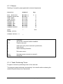
6.1.4 Teach Positioning Times
Program to measure positioning times of the carrousel.
The program starts positioning automatically. As a result a table containing the
measured positioning times is presented.
LiCONiC
D:\Products\STX\Stx40\STX_UE\Stx_ue05.doc
55/55
6.1.5 Random Positioning
Program for positioning the carousel randomly without gate movements.
After entering the access intervals the program continuously simulates accesses at
random positions until the “q-Key“ is pressed. As a result a table containing statistical
data is presented.
If an error of positioning time larger then 0.4 seconds compared with the calibrated
positioning time is observed a positioning error is assumed and monitored.
6.1.6 Random Access Cycles
Program for positioning the carousel randomly including gate movements.
After entering the access intervals the program continuously simulates accesses at
random positions until the “q-Key“ is pressed. As a result a table containing statistical
data is presented.
If an error of positioning time larger then 0.4 seconds compared with the calibrated
positioning time is observed a positioning error is assumed and monitored.
6.1.7 Random Fast Access
Program for positioning the carousel randomly including combined positioning-gate
movements commands.
After entering the access intervals the program continuously simulates accesses at
random positions until the “q-Key“ is pressed. As a result a table containing statistical
data is presented.
If an error of positioning time larger then 0.4 seconds compared with the calibrated
positioning time is observed a positioning error is assumed and monitored.
LiCONiC
D:\Products\STX\Stx40\STX_UE\Stx_ue05.doc
56/56
7 TROUBLESOOTING
The following list shows the possible errors of StoreX handler which can be removed
by a customer. If the steps below doesn’t give you the success, you need, please
contact an authorized service personnel.
CAUTION!
• Never touch electrical connectors as long the Handler is in connection with the
external net or one or more covers are removed.
• If there is some work with the lift assembly or inside the climate chamber always
disconnect mains.
Error
Cause
Action
Instrument does not power-up,
green light of the Power Switch
is off
Main Switch at the rear side of
the instrument is turned off
Fuse burned
Turn Main Switch on
Handler doesn’t react on
external commands
Some fault in the electrical
connectors/cables
Check handling RS232/V24
plug respectively 9pol. cable of
PC to Null-Modem
Built respectively control the
communication with single
orders.
Call service personnel
No communication to NullModem
Internal error
Handler doesn’t react at all
No connection
Fuse damage
Error in electrical connection
between Null-Modem and
external net
Belt is displaced
Internal error
LiCONiC
Replace Fuse(s)
Control Voltage setting and
ON/OFF switch
Control fuse and in case of
damage replace it (2AT)
Control connection respectively
25pol. exterial connector cable
null modem
Control belt for damage and put
it into right position again
Call service personnel
D:\Products\STX\Stx40\STX_UE\Stx_ue05.doc
57/57
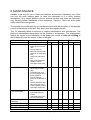
8 MAINTAINANCE
Handler 4 are only for use in clean and dustfree environment (laboratory use). Dust
can hurt the open rotating parts. In case the instrument is in a dusty unclean
atmosphere for a longer distance of time, remove the dust and clean the instrument
very carefully before installation of the instrument. Caution ! There are some parts
which need some new grease.
The handler 4 is constructed for no maintenance and with the exception of the periodly
control of the tension of the belt, they don’t need any regular service.
The lift assembly takes a minimum of regular maintenance and controlworks. The
period of maintenance dependence on the number of movements . The maintenance
means the control of the lubrication of the gears, the control of mark of oil-filling in
the lift assembly and the control of play in the gear.
Check
Lift assembly
•
•
•
•
•
•
Mo.
Lubrication film over the 2
entire length of the lift
rails
Free of particles
Must not indicate wear
Remove old lubrication
film
Apply new lubrication
film
Play of the vertical lift
guidance means
exchange of the parts
Maint.
Replace
Mov.
20000
Mo.
6
Mov.
Mo.
50000 --
Mov.
--
Shovel Guidance
• Control max. play in
height-play and sideplay
• Lubrication film over
the entire length of the
linear-guidance
• Free of particles
• Remove old lubrication
film
• Renew lubrication film
• Too much play in the
linear guidance means
exchange of the parts
2
20000
6
50000 --
--
Turn Drive Belt
• Check for wear
• Check belt teeth for
cracks
• Check belt metal core
for free metal parts
•
2
20000
6
50000 12
--
2
--
6
--
--
Climate Chamber
Cleaning
Condenser Cleaning •
•
Defrost
Front Door Sealing • Control the wear of the
LiCONiC
D:\Products\STX\Stx40\STX_UE\Stx_ue05.doc
12
58/58
Gate Sealing
Front Panel Sealing
Glass Door Sealing
belt
• The edge of the belt
may not indicate wear
• The fabric of the belt is
not visible
• Tighten the belt
•
•
• Control the wear of the 2
belt
• The edge of the belt
may not indicate wear
• The fabric of the belt is
not visible
--
6
--
12
--
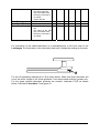
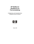
For lubrication of the radial-lead there is a lubrication-hole in the front side of the
Laufwagen. Put lubrication in the lubrication-hole until it floods the sealing on the side.
For the Lift assembly lubricate at A, B as sown below. Make sure that lubrication will
cover the entire length of the linear-guidance. Use recommend acid-free grease only.
For the gears special lubrication products are needed. Lubricate C,D,E as shown
below. Lubrication thoothbar F and gears G.
LiCONiC
D:\Products\STX\Stx40\STX_UE\Stx_ue05.doc
59/59
8.1 Cleaning
If there are some parts which are contaminated , you can clean them easily with
regular disinfecting-cleaner. Always remove old lubrication on external parts and
replace it with new lubrication film.
8.2 Tension
For the correct tension of the Turn Drive belt
LiCONiC
D:\Products\STX\Stx40\STX_UE\Stx_ue05.doc
60/60
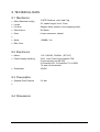
9 TECHNICAL DATA
9.1 Mechanics
• Slots (Standard config.)
2 MTP-Positions, max. load 5 kg
• Levels
22, usable height / level 17mm
• Lift drive
Stepper Motor, bipolar, micro-stepping mode
• Shovel drive
DC-Motor
• Gate
Linear movement, heated
•
• Noise
<52dBA / 1m
• RAL Color
9.2 Electronics
• Mains
115 / 230VAC, 50/60Hz (STX-IC)
• Power-Supply Handling
24V=, max. Power Consumption 70W,
Communication via RS-232
2=Controller RX, 3=Controller TX, 5=GND
7,8 and 4,6 shortended
• Gateheater
24VDC
9.3 Pneumatics
• Optional Gas Pressure
2.6 bar
•
9.4 Dimensions
LiCONiC
D:\Products\STX\Stx40\STX_UE\Stx_ue05.doc
61/61
LiCONiC
D:\Products\STX\Stx40\STX_UE\Stx_ue05.doc
62/62