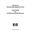
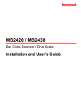
1
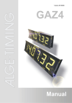
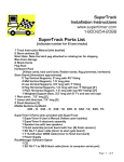
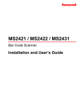
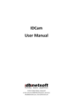
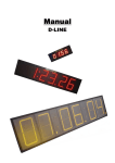
Version-E111206
Teledata
TED-TX10 and TED-RX10
Manual
Manual
TED-TX/RX10
Declaration of Conformity
We hereby declare that the following product complies with the below stated standards. All
components used by us are CE certified by their producer and are not modified by ALGETIMING GmbH.
ALGE-TIMING GmbH
Rotkreuzstrasse 39
A-6890 Lustenau
We,
declare in sole responsibility that the radio receiver
Teledata TED-RX10
complies with the following standards/normative documents and in case of intended use
complies with the basic requirements of R&TTE 1999/5/EC:
Telecommunication (TC)terminal device
Short Range Device
Applied harmonized standards…
EN 60950-1: 2006
EMC:
EN300220-1 1.3.1
2000-09
EN 300220-3 1.1.1 2000-09
EN 301489-1 V1.8.1 2008
EN 301489-3 V1.4.1 2002
EN55022:2006+A1:2007
EN55024:1998+A1:2001+A2:2003
EN61000 3-2:2006
EN61000 3-3:1995+A1:2001+A2:2005
Additional information:
The product complies with the low voltage directive 73/23/EEC and EMC directive
2004/108EG and carries the CE sign.
Lustenau, 12.01.2010
ALGE-TIMING GmbH
Albert Vetter
(CEO)
Page 2
Manual
TED-TX/RX10
Declaration of Conformity
We hereby declare that the following product complies with the below stated standards. All
components used by us are CE certified by their producer and are not modified by ALGETIMING GmbH.
We,
ALGE-TIMING GmbH
Rotkreuzstrasse 39
A-6890 Lustenau
declare in sole responsibility that the radio transmitter
Teledata TED-TX10
complies with the following standards/normative documents and in case of intended use
complies with the basic requirements of R&TTE 1999/5/EC:
Telecommunication (TC)terminal device
Short Range Device
Radio equiment
Device class 1
Applied harmonized standards…
EN 60950-1: 2006
EMC:
EN300220-1 1.3.1
2000-09
EN 300220-3 1.1.1 2000-09
EN 301489-1 V1.8.1 2008
EN 301489-3 V1.4.1 2002
EN55022:2006+A1:2007
EN55024:1998+A1:2001+A2:2003
EN61000 3-2:2006
EN61000 3-3:1995+A1:2001+A2:2005
Additional information:
The product complies with the low voltage directive 73/23/EEC and EMC directive
2004/108EG and carries the CE sign.
Lustenau, am 12.01.2010
ALGE-TIMING GmbH
Albert Vetter
(CEO)
Page 3
Manual
TED-TX/RX10
Important Information
General
Before using your ALGE-TIMING device read the complete manual carefully. It is part of the device and
contains important information about installation, safety and its intended use. This manual cannot cover all conceivable applications. For further information or in case of problems that are mentioned not at
all or not sufficiently detailed, please contact your ALGE-TIMING representative. You can find contact
details on our homepage www.alge-timing.com
Safety
Apart from the information of this manual all general safety and accident prevention regulations of the
legislator must be taken into account.
The device must only be used by trained persons. The setting-up and installation must only be executed according to the manufacturer’s data.
Intended Use
The device must only be used for its intended applications. Technical modifications and any misuse
are prohibited because of the risks involved! ALGE-TIMING is not liable for damages that are caused by
improper use or incorrect operation.
Power supply
The stated voltage on the type plate must correspond to voltage of the power source. Check all connections and plugs before usage. Damaged connection wires must be replaced immediately by an
authorized electrician. The device must only be connected to an electric supply that has been installed
by an electrician according to IEC 60364-1. Never touch the mains plug with wet hands! Never touch
live parts!
Cleaning
Please clean the outside of the device only with a smooth cloth. Detergents can cause damage. Never
submerge in water, never open or clean with wet cloth. The cleaning must not be carried out by hose
or high-pressure (risk of short circuits or other damage).
Liability Limitations
All technical information, data and information for installation and operation correspond to the latest
status at time of printing and are made in all conscience considering our past experience and knowledge. Information, pictures and description do not entitle to base any claims. The manufacturer is not
liable for damage due to failure to observe the manual, improper use, incorrect repairs, technical modifications, use of unauthorized spare parts. Translations are made in all conscience. We assume no
liability for translation mistakes, even if the translation is carried out by us or on our behalf.
Disposal
If a label is placed on the device showing a crossed out dustbin on wheels (see drawing), the
European directive 2002/96/EG applies for this device.
Please get informed about the applicable regulations for separate collection of electrical and
electronical waste in your country and do not dispose of the old devices as household waste.
Correct disposal of old equipment protects the environment and humans against negative
consequences!
Operating ranges and interferences
The ALGE Teledata TED-TX10 and TED-RX10 operate in 433 MHz frequency ban. This is also used by
other radion services. The operating range as well as the operation may be disturbed by devices working at the same or neighboring frequencies.
Copyright by ALGE-TIMING GmbH
All rights reserved. Any duplication, either in full or in part, requires the prior written consent of the
copyright holder.
Page 4
Manual
TED-TX/RX10
Transmitter
1
2
3
4
5
6
7
8
9
10
11
12
13
14
15
Antenna
Green holder with Velcro fastener
Light emitting diode (LED)
Banana socket yellow: data input
Banana socket green: signal input
Banana socket black: common mass
DIN socket: data and signal input and external supply
3/8“ thread for tripod fastening
Code switch (16 positions)
Device button
Device switch
Code switch (10 positions)
Fastening screw for battery cover
Battery cover
Type plate with device number
Receiver
1
2
3
4
5
6
7
8
9
10
11
12
13
14
15
Antenna
Red holder with Velcro fastener
Light emitting diode (LED)
Banana socket yellow: data output
Banana socket green: signal output
Banana socket black: common mass
DIN socket: data and signal output and external supply
3/8“ thread for tripod fastening
Code switch (16 positions)
Device button
Device switch
Code switch (10 positions)
Fastening screw for battery cover
Battery cover
Type plate with device number
Page 5
Manual
TED-TX/RX10
Table of Contents
1
General .................................................................................................................. 7
2
2.1
2.2
2.3
Power supply ........................................................................................................ 7
Batteries ................................................................................................................. 8
Battery replacement ............................................................................................... 8
Operation with alkaline batteries ............................................................................ 8
2.3.1
2.3.2
Battery warning...................................................................................................................................8
Operating period .................................................................................................................................9
2.4
Operation with NiCd rechargeable batteries .......................................................... 9
2.4.1
2.4.2
Rechargeable battery warning ............................................................................................................9
Operation period .................................................................................................................................9
2.5
External supply....................................................................................................... 9
2.5.1
2.5.2
Direct Supply ....................................................................................................................................10
Supply by timing device ....................................................................................................................10
3
3.1
3.2
3.3
3.4
3.5
3.6
3.7
Startup................................................................................................................. 10
Operation range and interference: ....................................................................... 10
Installation ............................................................................................................ 11
Switching on ......................................................................................................... 12
Selecting the operations modes ........................................................................... 13
Addressing ........................................................................................................... 13
Field intensity test for location search .................................................................. 14
Interference test – audio monitoring of the receiver for interference signals........ 14
4
4.1
4.2
4.3
4.4
4.5
Impulse transmission ........................................................................................ 14
Impulse transmission from a startgate ................................................................. 16
Impulse transmission from a photocell ................................................................. 16
Impulse transmission from a photocell with adapter 129-06 ................................ 16
Impulse transmission with more than two timing channels .................................. 17
Impulse transmission several timing channels with Timy and cable 207-10 ........ 19
5
5.1
Data transmission .............................................................................................. 19
Data transmission 1 second ................................................................................. 20
5.1.1
5.1.2
Data transmission from Timer S4 to Timer S4 ..................................................................................20
Data transmission from ALGE timing device to Printer P4A ...............................................................21
5.2
Display transmission 1 second............................................................................. 22
5.2.1
5.2.2
5.2.3
Data transmission to ALGE display board...........................................................................................22
Data transmission from Timy to ALGE soccer scoreboard .................................................................22
Data transmission from ALGE timing device to PC ............................................................................23
5.3
Data transmission direct....................................................................................... 24
6
Technical data .................................................................................................... 25
Page 6
Manual
TED-TX/RX10
1 General
The TED-TX10 does not have to be authorized in EC and EFTA countries. Nevertheless, we
recommend to check the legal conditions of the country to avoid problems with local and/or
new laws. For countries outside Europe, please check in the corresponding country if the
device may be used.
Purpose:
Transmitting frequency:
TED-TX10:
TED-RX10:
Minimal equipment:
Extended equipment:
Recognition feature for TED-TX:
Recognition feature for TED-RX:
Impulse transmission:
Data transmission ALGE "1 Sec.":
Data transmission display board:
Data transmission 2400 baud:
Data transmission 4800 baud:
Data transmission direct:
System test:
Power supply:
National radio authorization:
Wireless transmission of timing impulses or data
in 433 MHz band
Teledata transmitter with output power of 10mW, approx. 1.5 km operation range, l/4 antenna
Teledata receiver for TED-TX10 with l/4 antenna
1 x TED-TX 10 and 1 x TED-RX10
additional TED-TX10 for impulse transmission and
additional TED-RX10 for data transmission. RX-C10
for impulse transmission in case of more than two timing channels (except Timy)
Type plate (15) and green holder (2)
Type plate (15) and red holder (2)
The impulse transmission works directly from an ALGE
impulse transmitter to an ALGE timing device.
Each dataset is transmitted 10 times for safety reasons. One dataset per second is transmitted.
Each dataset is transmitted once. Every second one
dataset can be transmitted.
Each dataset is transmitted once with 2400 baud. At
the beginning of each dataset there has to be an identifier for the beginning of the data transmission and at
the end for the end of the data transmission.
Each dataset is transmitted once with 4800 baud. At
the beginning of each dataset there has to be an identifier for the beginning of the data transmission and at
the end for the end of the data transmission.
All data is transmitted without check.
Field intensity and interference test
With 6 batteries or with 6 NiCd rechargeable batteries
or with external supply
The authorization regulations are different in each
country. Please check if the acquired device complies
with the legal conditions of the country in which it is
used.
2 Power supply
Two kinds of power supply are possible:
- Internal power supply with either six batteries (type AA) or rechargeable batteries
(type AA).
- External power supply with ALGE power supply unit, via the timing device or a 12V
battery
Page 7
Manual
TED-TX/RX10
2.1
Batteries
In case the device is not in use for a long period, we recommend to remove the batteries
from the battery compartment.
Batteries can be perilous when swallowed. Keep out of reach of children. Do not throw into
open fire. Please dispose of the batteries ecologically sensitive.
2.2
Battery replacement
The battery compartment can be reach from underneath the
TED.
The knurled screw has to be unscrewed counter-clockwise.
Take away the cover.
Remove the batteries (place device upright so that the batteries
can slide out).
Insert new (or charged) batteries (mind the polarity, see battery
compartment).
Close cover and tighten knurled screw. The screw has to be
tightened as far as it will go.
2.3
Operation with alkaline batteries
Every TED requires 6 alkaline batteries (type AA). The battery condition is indicated by the
LED during normal operation.
Color of LED (3)
green
limit between green and orange
orange
limit between orange and red
red
off
Battery capacity
35 - 100 %
approx. 35 %
20 - 35 %
approx. 20 %
less than 20 %
empty
The TED automatically switches off if the battery voltage drops below 5 Volt.
Attention: During field intensity test the LED has a different function (see 3.6)
2.3.1
Battery warning
If the battery capacity at the TED-TX is less than 20 % (LED red), it transmits this information
the TED-RX with the next impulse or dataset. The RX switches on the internal speaker for an
alternating high and low tone.
If the battery capacity at the TED-RX ist less than 20 % the speaker is immediately activated
with an alternating high and low tone.
Page 8
Manual
TED-TX/RX10
2.3.2
Operating period
The below stated measurements apply to alkaline batteries at room temperature (25 ° C).
Mind that the capacity of the batteries is extremely reduced at low temperatures (at –20° C
only about 20 % capacity).
TED-TX10
TED-TX10
TED-TX10
TED-TX10
TED-RX10
2.4
without photocell
with photocell
-------
1 impulse per minute
1 impulse per minute
1 dataset per minute
permanent operation seconds mode
equal for all operation modes
approx. 300 hours
approx. 66 hours
approx. 270 hours
approx. 54 hours
approx. 54 hours
Operation with NiCd rechargeable batteries
Each TED requires 6 NiCD rechargeable batteries (type Energizer). The batteries cannot be
charged inside the device. For charging a separate charging unit is required. The battery
condition (battery capacity) is indicated by the LED (3) during normal operation.
Color of LED (3)
green
limit between green and orange
orange
limit between orange and red
red
off
Battery capacity
15 – 100 %
approx. 15 %
5 – 15 %
approx. 5 %
less than 5 %
empty
The TED automatically switches off if the battery voltage drops below 5 Volt.
Attention: During field intensity test the LED has a different function (see 3.6)
2.4.1
Rechargeable battery warning
See 2.3.1
2.4.2
Operation period
The below stated measurements apply to batteries of the type Panasonic 700mAh at room
temperature (25° C). Mind that the capacity of the battery is reduced at low temperatures (at
– 20° C only about 80 % capacity).
TED-TX10
TED-TX10
TED-TX10
TED-TX10
TED-RX10
2.5
without photocell
with photocell
-------
1 impulse per minute
1 impulse per minute
1 dataset per minute
permanent operation seconds mode
equal for all operation modes
approx. 100 hours
approx. 22 hours
approx. 90 hours
approx. 18 hours
approx. 18 hours
External supply
The TED can be supplied from a power supply unit.
Supply voltage:
TED-TX10
+6,5 - 28 VDC
TED-RX10
+6,5 - 28 VDC
Page 9
Manual
TED-TX/RX10
2.5.1
Direct Supply
The TED can be supplied by the ALGE power supply units.
2.5.2
Supply by timing device
In the operation mode impulse transmission the TED-RX can be powered by the power supply unit of the timing device. Cable 004-05 is required for connection between TED-RX and
timing device.
ATTENTION: This only works if the timing device is connected with an external supply.
3 Startup
The operation range of the radio connection is extremely dependent on the location of the
transmitter and receiver. Often just a minimal change of location of the TED-TX or TED-RX
results a considerable improvement of the receiving field intensity (high field intensity = high
safety).
3.1
Operation range and interference:
The TED-TX10 and RX10 work in a 433 MHz frequency band. This is also used by other
radio services. Devices working at the same or neighboring frequencies may limit the range
or the operation.
Attention: Never place several radio receivers next to each other. They might influence each
other negatively. A minimum distance of 0.2 m has to be kept. We recommend 0.5 m or
more.
Further causes for reduced operation ranges can be:
• High frequency interference of all sorts
• Buildings or construction of any kind and vegetation
• Conducting metal parts in the proximity of the TED and/or within or near the transmission path (e. g. metal insulation windows, armored concrete ceilings, radiators).
• Interference of the radiation characteristics of the antennas by the distance of transmitter or receiver to conducting surfaces or objects (also to human body or ground).
• Broadband interference in urban areas, that reduce the signal-to-noise ratio, the signal is not recognized inside this noise
• Radiation of electronic devices that are not or only inadequately shielded (e. g. open
computers).
Page 10
Manual
TED-TX/RX10
3.2
Installation
There are several possibilities to install or fit the TED.
Bad:
The TED should never be
placed directly on the floor. To
much operation range is lost.
Good:
Fastening
with
fastener.
In
situations always
overhead.
Velcro
critical
mount
Bad:
The antenna always has
to point upward.
Good:
Fastening on tripod (3/8”)
Bad:
No parts allowed in the proximity of the antenna.
Page 11
Manual
TED-TX/RX10
3.3
Switching on
Normal operation
- Switch on device switch (11)
- TED works in operation mode „impulse transmission“
- LED blinks
Test Mode
- Press device button (10)
- Device switch (11) at „ON“, LED must blink
- Release device button
- Test mode switches automatically off after one minute, immediate switch off with device
button (10)
Data transmission ALGE 1 sec.
- Switch on TED, LED must blink
- If the first dataset arrives in correct format the data transmission is activated 1 second.
Data transmission ALGE 0.1 sec.
- Turn code switch (12) of the TED-TX and RX to position 1
- Switch on TED, LED must blink
Data transmission 2400 baud
- Turn code switch of TED-TX and RX to position 3
- Switch on TED, LED must blink
- Every dataset is transmitted once with 2400 baud
- At the beginning of every dataset there has to be an identifier for the start of data transmission and at the end for the end of the data transmission.
Data transmission 4800 baud
- Turn code switch of TED-TX and RX to position 4
- Switch on TED, LED must blink
- Every dataset is transmitted once with 4800 baud
- At the beginning of every dataset there has to be an identifier for the start of data transmission and at the end for the end of the data transmission.
Data transmission direct
- Turn code switch of TED-TX and RX to position 6
- LED of TED-RX must glow
- LED of TED-TX blinks. One dataset has to be transmitted so that the TED switches
to direct mode (LED switches from blinking to glowing).
- Every dataset is transmitted
Page 12
Manual
TED-TX/RX10
3.4
Selecting the operations modes
Switch
Signal Mode
Code switch (12)
Position 0 to 9
for selecting
timing channel
Code switch (9)
for adressing
Device button (10) Field intensity test on/off
Data Mode
Position 0: data transmission ALGE 1 second
Position 1: data for display board ALGE 1 sec.
Position 2: no function
Position 3: data transmission 2400 baud
Position 4: data transmission 4800 baud
Position 5: no function
Position 6: data transmission direct
Positions 7 to 9: no function
for adressing
repeat latest dataset
The field intensity test can also be started by three times shorting the green and black banana socket.
3.5
Addressing
The code switch (9) for addressing has 16 positions and can
be accessed from underneath. In one system all TED-TX and
RX have to be addressed identically.
Address as desired with the included screw
driver. The arrow of the switch shows the
switch position. Default setting is 0.
In case multiple TEDs are used in the same
area, different addresses have to be used.
It offers protection against false impulses
or data but not against blocking by another device.
For preventing a blocking by another TED, a different radio
frequency has to be used.
Code switch (9)
Switch position = 0
Switch position = 1
Switch position = 2
Switch position = 3
Switch position = 4
Switch position = 5
Switch position = 6
Switch position = 7
Switch position = 8
Switch position = 9
Switch position = A
Switch position = B
Switch position = C
Switch position = D
Switch position = E
Switch position = F
Address
Address = 0
Address = 1
Address = 2
Address = 3
Address = 4
Address = 5
Address = 6
Address = 7
Address = 8
Address = 9
Address = A
Address = B
Address = C
Address = D
Address = E
Address = F
Example impulse transmission of a start signal:
TED –TX and RX must be switched to the same address
Page 13
Manual
TED-TX/RX10
3.6
Field intensity test for location search
The field intensity test can only be executed in the operation mode „impulse transmission“.
For problem-free work with the TED, an optimal location has to be found.
Activate field intensity:
-
-
Switch on TED-TX
Press device button (10)
Fasten TED in the height (page 11)
Switch on TED-RX
The speaker of the TED-RX makes a tone and the LED blinks.
The higher the tone the higher (better) the field intensity.
o LED blinks green
>
signal is good
o LED blinks orange >
signal is weak
o LED blinks red
>
signal missing or too weak
If you hear voices over the speaker, this frequency is momentarily used by voice radio.
This might lead to data or impulse losses.
The field intensity test is automatically ended by the TED-TX after one minute.
For finding the optimal location the receiver has to be moved. The best location is reached
when the tone sounds the highest and the LED blinks green.
The field intensity can only be evaluated at the TED-RX!
The TED-TX and RX must have a distance of about 5 – 10 m for an undisturbed operation.
3.7
Interference test – audio monitoring of the receiver for interference signals
If the device button of the TED-RX is pressed for about half a second, the speaker is activated and can be used to monitor possible interference signals.
Simultaneously the LED shows the field intensity of the received signal also those of a possible interference.
ATTENTION: The power consumption of the TED-RX is doubled during this test. To switch
off the speaker press device button (10).
4 Impulse transmission
The impulse transmission works directly from an ALGE impulse transmitter to an ALGE timing
device by radio. Every impulse transmitted by the TED has a constant delay of 0.100 seconds. Maximum fault: 0.001 seconds
If only the start impulse is transmitted by the TED, the running time has to be increased by
one tenths of a second. If only the finish impulse is transmitted, the running time has to be
decreased by one tenths of a second. If both impulses are transmitted the running time is
correct.
The TED-TX is blocked for 0.163 seconds from the start of the impulse and/or occurring impulses within this time are delayed for until this time is up. The TED-RX is blocked for 0.1
seconds from the start of the impulse and ignores all impulses within this period.
Page 14
Manual
TED-TX/RX10
Bounce protection
The TED-TX is provided with a
bounce protection. The bounce protection prevents double impulses of +5V
a bouncing switch contact. Debouncing time is 50 ms.
A
Bouncing at the beginning of
0V
the impulse
B
Bouncing at the end of the
impulse
C
Impulse duration plus bouncing duration
D
Bouncing duration 50 ms
E
Bounce protection is interrupted as the 50 ms are not
up
C
A
B
D
E
E
Test of impulse transmission
If a timing impulse is transmitted, the LED blinks longer once at TED-TX and RX.
Safety of impulse transmission
Always consider that the radio connection may be interfered by external factors. In case of
interference no impulse is transmitted. With radio impulse transmission it is never possible to
reach the same safety as with cable impulse transmission.
The following ALGE devices can be used as impulse transmitter
all startgates
photocells RLS1n, RLS1c, PR1a, RLS3, etc.
SM8, STB1, Tapeswitch, push-button 023-xx
Touch pads TP
ASC
The following ALGE devices can be used as impulse receiver
TDC4000
TDC8000
TDC8001
Timy
Comet
Timer S4
Timer S3
Videotimer VT2 / VT2D
Fotofinish OPTI (only start impulse)
With the standard TED only two timing channels can be transmitted. When using cable 004xx, this generally is start channel C0 and finish channel C1.
With an additional RX-C10, up to 10 different channels can be received on TDC8000/8001
and Timer S4.
Page 15
Manual
TED-TX/RX10
4.1
Impulse transmission from a startgate
4.2
Impulse transmission from a photocell
4.3
Impulse transmission from a photocell with adapter 129-06
With the adapter 129-06 it can be set if it is a start or stop impulse. This is of advantage if
only one photocell is used for a circuit.
Page 16
Manual
TED-TX/RX10
4.4
Impulse transmission with more than two timing channels
For this, the adapter RX-C10 is required. In connection with TDC8000/8001 and Timer S4 it
is possible to transmit up to 10 timing channels. However, several TED-TX have to be used
for it. Per each TED-TX two timing channels can be transmitted.
The timing channels are set with code switch (12) at the TED-TX.
The code switch (12) at the TED-RX has no function in this mode.
ATTENTION Blocking time (see 4, Impulse transmission)
Turn the arrow with the included screw driver to the correct position.
TED-TX
Code-Schalter (12)
switch position = 0
switch position = 1
switch position = 2
switch position = 3
switch position = 4
switch position = 5
switch position = 6
switch position = 7
switch position = 8
switch position = 9
TED-TX timing channel
banana socket
green (5) and black (6)
0
1
2
3
4
5
6
7
8
0
TED-TX DIN-socket
timing channel
on pin 1
0
1
2
3
4
5
6
7
8
0
TED-TX DIN-Stecker
timing channel
on pin 2
1
2
3
4
5
6
7
8
9
2
Timing with 10 timing channels at a skiing test track
Settings of code switch (12) at TED-TX
Channel
Function
C0
C2
C3
C4
C5
C6
C7
C8
C9
C1
start
intermediate time
intermediate time
intermediate time
intermediate time
intermediate time
intermediate time
intermediate time
intermediate time
finish
Impulse
Switch position
transmitter
code switch
startgate
0
photocell
1
photocell
2
photocell
3
photocell
4
photocell
5
photocell
6
photocell
7
photocell
8
photocell
0
cable
connection
type
socket
000-10 banana socket
001-10
DIN socket
001-10
DIN socket
001-10
DIN socket
001-10
DIN socket
001-10
DIN socket
001-10
DIN socket
001-10
DIN socket
001-10
DIN socket
001-10
DIN socket
Page 17
Manual
TED-TX/RX10
Page 18
Manual
TED-TX/RX10
4.5
Impulse transmission several timing channels with Timy and
cable 207-10
The cable 207-10 works only in connection with the Timy. Only start cables (000-xx or 002xx) may be used. When using a stop cable no impulse is transmitted and an error message
is printed.
The function of code switch (12) is as below stated. This has no relevance for program training REF. It is important that the channels of the TEDs differ.
Code switch
0
1
2
3
4
5
6
7
8
9
Channel
C0
C1
C2
C3
C4
C5
C6
C7
C8
C9
Function
start
finish
intermediate time
intermediate time
intermediate time
intermediate time
intermediate time
intermediate time
intermediate time
intermediate time
5 Data transmission
For data transmission the Duty Cycle must be considered. According to the regulations of
the Regulatory Authority for Radio of the European Union, the radio transmitter must only be
in operation 10 %. This also has to be considered when applying this device.
For operating the Teledata TED (device class 1) the transmission period of 6 minutes per
hour must not be exceeded (10 % duty cycle). This means it is not allowed to send data constantly. In case the device is used for data transmission of the timing times, the transmitter is
only active for 1/10 seconds for transmitting each time and stays below the duty cycle.
Field of application:
Data transmission from an ALGE timing device to an ALGE display board
Data transmission from Timer S4 to Timer S4 (program 0)
Data transmission from an ALGE timing device to printer P5
Data transmission from an ALGE timing device to Timy parallel display
Data transmission from Timy to soccer score board
Data transmission from an ALGE timing device to a PC
Data transmission from PC to PC
The following operating modes are available:
Data transmission ALGE 1 second:
Scoreboard transmission ALGE 1 second:
Data transmission 2400 baud:
Data transmission 4800 baud:
Data transmission direct:
ALGE protocol, 1 dataset per second
ALGE protocol, 1 dataset per second
Data transmission with control character and
2400 baud
Data transmission with control character and
4800 baud
Data transmission without protocol and from
2400 to 4800 baud
Page 19
Manual
TED-TX/RX10
Data repetition:
In case the data does not reach the receiver, the data can be repeated
at the transmitter. The latest dataset is always stored at the TED-TX.
Press device button (10) at TED-TX
or
Press push-button connected to green and
black banana socket of TED-TX
5.1
Data transmission 1 second
Setting:
Code switch (12) of TED-TX and RX at position 0
When the TED-TX recognizes sensible data (ALGE protocol), it changes to operating mode “Data transmission 1 second”. In this mode, each dataset is
transmitted ten times with a check sum. As soon as the TED-RX receives the
dataset at least once with the correct check sum, the dataset is output.
This mode is used when it is important that all data reaches the receiver safely. This only
works if data are not sent constantly. In case the data are sent continuously (e.g. for a display board), they could be partly swallowed.
5.1.1
Data transmission from Timer S4 to Timer S4
The Timer S4 can supply TED-TX and RX via a serial interface.
Timer S4 with TED without supply of the TEDs
Page 20
Manual
TED-TX/RX10
Data transmission of start time from a synchronized Timer S4 to another Timer S4:
-
Set program 3 on Timer S4 at start and enter daytime
Press yellow and red button at the same time
The display of Timer S4 shows „HP 0:00.00“
Enter hours with red button
Enter minutes with yellow button
Set program 0 on Timer S4 at finish and enter daytime
Press yellow and red button at the same time
Press again red and yellow button at the same time
The display of Timer S4 shows „SY 0:00.00“
Enter hours with red button
Enter minutes with yellow button
Start both Timer S4 simultaneously (synchronized start).
The display of finish timer shows the daytime
Press yellow and red button at the same time to delete daytime
Program 0 works now as described in Timer S4 manual
The start Timer has to be taken to the start
Data repetition
If the start time does not reach the finish Timer, the data can be sent again (see page 20)
5.1.2
Data transmission from ALGE timing device to Printer P4A
If the output RS232 of the timing device is used, the TED-TX requires the cable 060-10.
Page 21
Manual
TED-TX/RX10
5.2
Display transmission 1 second
Setting: Code switch (12) of TED-TX and RX on position 1
Only for data with ALGE protocol. One data transmission per second is effected from TED-TX
to RX. Each dataset is only sent once. Every dataset has a check sum. If this is correct, the
incoming data is output. In this mode, the time can be transmitted with running seconds.
This mode is used when it is important that the data is available immediately or when many
datasets are transmitted within a short period of time. The transmission safety is not as high
as with “Data transmission 1 second”.
5.2.1
Data transmission to ALGE display board
5.2.2
Data transmission from Timy to ALGE soccer scoreboard
In order to supply the TED-TX by the Timy, cable 108-10 is required. It is recommende to
supply the Timy by an ALGE power supply unit.
Page 22
Manual
TED-TX/RX10
5.2.3
Data transmission from ALGE timing device to PC
Page 23
Manual
TED-TX/RX10
5.3
Data transmission direct
Setting:
Code switch (12) of TED-TX and RX on position 6
Adapter 119—5 must be connected to TED-TX.
One dataset must be transmitted so that the TED switches to direct
mode (LED switches from blinking to permanent glow).
Every dataset is transmitted with a baud rate of 2400 to 4800 baud. No control character is
needed. The transmitter is always switched on, i. e. a power supply unit is recommended.
Data is not checked by receiver but passed on as received. The check should be executed at
the software of the receiving device (PC).
Advantage:
Every dataset is transmitted. No control characters are required. Any
data protocol is transmitted.
Disadvantage:
The transmitter TED-TX has a high power consumption as always
operating. As the data is transmitted without protocol, the receiver
cannot check the data
Area of application:
Wireless data transmission with any data protocol from one device to
another (PC)
or
Page 24
Manual
TED-TX/RX10
6 Technical data
Operating frequency:
Standard 10mW
ducer
Emitting power:
TED-TX10:
10mW
Operating range:
TED-TX10:
approx. 1.5 km
Antenna:
fix screwed, 0dB
Signal input TED-TX:
active low, min. 10 ms, bounce time ca. 50 ms
Signal output TED-RX:
active low, 100 ms
Supply:
external
internal
Power input:
TED-TX10
TED-TX10 and TED-RX10:
+6.5 to 28 VDC
6 x alkaline batteries 1.5 V type AA or
6 x NiCd rechargeable batteries 1.2 V type AA
TED-RX10
Operating duration:
433 MHz band, fix frequency set by pro-
Transmitting mode:
Standby mode:
Standard mode:
Test mode:
approx. 35 mA
approx. 3 mA
approx. 35 mA
approx. 70 mA
see pages 9 and 9
RS232 interface (for TED-TX10 and TED-RX10):
Input/Output format:
1 startbit, 8 AXCII bit, no parity bit, 1 stopbit
Transmission speed:
2400 or 4800 baud
Connector pin assignment:
TED-TX DIN socket:
1
Impulse input (start)
2
Impulse input (stop)
3
GND
4
Input V-ext.
5
Output +5V stabilized
Input +5V
6
Data input
TED-RX DIN socket:
1
Impulse output (start)
2
Impulse output (stop)
3
GND
4
Input V-ext.
5
Input +5V
6
Data output
Banana socket:
with yellow marking data, identical to PIN 6 of DIN socket
with green marking impulse, identical to PIN 1 of DIN socket
with black marking GND, identical to PIN 3 of DIN socket
Antenna:
at TED-TX10 and TED-RX10
Operating temperature:
Weight:
l/4 antenna, approx. 165 mm
-20 to +50°C
without batteries
with batteries
approx. 600 g
approx. 750 g
Page 25
Manual
TED-TX/RX10
Dimensions:
Page 26
Manual
TED-TX/RX10
Page 27
Manual
TED-TX/RX10
Subject to changes
Copyright by
ALGE-TIMING GmbH
Rotkreuzstr. 39
6890 Lustenau / Austria
www.alge-timing.com
Page 28