1
General Introduction
CapitalBio SmartGrid™
CapitalBio SmartGrid™ and CapitalBio SmartCover™ have been both developed to aid
high throughput processing of multiple samples (4, 8, 10 and 12 samples) together on a
single microarray slide under identical conditions (Fig. 1). SmartGrid™ safely separates
different samples added to individual blocks, avoiding cross-contamination; while
SmartCover™ helps to distribute the reagent solution evenly inside each block, enhancing
signal repeatability and minimizing variability of hybridization or immunoreaction. Using
SmartCover™ can also simplify the manual addition of solutions to the microarray.
Cat. No. 430031-430033
CapitalBio SmartCover™
Cat. No. 430041-430044
CapitalBio SmartStick™
Cat. No. 430081-430082
CapitalBio SmartPress™
Cat. No. 430090
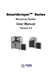
User Manual
Fig. 1. CapitalBio SmartGrid™ and SmartCover™
Precise positioning and adhesion of the SmartGrid™ grid is required to create a
compartmented slide and avoids any possible damage to the printed spots during this
process. CapitalBio SmartStick™ multi-sample grid alignment tool aids aligning the grid to
the slide surface in the correct position. CapitalBio SmartPress™ is a grid pressing tool
which ensures good adhesion of the grid with slide surface. The combined use of these two
tools guarantees firm accurate positioning and strong adhesion of the multi-sample grid on
the slide surface. This prevents any possible cross-contamination caused by liquid sample
leakage.
For Laboratory Research Use Only
Not for Diagnostic Purposes
(a)
(b)
Fig. 2. (a) CapitalBio SmartStick™ and (b) CapitalBio SmartPress™.
CapitalBio Corporation
1
Recommended Protocol
1.
Probe printing
Perform probe printing on the microarray before attaching the adhesive grid. SmartGrid™
dimensions are given below (Fig. 3) for printing reference. When laid down on the microarray
spotter platform, it is recommended to use the top left corner of the slide as the printing starting
point.
2. SmartGrid™ adhesion
Select the appropriate SmartStick™ for the SmartGrid™ being used. For 4-sample grid,
use SmartStick™-A (Cat. No. 430081); for 10- and 12- sample grids, use SmartStick™-B
(Cat. No. 430082). Note: To better fit the slide, the width of the trough could be adjusted
by reposition the lower black strips controlled by the 3 bolts, if using the top left point of
the slide as the printing starting point.
Trough
End
Barrier
SmartGrid™ Slide
Upper
Strip
Slide
Left
Datumline
Upper
Datumline
Lower
Strip
Bolt
Largest array dimension:
3mm×3mm
Protruding feature dimension:
7mm×7mm
Unit:
mm
Largest array dimension:
3.5mm×3.5mm
Protruding feature dimension:
7.5mm×7.5mm
Unit:
mm
Printing starting point
Printing starting point
(a)
Fig. 4. SmartStick™ features
2.1 Remove the protecting kraft paper from the SmartGrid™ (Fig. 5). Be careful not to
damage the glue layer. If the grid sticks to your hand, do not pull hard. Tweezers can be
used to grip the non-adhesive edges of the grid and place it into the trough (Fig. 6).
(b)
SmartGrid™ Slide
SmartGrid™ Slide
Largest array dimension:
2.5mm×2.5mm
Protruding feature dimension:
6mm×6mm
Block dimension:
7mm×7mm
Unit:
mm
Largest array dimension:
2.5mm×2.5mm
Protruding feature dimension:
6mm×6mm
Block dimension:
7mm×7mm
Unit:
mm
Fig. 5. Removing the Kraft paper from
the SmartGrid™.
2.2 Put the grid into the trough with the glue layer facing up. Level the left and upper side
of the grid to the left and upper datumline, respectively (Fig. 6).
Printing starting point
Printing starting point
(c)
(d)
Fig. 3. Printing reference for using (a) 4-sample SmartGrid™/SmartCover™, (b)
8-sample SmartCover™, (c) 10-sample SmartGrid™/SmartCover™ and
(d)12-sample SmartCover™/SmartCover™.
2
Fig. 6. Place SmartGrid™ into the
trough.
3
2.3 Carefully place the microarray slide into the trough with the spotted-side facing down.
Firstly, place the end without the barcode flush to the raised end barrier, then slowly
lower the slide into the trough, aligning the edge with the black guide strips (Fig. 7).
Progressively contact the grid positioned in the trough until the right-hand barcoded
end of the slide is lowered fully onto the grid.
2.4 Important! Carefully press on the back of the slide with the forceps to ensure contact
with all glued surfaces (Fig. 8). Be careful not to press too hard as to damage the slide.
3. SmartCover™ positioning
Remove the PE film packing of SmartCover™. If plastic fragments are found on the
SmartCover™, blow them off with an air puffer. Place the microarray slide in an
appropriate reaction cassette with the printed side facing up (Fig. 10).
SmartGrid™
Fig. 10 Positioning of slide with SmartGrid™ in IncuSet™
protein incubation cassette.
Fig. 7. Microarray slide alignment in the
SmartStick™.
Fig. 8. Pressing with a forceps.
2.5 Check by eye to see if the grid is aligned correctly on the slide and that the grid is
firmly adhered to the slide before removing the slide from the SmartStick™.
2.6 Place the slide into a trough of the SmartPress™ with gridded-side facing upwards.
Holding the SmartPress™ template with one hand, press the grid firmly home against
the slide surface with 2-3 uniform motions of the roller (Fig. 9).
Put the SmartCover™ onto the slide. Make sure that the side with the protruding features
faces down (Fig. 11).
Solution
Port
Solution
adding hole
SmartCover™
Fig. 11. Positioning of SmartCover™ on the slide in IncuSet™.
Roller
SmartPress™ template
Fig. 9. Press the grid home with SmartPress™.
4
5
4. Reaction reagent addition: Take up the reagent solution using an appropriate pipette.
Put the pipette tip vertically into the solution port at the corner of each block of
SmartCover™. When the tip just touches the slide surface, slowly release the solution to
fill the space between the protruding features and the slide surface (Fig. 12). Take care to
not introduce bubbles. The recommended reagent volumes are listed in Table I.
Maintenance
1. CapitalBio SmartGrid™ and SmartCover™ are one-use consumables. Repeated usage is not
recommended.
2. CapitalBio SmartStick™ and SmartPress™ should be cleaned with a clean piece of towel or
tissue paper.
3. Store all items carefully in a cool and dry place and avoid contact with water, oil and other
chemicals.
4. After using for a period of time, check the SmartStick™ to ensure the 6 bolts have not
loosened. Retighten the bolts with an appropriate screwdriver, if loose.
Information
Coverslip
Chip Hybridization. For convenience and high signal reliability, hybridization is best
performed using a CapitalBio BioMixer™ II Microarray Hybridization Station (Cat. No.
120030) and HybSet™ Microarray Hybridization Cassette (Cat. No. 420010) which both help
to reduced edge-effects. The enhanced quality of hybridization is attested in recent publications
such as Patterson et al (2006) Nature Biotechnology 24:1140-1150 and Shi et al (2006) Nature
Biotechnology, 24:1151-1161.
Chip
Chip Incubation Cassette
Fig. 12. Schematic diagram of manipulation.
Table I. Recommended reagent volumes for each block of SmartCover™
Type of SmartCover™
4-sample
8-sample
10-sample
12-sample
Reagent Volume (μl)
13.5
18
20-30
20-30
CapitalBio Corporation
18 Life Science Parkway
Changping District
Beijing 102206
P. R. China
Tel: 86-10-80726868
Fax: 86-10-80726782
[email protected]
www.capitalbio.com
6