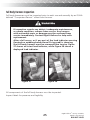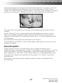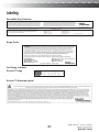
1
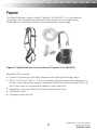
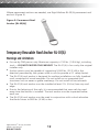
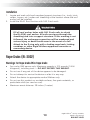
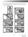
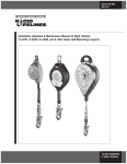
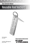
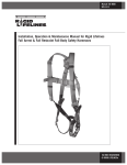
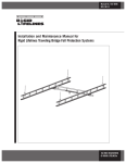
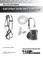
User Instruction Manual
Rigid Lifelines® Gravity Guard™ Roofer’s Kit
Part Number: RL-RK1
ISO 9001: 2008 Registered
Manual 103-0064
General Safety Information
Under Penalty of Law
■
This User Instruction Manual is not to be removed except by the user of this
equipment.
Current User Instruction Manuals must always be available to the user.
Read and understand these instructions before using equipment.
■ Do not throw away these instructions.
■
■
Misuse or failure to follow warnings and instructions may
result in serious personal injury or death.
Users must read and understand the User Instruction Manual
provided with the product and be properly trained by
their employer prior to use per OSHA 29 CFR 1910.66 and
1926.503 or applicable local standards.
Compliant fall protection and emergency rescue systems help
prevent serious injury during fall arrest.
For instructions about proper use, refer to supervisor, User
Instruction Manual, or call Rigid Lifelines at: 844-467-4443.
Rigid Lifelines® Gravity Guard™
Roofer’s Kit Manual
844-467-4443
2
Purpose
The Rigid Lifelines® Gravity Guard™ Roofer’s Kit (RL-RK1) is a cost-effective,
compliant, and complete personal fall arrest system for roof applications
contained in a storage bucket for easy transporting and storage.
Figure 1: Rigid Lifelines® Gravity Guard™ Roofer’s Kit (RL-RK1)
Model RL-RK1 includes:
■
Evolve™ Lightweight Full Body Harness with mating buckle leg straps.
■
50 ft. (15.24 m) of 5/8 in. (1.6 cm) diameter polyester rope with attached 3 ft.
(0.9 m) shock absorbing manual rope grab. Minimum tensile strength 6,000 lb.
with snap hook on one end and taped on the other end.
■
Reusable roof anchor [RL-01(A)] with attachment D-ring.
■
Installation Nails.
■
Storage bucket with lid.
3
Rigid Lifelines® Gravity Guard™
Roofer’s Kit Manual
844-467-4443
Table of Contents
General Safety Information
2
Purpose
3
General Instructions For Use
5
General Limitations For Use
6
Fall Arrest System Components
6
Anchorage Requirements
7
Connection Compatibility Limitations
8
System Compatibility
9
Roof Anchors and Roof Fall Protection System Kits
9
Temporary and Permanent Roof Anchors
11
Temporary Reusable Roof Anchor [RL-01(A)]
12
Rope Grabs (RL-3002)
13
Warnings For Vertical Lifelines
14
Connector System Compatibility
14
Full Body Harness
15
Materials
20
Installation of Gravity Guard™ Roofer’s Kit Components
20
Clearance Requirements
21
Swing Falls
23
Training
24
Inspection And Maintenance
24
Frequency
24
Cleaning And Storage
30
Servicing
30
Labeling
30
Service Policy
35
Warranty
Back Cover
Rigid Lifelines® Gravity Guard™
Roofer’s Kit Manual
844-467-4443
4
General Instructions For Use
■
For use by ONE person only. Maximum capacity is 310 lbs. (140.6 kg), including
tools — DO NOT EXCEED THIS WEIGHT.
■
Anchor points must be capable of supporting 5,000 lbs. (22.2 kN) in the
direction permitted by the system while in use (or provide a 2:1 safety factor).
■
All instructions, warnings and requirements pertaining to the individual system
components must be read, understood and followed.
■
Rope grab must be oriented on the lifeline with the engraved arrow pointing
toward the roof anchor for proper operation of the system.
■
Maximum system arrest force is 900 lbs. (4 kN).
■
Failure to follow all instructions and limitations on the use of this equipment
may result in serious personal injury or death.
■
Before using a personal fall arrest system, employees shall be trained in
accordance with the requirements of OSHA 29 CFR 1910.66 in the safe use
of the system and its components.
■
Prior to each use, inspect all personal fall arrest system equipment for wear,
damage, and other deterioration. Defective components must be removed from
service immediately in accordance with the requirements of OSHA 29
CFR 1910.66 and 1926.502.
■
Thoroughly evaluate and plan all elements of your fall protection system(s)
before using your equipment. Make sure that your system is appropriate for
your needs and facility. Also be sure to calculate fall clearance and swing fall
clearance.
■
Users must have a rescue plan and the means to implement it. This plan must
provide prompt employee rescue or assure that employees have the ability to
rescue themselves in the event of a fall.
■
Store this equipment in a cool, dry, and clean environment that is out of direct
sunlight when not in use.
■
After a fall occurs, this equipment must be removed from service and destroyed
immediately.
■
Never use fall protection equipment for purposes other than those for which
it was designed. Fall protection equipment should never be used for towing or
hoisting.
■
Use in a highly corrosive or caustic environment dictates a more frequent
inspection and servicing program to ensure that the integrity of the system is
maintained.
■
Always check for obstructions below the work area to make sure potential fall
path is clear.
■
Allow adequate fall clearance below the work surface.
5
Rigid Lifelines® Gravity Guard™
Roofer’s Kit Manual
844-467-4443
General Limitations For Use
■
This equipment is designed to be used in temperatures ranging from -40ºF to
+130ºF (-40°C to +54°C).
■
Do not expose this equipment to chemicals or harsh solutions that may have a
harmful effect. Contact Rigid Lifelines with any questions.
■
Use caution when working with this product near moving machinery, electrical
hazards, sharp edges, or abrasive surfaces, as contact may cause equipment
failure, personal injury, or death.
■
Minors, pregnant women, and anyone with a history of back and/or neck
problems should not use this equipment.
■
Do not use or install equipment without proper training from a “Competent
Person,” as defined by OSHA 29 CFR 1926.32(f).
■
Only Rigid Lifelines, or entities authorized in writing by Rigid Lifelines, shall make
repairs or alterations to the equipment.
■
All synthetic material must be protected from slag, hot sparks, open flames, or
other heat sources. The use of heat resistant materials is recommended in these
applications.
Fall Arrest System Components
System Components Overview
A complete fall arrest system consists of the following components: Anchorage,
Body Support, and Connecting Devices.
Note: For continuous protection, more than one system may be needed.
Anchorage
OSHA 29 CFR 1926.502 states that an anchorage, “Shall be independent of any
anchorage being used to support or suspend platforms and capable of supporting
at least 5,000 lb. (22.2 kN) per employee attached, or shall be designed, installed,
and used as follows: as part of a complete personal fall arrest system which
maintains a safety factor of at least two; and under the supervision of a qualified
person.”
Body Support
A body support is the component of a personal fall arrest system that is worn
on or around the body. Per OSHA 29 CFR 1926.502 (effective January 1, 1998),
body belts are not acceptable* as part of a personal fall arrest system. Full body
harnesses must be used for all fall arrest systems.
* Note: The use of a body belt is acceptable in a positioning device system.
Rigid Lifelines® Gravity Guard™
Roofer’s Kit Manual
844-467-4443
6
Connecting Devices
A connecting device is the link between the body support and anchorage.
Connecting devices will vary depending on the application.
Anchorage Requirements
All anchorages to which the Personal Shock Absorbers and Shock Absorbing
Lanyards attach must meet the requirements of OSHA 29 CFR 1910.66 and ANSI
Z359.1-2007. OSHA states:
Anchorages to which personal fall arrest equipment is attached shall
be capable of supporting at least 5,000 pounds (22.2 kilonewtons) per
employee attached, or shall be designed, installed, and used as part of a
complete personal fall arrest system which maintains a safety factor of at
least two, under the supervision of a qualified person.
ANSI Z359.1-2007 states that anchorages in a personal fall arrest system must have
strength capable of sustaining static loads applied in all directions permitted by the
system of at least:
(a) Two times the maximum arrest force permitted on the system with
certification, or
(b) 5,000 lb. (22.2 kN) in the absence of certification
When more than one personal fall arrest system is attached to the anchorage, the
strength in (a) and (b) must be multiplied by the number of personal fall arrest
systems attached to the anchorage.
Anchorages used in controlled descent and rescue systems must be capable of
supporting loads of 3,100 ft-lb. (13.8 kN) for non-certified anchorages or a 5:1
safety factor for certified anchorages per ANSI Z359.4-2007.
Anchorages used in restraint systems must be capable of supporting loads of 1,000
ft-lb. (4.5 kN) for non-certified anchorages or two times the foreseeable force for
certified anchorages per ANSI Z359.2-2007.
Anchorages used in work positioning systems must be capable of supporting loads
of 3,000 ft-lb. (13.3 kN) for non-certified anchorages or two times the foreseeable
force for certified anchorages per ANSI Z359.2-2007.
Anchorages should be located as vertically as possible above the user’s head and be
positioned as not to exceed the maximum allowable free fall for the system.
7
Rigid Lifelines® Gravity Guard™
Roofer’s Kit Manual
844-467-4443
Connection Compatibility Limitations
All Rigid Lifelines® equipment must be coupled to compatible connectors. OSHA 29
CFR 1926.502 prohibits snap hooks from being engaged to certain objects unless
two requirements are met:
1. It must be a locking type snap hook.
2. It must be “designed for” making such a connection.
a. “Designed for” means that the manufacturer of the snap hook specifically
created the snap hook to be used to connect to the equipment in
question.
The following conditions can result in rollout* when a non-locking snap hook is
used. Avoid the following connections (also see Figure 2):
■
Direct connection of a snap hook to horizontal lifeline.
■
Two (or more) snap hooks connected to one D-ring.
■
Two snap hooks connected to each other.
■
A snap hook connected back on its integral lanyard.
■
A snap hook connected to a webbing loop or webbing lanyard.
Improper dimensions of the D-ring, rebar, or other connection point in relation
to the snap hook dimensions that would allow the snap hook keeper to be
depressed by a turning motion of the snap hook.
* Rollout: A process by which a snap hook or carabiner unintentionally disengages
from another connector or object to which it is coupled. (ANSI Z359.0-2007)
■
Figure 2
Rigid Lifelines® Gravity Guard™
Roofer’s Kit Manual
844-467-4443
8
System Compatibility
All Rigid Lifelines® protection products are designed for use with Rigid Lifelinesapproved components. Substitution or replacement with non-approved component
combinations or subsystems or both may affect or interfere with the safe
function of each other and endanger the compatibility within the system. This
incompatibility may affect the reliability and safety of the total system.
Roof Anchors and Roof Fall Protection System Kits
Before Installing Any Roof Anchor or Roof Fall Protection System
■
Carefully inspect to ensure that it is in usable condition.
■
Check for missing or damaged parts.
■
Do not use if any component does not operate properly or appears to be
damaged in any way.
■
Refer to the inspection section of this manual.
■
Only trained and competent personnel should install and use this equipment.
Fall Clearance
Anchor and system must be installed and used in such a manner as to minimize the
potential for a swing fall hazard and limit free fall distance to 6 feet (1.8 m) or less.
Ensure that the anchor point selected is at a height that will not allow a lower level
to be struck should a fall occur. To ensure adequate fall clearance, consider the
following:
■
Rope grabs have a maximum fall arrest distance of 39 in. (1 m).
■
Synthetic rope lifelines may stretch up to 5%. For synthetic rope lifelines, add
1 ft. (0.3 m) of fall clearance for each 20 feet (6 m) of rope above the
connection point.
■
Always remember that shock absorbers will elongate when subjected to
fall arrest forces. Refer to the labels on the connecting device to obtain the
maximum elongation distance.
■
In addition to the above, it is essential to consider other components and
variables, including but not limited to the height to the worker’s back D-ring, the
length of the lanyard, the position of the worker in relation to the anchorage,
and potential harness stretch of up to 1 ft. (0.3 m).
■
Rigid Lifelines recommends that a 3 ft. (0.9 m) safety factor be added to all fall
clearance calculations.
■
Call Rigid Lifelines Technical Service if there is any question about calculating fall
clearance.
9
Rigid Lifelines® Gravity Guard™
Roofer’s Kit Manual
844-467-4443
General Roof Anchor Warnings
■
Fall arrest systems must be rigged in accordance to regulatory requirements. All
instructions and warnings provided with the components of the personal fall
arrest system must be read, understood, and followed.
■
Make sure that all connections within the fall arrest system are compatible.
■
The anchorage connector must be compatible with the snap hook or carabiner
of the connecting device and must not be capable of causing a load to be
applied to the gate/keeper.
■
Use only locking carabiners, locking snap hooks or other Rigid Lifelines-approved
connectors or connecting devices to attach to this equipment.
■
Never use an anchorage connector which will not allow snap hook or carabiner
gate/keeper to close.
■
Rigid Lifelines roof anchors and roofing system kits are designed FOR USE BY
ONE PERSON ONLY.
■
Never work above the roof anchor (i.e., higher level, dormer, higher roof
structure, etc.) Use of these systems is not suitable when the user is positioned
on an unstable surface, fine grain material, or particulate solids such as sand or
coal.
■
Lifelines must be kept clean.
■
Never allow the lifeline to become slack between the rope grab and roof anchor.
■
Never allow the lifeline to pass under or entwine around arms, legs, neck or any
other obstacle.
■
Do not tie knots in lifelines.
■
Use rope grabs only with the appropriate vertical lifeline included in the system
kit.
■
Do not use system if rope grab does not lock onto the lifeline.
■
The structure that this anchor (system) is attached to must be capable of
supporting 5,000 lbs. (22.2 kN) per user attached; or be designed, installed, and
used, under the supervision of a qualified person, as part of a complete personal
fall arrest system which maintains a safety factor of at least two.
■
All roof anchors, when installed per Rigid Lifelines instructions as part of a
Rigid Lifelines personal fall arrest system, meet the OSHA anchorage strength
requirement of maintaining a safety factor of at least two.
Rigid Lifelines® Gravity Guard™
Roofer’s Kit Manual
844-467-4443
10
Temporary and Permanent Roof Anchors
Rigid Lifelines® temporary roof anchors are anchorage connectors designed for
roofing applications and are to be used with complete Rigid Lifelines Roof Systems.
The RL-01(A) roof anchor (Figure 3) is a reusable anchorage connector designed to
be repositioned as work progresses, provided that the roof anchor has not seen fall
arrest forces and has not been damaged in any way (refer to the inspection section
of this manual). It is recommended that new fasteners/hardware be used each time
the roof anchor is installed.
Figure 3: Reusable Anchorage
Connector [RL-01(A)]
Rigid Lifelines RL-05 roof anchor (Figure 4) may only be used as a single use
temporary anchor point and must not be used where permanent anchors are
needed. Additionally, the RL-05 roof anchor is designed for single use.
Figure 4: Single Use
Temporary Anchor
Point (RL-05)
11
Rigid Lifelines® Gravity Guard™
Roofer’s Kit Manual
844-467-4443
Where permanent anchors are needed, use Rigid Lifelines RL-02(A) permanent roof
anchors (Figure 5).
Figure 5: Permanent Roof
Anchor [RL-02(A)]
Temporary Reusable Roof Anchor RL-01(A)
Warnings and Limitations
■
For use by ONE person only. Maximum capacity is 310 lbs. (140.6 kg), including
tools — DO NOT EXCEED THIS WEIGHT. The RL-01(A) is for use by the original
installer only.
■
Anchor points must be capable of supporting 5,000 lbs. (22.2 kN) in the
direction permitted by the system while in use (or provide a 2:1 safety factor).
■
The RL-01(A) roof anchor is designed for rooftop installations on fully sheathed
roofs comprised of wood members. Do not install on un-supported roof
structures such as eaves or gable overhangs. Do not install on fascia boards.
■
The RL-01(A) roof anchor must be installed at least 2 ft. (0.6 m) from any roof
edge.
■
Due to the fatiguing of the nails, it is recommended that new nails be used
every time the anchor is installed. The roof anchor must be inspected before
each use.
■
The RL-01(A) roof anchor must be used in conjunction with a shock absorber
that limits forces to 900 lbs. (4 kN) or less.
Rigid Lifelines® Gravity Guard™
Roofer’s Kit Manual
844-467-4443
12
Installation
1. Locate and mark solid roof members/support structures (i.e., studs, joists,
rafters, trusses, etc.) under roof sheathing at the location where the roof
anchor will be installed.
2. Install the RA-01 Roof Anchor with 16D 3-inch nails.
Fill all roof anchor holes with 16D 3-inch nails to attach
the RL-01(A) roof anchor. All nails must pass through the
sheathing and into a support structure. If this warning is not
followed, the anchorage connection will be weakened and
serious injury or death could occur in the event of a fall.
Attach to the D-ring only with a locking snap hook, locking
carabiner, or other Rigid Lifelines-approved connector or
connecting device.
Rope Grabs (RL-3002)
Warnings For Rope Grabs/Wire Rope Grabs
■
For use by ONE person only. Maximum capacity is 310 pounds (140.6
kilograms), including tools — DO NOT EXCEED THIS WEIGHT.
■
Do not use if any part of the device appears to be damaged.
■
Do not attempt to service the device or alter it in any way.
■
Attach the device to appropriate vertical lifelines only.
■
Do not use this product on unstable surfaces, fine grain materials, or
particulate solids (ex: sand or coal).
■
Maximum arrest distance: 39 inches (1 meter).
13
Rigid Lifelines® Gravity Guard™
Roofer’s Kit Manual
844-467-4443
Warnings For Vertical Lifelines
■
Rigid Lifelines® vertical lifelines have a minimum tensile strength of 6,000
pounds (27 kilonewtons). Note: OSHA requires a minimum tensile strength of
5,000 pounds (22.2 kilonewtons).
■
Lifelines must be attached independently of the working surface and anchored
above the user to prevent a swing fall.
■
Lifelines must be kept clean.
■
Never allow the lifeline to become slack or to pass under or entwine around
arms, legs, neck, or any other obstacle.
■
Do not tie knots in lifelines.
■
When evaluating your workspace for fall clearance, consider these lifeline
elongation characteristics in your calculations:
Rope stretch = 5%
Wire rope stretch = 0.5%
Connector System Compatibility
■
A Competent Person must ensure compatibility of all connections and all system
elements.
■
Do not use the system if the device does not lock onto the lifeline or if any
component in the system does not operate properly.
■
Install and use device and lifeline in a manner that reduces potential swing fall.
■
Allow sufficient clearance in the event of a free fall. For synthetic rope lifelines,
add 1 foot (.3 meters) of fall clearance for every 20 feet (6 meters) of rope
above the connection point. If a shock absorber is used, you must also allow for
an additional 3.5 feet (1.06 meters) maximum elongation.
■
Rig system to limit free fall distance to 6 feet (1.8 meters) or less.
■
Do not expose this equipment to harmful chemicals or solutions. Contact Rigid
Lifelines with questions.
■
Use caution when working with this product near moving machinery, electrical
hazards, sharp edges, or abrasive surfaces, as contact may cause equipment
failure, personal injury, or death.
■
Minors, pregnant women, and anyone with a history of back and/or neck
problems should not use this equipment.
■
Do not use or install equipment without proper training from a “Competent
Person” as defined by OSHA 29 CFR 1926.32(f).
■
Only Rigid Lifelines, or entities authorized in writing by Rigid Lifelines, shall make
repairs or alterations to the equipment.
Rigid Lifelines® Gravity Guard™
Roofer’s Kit Manual
844-467-4443
14
Rigid Lifelines® Rope Grab (RL-3002) assembly and vertical
lifelines are designed for use with Rigid Lifelines approved
components. Substitution or replacement with non-approved
component combinations, subsystems, or both may reduce the
equipment function and endanger the system compatibility.
This incompatibility may affect the reliability and safety of the
total system.
Always use Rigid Lifelines Rope Grab assembly with specified
Rigid Lifelines vertical lifelines. Vertical Lifelines must have a
minimum tensile strength of 6,000 pounds (27 kilonewtons).
Full Body Harness
A full body harness must be inspected prior to each use for wear, damage,
and other deterioration. All webbing must be inspected for tears, cuts, fraying,
abrasion, discoloration, or other signs of wear and damage. Sewn terminations
should be secure, complete, and not visibly damaged. No load indicators shall be
deployed. Damaged and other deteriorated and defective components must be
immediately removed from service, in accordance with the requirements of OSHA
29 CFR 1910.66 and 1926.502.
Donning a Vest Style Full Body Harness
Not all fall protection components are rated for the same user
weight capacity. Only use components rated for the same
weight capacity.
There must be a functional rescue plan if users of fall
protection systems cannot rescue themselves.
Note: Sewn terminations should be secure, complete, and not visibly damaged.
No load indicators shall be deployed. Damaged and other deteriorated and
defective components must be immediately removed from service in accordance
with the requirements of OSHA 29 CFR 1910.66 and 1926.502.
15
Rigid Lifelines® Gravity Guard™
Roofer’s Kit Manual
844-467-4443
Fitting an Evolve™ Full Body Harness
1. Hold the dorsal (back) D-ring of the harness and shake to allow all straps to
fall into place; see Figure 6. Straps must not be buckled or twisted.
Figure 6
2. Slip shoulder strap over one shoulder, then pull the other shoulder strap
around the back and over the second shoulder — much like putting on a
jacket; see Figures 7 and 8. The dorsal D-ring will be located on your back
while the chest strap is located in the front. Straps must not be tangled as the
harness hangs freely from shoulders.
Figure 7 Figure 8
Rigid Lifelines® Gravity Guard™
Roofer’s Kit Manual
844-467-4443
16
3. Pull one leg strap between your legs and connect it to the opposite end on the
same side; see Figures 9 through 16. Repeat with second leg strap. Ensure that
the leg straps are not twisted or crossed. Leg straps must be comfortably snug
to achieve proper adjustment.
Figure 9
Figure 10
Figure 11
Figure 12
Figure 13
Figure 14
Figure 15
Figure 16
17
Rigid Lifelines® Gravity Guard™
Roofer’s Kit Manual
844-467-4443
Failure to have the leg straps of the Evolve™ Full Body
Harness properly adjusted during fall arrest may result in
serious personal injury or death.
4. Fasten the chest strap just above the nipple line; see Figures 17 and 18. Chest
strap should be snug with excess strap-length secured through the web keepers;
see Figures 19 and 20.
Figure 17
Figure 18
Figure 19
Figure 20
5. Adjust shoulder straps* with the two adjusters located at the lower end of the
shoulder strap. Adjust the left and right sides to the same length; see Figure 21.
Figure 21
Rigid Lifelines® Gravity Guard™
Roofer’s Kit Manual
844-467-4443
18
The chest strap (and front D-ring, if applicable) must be centered on your lower
chest.
*Adjustment of the shoulder straps may cause the dorsal D-ring to move and may
need to be repositioned up or down as needed to achieve correct position; see
Figure 22.
Figure 22
6. After all straps have been tightened and harness fits snugly, secure all excess
straps through the web keepers; see Figures 23 and 24.
Figure 23
Figure 24
19
Rigid Lifelines® Gravity Guard™
Roofer’s Kit Manual
844-467-4443
Materials
Webbing
All Rigid Lifelines® full body harnesses are constructed with 1¾ in (44 mm)
polyester webbing.
Hardware
All hardware on the full body harness meet the ANSI Z359.1-2007 standard and
OSHA 29 CFR 1910.66 and 1926.502 requirements.
Installation of Gravity Guard™ Roofer’s Kit Components
1. Install Roof Anchor
Refer to pages 12-13 of this manual for installation of the RL-01(A) roof
anchor.
2. Connect Lifeline Snap Hook to Roof Anchor D-ring
The lifeline snap hook must be connected to the roof anchor D-ring to ensure
that the rope grab is pointed in the correct direction for proper operation.
Ensure that the snap hook completely closes and locks; see Figure 25.
Engraved arrow marking on rope grab must point toward
lifeline snap hook for system to operate correctly and ensure
user safety. (See Figure 26.)
Figure 25
Figure 26
Attach lifeline snap hook to roof anchor D-ring
3. Connect Lanyard Shock Absorber Pack Snap Hook To Full Body Harness
Dorsal (Back) D-Ring
Ensure that snap hook completely closes and locks.
Rigid Lifelines® Gravity Guard™
Roofer’s Kit Manual
844-467-4443
20
Clearance Requirements
These illustrations are an example of how to calculate fall clearance when using a
self-retracting lanyard or a shock-absorbing lanyard.
Image 1 shows a self-retracting lanyard anchored overhead with the other end
connected to the dorsal D-ring of a full body harness. When positioning a selfretracting lanyard, include the following distances in your calculations.
Using the Defy™ Self-Retracting Lanyard will require a total fall clearance of
approximately 7.5 feet (2.3 meters) as measured from the working level to the
nearest obstruction below. The total fall clearance combines the sum of the
maximum allowable fall arrest distance of 54 inches or 4.5 feet (1.4 meters) and
the safety factor of 3 feet (0.9 meters).
Image 2 shows a shock-absorbing lanyard anchored overhead with the other end
connected to the dorsal D-ring of a full body harness. Note that the length of
your shock-absorbing lanyard in relation to where it is attached is directly related
to the amount of fall clearance that you will need. When using a shock-absorbing
lanyard, include the following distances in your calculations.
Using the 6 Foot Connex™ Shock-Absorbing Lanyard will require a total fall
clearance of approximately 18 feet (5.5 meters) as measured from the anchorage
point of lanyard to the nearest obstruction below. The total fall clearance combines
the sum of the length of the lanyard, the maximum elongation of the lanyard (4
feet or 1.2 meters), the average distance between the worker’s dorsal D-ring (5 feet
or 1.5 meters), and the safety factor (3 feet or 0.9 meters).
21
Rigid Lifelines® Gravity Guard™
Roofer’s Kit Manual
844-467-4443
Using an extended free fall (12 foot) Connex Shock Absorbing Lanyard will require
a total fall clearance of approximately 20 feet (6.1 meters) when anchored at foot
level and measured from the anchorage point of lanyard to the nearest obstruction
below. The total fall clearance combines the sum of the length of the lanyard, free
fall distance, the maximum elongation of the lanyard (5 feet or 1.5 meters), the
average distance between the worker’s dorsal D-ring, (5 feet or 1.5 meters), and
the safety factor (3 feet or 0.9 meters).
Rigid Lifelines® Gravity Guard™
Roofer’s Kit Manual
844-467-4443
22
Swing Falls
To minimize the possibility of a swing fall, work as directly under the anchorage
connector as possible. Striking objects horizontally, due to the pendulum affect,
may cause serious injury. Swing falls also increase the vertical fall distance of a
worker, compared to a fall directly below the anchorage connector. Swing falls may
be reduced by using overhead anchorage connectors that move with the worker.
Worker’s accessing areas greater than 30° off-plumb from
overhead anchorage are at a higher risk for severe injury.
Striking objects horizontally due to the pendulum effect of a
swing fall may cause serious injury or death.
23
Rigid Lifelines® Gravity Guard™
Roofer’s Kit Manual
844-467-4443
Training
Employers are responsible for providing training to any employee who may be
exposed to fall hazards. Training will enable an employee to recognize and reduce
fall hazards. Training must be conducted by a Competent or Qualified Person.
Trainer and trainees must not be exposed to fall hazards during the training course.
Inspection And Maintenance
Rigid Lifelines Gravity Guard™ Roofer’s Kit fall protection system must be visually
inspected by the user before each use and inspected by a Competent Person on a
regular basis.
If inspection reveals any defect, inadequate maintenance, or unsafe
condition, remove from service immediately.
Any equipment that has been subjected to the forces of arresting a fall
must be removed from service immediately.
Note: Only manufacturer, or entities authorized in writing by the
manufacturer, may make repairs to the product. Otherwise, equipment
must not be altered in any way.
Frequency
All equipment must be inspected prior to each use according to the manufacturer’s
instructions. Annual inspections must also be performed by an OSHA defined
Competent Person other than the user. All equipment should be inspected by a
Qualified Person on a regular basis.
All equipment must be free of corrosion, chemical attack, alteration, excessive
heating, or extreme wear.
All markings must be legible and attached to the equipment.
Perform the following procedures (if applicable) to your product and/or system:
Roof Anchor Inspection
Inspect product for any of the following: bent, cracked, distorted, worn,
malfunctioning or damaged parts; rough or sharp edges; loose fasteners or missing
parts/components; corrosion; deterioration; signs that indicate the product has
been subjected to a fall arrest; or any other indications of damage/problems that
may affect the integrity and operation of the product. If in doubt, contact the
manufacturer.
Rigid Lifelines® Gravity Guard™
Roofer’s Kit Manual
844-467-4443
24
Full Body Harness Inspection
Full body harnesses must be inspected prior to each use and annually by an OSHAdefined “Competent Person” other than the user.
If inspection reveals any defect, inadequate maintenance,
or unsafe condition, remove from service. Any harness
with noticeable wear or damage must be removed from
service immediately. Contact Rigid Lifelines for help with
replacement.
After a fall occurs, or if any part of the load indicator warning
(located on webbing below dorsal D-ring pad) is showing,
the full body harness must be removed from service. Figure
27 shows an intact load indicator, while Figure 28 shows a
deployed load indicator.
Figure 27
Figure 28
All components of the full body harness must be inspected.
Inspect labels for presence and legibility.
25
Rigid Lifelines® Gravity Guard™
Roofer’s Kit Manual
844-467-4443
To Inspect Webbing
Bend a portion of the webbing 6-8 in. (15-20 cm) into an upside-down ‘U’ shape;
see Figure 29. Continue along all webbing inspecting for tears, cuts, fraying,
abrasion, discoloration, burns, holes, mold, pulled or broken stitches, or other signs
of wear and damage.
Figure 29
Adjust all keepers, buckles, padding, and D-ring to inspect webbing hidden by
these components.
Sewn terminations must be secure, complete, and not visibly damaged.
Check all buckles for damage, distortion, cracks, breaks, and rough or sharp edges.
Inspect for any unusual wear, frayed or cut fibers, or broken stitching of the buckle
attachments. Make sure buckles properly engage; see Figure 30.
Figure 30
Rigid Lifelines® Gravity Guard™
Roofer’s Kit Manual
844-467-4443
26
Tongue buckle/grommet tongues should be free of distortion in shape and motion.
They should overlap the buckle frame and move freely back and forth in their
socket. The roller should turn freely on frame. Inspect for loose, distorted, or broken
grommets; see Figure 31. Webbing should not have additional punched holes.
Figure 31
The outer bars and center bars on friction and slotted mating buckles must be
straight.
Ensure that the Quick-Connect buckle’s dual-tab release mechanism is free of
debris and engages properly. Double-check the buckle locking mechanism by
tugging on both halves of the buckle to make sure it is firmly connected and will
not disengage.
All markings must be legible and attached to the product.
All hardware must be free of cracks, sharp edges, deformation, corrosion, or any
evidence of defect.
Rope Grab Inspection
Inspect product for any of the following: bent, cracked, distorted, worn,
malfunctioning or damaged parts; rough or sharp edges; loose fasteners or missing
parts/components; corrosion; deterioration; signs that indicate the product has
been subjected to a fall arrest; or any other indications of damage/problems that
may affect the integrity and operation of the product. If in doubt, contact the
manufacturer.
Be sure that rope grab operates properly, freely and only as intended by the
manufacturer.
27
Rigid Lifelines® Gravity Guard™
Roofer’s Kit Manual
844-467-4443
Lanyard/Vertical Lifeline Inspection
When inspecting lanyards and vertical lifelines, begin at one end and work to the
opposite end. Slowly rotate the lanyard or lifeline so that the entire circumference
is checked; see Figure 32.
Webbing/Stitches: While bending webbing over a pipe or mandrel, observe
each side of the web lanyard. This will reveal any cuts, snags, or breaks. Swelling,
discoloration, cracks, and/or charring are obvious signs of chemical or heat
damage. Observe closely for any breaks in the stitching.
Figure 32
Rope: Rotation of the rope lifeline while inspecting from end-to-end will bring to
light any fuzzy, worn, broken or cut fibers; see Figures 33 and 34. Weakened areas
from extreme loads will appear as a noticeable change in original diameter. The
rope diameter should be uniform throughout, following a short break-in period.
Figure 33
Rigid Lifelines® Gravity Guard™
Roofer’s Kit Manual
844-467-4443
Figure 34
28
Snap Hooks/Thimbles: Inspect closely for hook and eye distortions, cracks,
breaks, corrosion, pitted surfaces, and rough or sharp edges; see Figure 35.
The gate (keeper) should seat into the nose without binding and should not be
distorted or obstructed. The gate spring should exert sufficient force to firmly close
the gate. When the gate is closed, the locking mechanism MUST prevent the gate
from opening. The thimble must be firmly seated in the eye of the splice, and the
splice should have no loose or cut strands. The edges of the thimble must be free
of sharp edges, distortion, or cracks.
Figure 35
Pack-Type Shock Absorber: The outer portion of the pack should be examined
for burn holes and tears. Stitching on areas where the pack is sewn to the lanyard
or hardware should be examined for loose strands, rips, deterioration or other signs
of activation; see Figures 36 and 37.
Figure 36
Figure 37
29
Rigid Lifelines® Gravity Guard™
Roofer’s Kit Manual
844-467-4443
Carabiners: Inspect product for any of the following: bent, cracked, distorted,
worn, malfunctioning or damaged parts; rough or sharp edges; loose fasteners or
missing parts/components; corrosion; deterioration; signs that indicate the product
has been subjected to a fall arrest; or any other indications of damage/problems
that may affect the integrity and operation of the product. If in doubt, contact the
manufacturer.
Check the carabiner to be sure that it operates freely and only as intended by the
manufacturer. Ensure that gate (keeper) is seated properly without binding and is
not distorted or obstructed. The gate spring should exert sufficient force to firmly
close the gate. When the gate is closed, the locking mechanism MUST prevent the
gate from opening.
Devices that do not pass inspection or have been subjected
to fall arresting forces must be removed from service.
Cleaning and Storage
Basic care of all Rigid Lifelines® Fall Protection equipment will prolong the durable
life of the unit and will contribute toward the performance of its vital safety
function. Proper storage and maintenance after use are as important as cleansing
the equipment of dirt, corrosives, or contaminants. Storage areas should be clean,
dry and free of exposure to fumes or corrosive elements.
Clean equipment periodically with a sponge dampened in a mild solution of water
and commercial soap or detergent to remove any dirt, paint, or other materials that
may have accumulated. Wipe dry with a clean cloth and/or hang freely to dry away
from excessive heat, steam, or long periods of sunlight. Store in a clean, dry area
when not in use.
Servicing
Servicing of Rigid Lifelines® equipment must only be carried out by Rigid Lifelines
or persons or entities authorized in writing by Rigid Lifelines. A record log of
all servicing and inspection dates for this equipment must be maintained. Only
original Rigid Lifelines replacement parts are approved for use in this equipment.
Non-repairable devices that do not pass inspection must be disposed of in a
manner to prevent inadvertent further use. Contact Rigid Lifelines at 844.467.4443
if you have any questions.
Rigid Lifelines® Gravity Guard™
Roofer’s Kit Manual
844-467-4443
30
Labeling
Reusable Roof Anchor
Instructions: This anchor when installed in accordance with the manufacturer’s instructions
included at the time of shipment will provide an anchor point at the peak of the roof which is suitable
for use with compliant fall arrest systems. The roof peak anchor should be used in conjunction with
roof bracket walk planks when installing conventional roofing systems on truss, rafter and plywood
sheathing construction. Begin by placing the first anchor along the peak of the roof at a point 5 ft.
any deterioration. When working on a flat surface, the anchor can be installed by extending the two
flat plates out, leaving the D-Ring in the middle. This roof anchor must be visibly inspected before
each use and also inspected by a competent person at least every six (6) months from the date of
purchase. Do not use if roof anchor has any signs of cracks, corrosion, dents, deformities, or
bending. Meets ANSI Z359.1 2007, A10-14 OSHA 1910/1926
from the beginning of the roof line. Additional anchors should be placed no more than every 10 ft.,
with the last anchor 5 ft. from the end of the roof line. Remove ridge vents when attaching peak
anchors. Each anchor should be fastened to the roof using 16D 3-inch nails. The center row of holes
must be secured to the plywood sheathing. Use all holes provided in nailing the anchor to the
building structure. Inspect rafter from the inside structure to ensure the wood is sound and free of
Reusable Roof Anchor
Model #: RL-01A
Capacity: 310 lbs.
Anchor Point: Must
withstand 5000 lbs. per
User: 1 Person Max.
worker attached
DO NOT REMOVE THIS LABEL.
Rope Grab
Full Body Harness
Evolve™ logo
Evolve™ Warning Label
31
Rigid Lifelines® Gravity Guard™
Roofer’s Kit Manual
844-467-4443
Evolve™ Fall Indicator
Rigid Lifelines® Gravity Guard™
Roofer’s Kit Manual
844-467-4443
Evolve™ Long Label
32
Notes
________________________________________________
________________________________________________
________________________________________________
________________________________________________
________________________________________________
________________________________________________
________________________________________________
________________________________________________
________________________________________________
________________________________________________
________________________________________________
________________________________________________
________________________________________________
________________________________________________
________________________________________________
________________________________________________
________________________________________________
________________________________________________
________________________________________________
________________________________________________
________________________________________________
33
Rigid Lifelines® Gravity Guard™
Roofer’s Kit Manual
844-467-4443
Notes
________________________________________________
________________________________________________
________________________________________________
________________________________________________
________________________________________________
________________________________________________
________________________________________________
________________________________________________
________________________________________________
________________________________________________
________________________________________________
________________________________________________
________________________________________________
________________________________________________
________________________________________________
________________________________________________
________________________________________________
________________________________________________
________________________________________________
________________________________________________
________________________________________________
Rigid Lifelines® Gravity Guard™
Roofer’s Kit Manual
844-467-4443
34
Service Policy
1. Obtain as much information as possible concerning the problem through
personal observation by yourself or other authorized personnel familiar with
the job and equipment: include model, serial and/or part numbers, voltages,
speeds, and any other special identifying features. Be prepared to discuss the
situation in detail.
2. All authorized labor charges will be based on straight time. Hourly rates,
estimated man hours, and not to exceed total dollar amount required for
corrections are to be agreed upon before authorization is given. There will be
no allowances for overtime except in dire emergencies and then only with prior
approval.
3. A verbal agreement may be reached immediately on both the method of
correction and the approximate cost. A warranty authorization number will be
assigned for the specific incident. A confirming written authorization will be
forwarded to the distributor.
4. The distributor must send an itemized invoice, showing our release number
or invoice number and warranty authorization number after authorized
corrections have been made. A credit memo will be issued by accounting after
the invoice has been received and approved. Warranty charges ARE NOT to be
deducted from outstanding open account invoices under any circumstances.
5. Any field corrections made prior to an authorization by Rigid Lifelines will not
be accepted as a warranty charge or the responsibility of Rigid Lifelines. Any
modification to the equipment made without prior approval of the seller will
void all warranties. A verbal authorization for modification may be obtained, in
which event a warranty authorization number will be assigned for the specific
modification. A confirming written authorization will be forwarded to the
distributor.
35
Rigid Lifelines® Gravity Guard™
Roofer’s Kit Manual
844-467-4443
One-Year Equipment Warranty
Rigid Lifelines® warrants all Rigid Lifelines fall protection soft goods, devices, connectors,
and accessories to be free from defects in material and workmanship for a period of one
(1) year, commencing on the date of shipment to the first retail purchaser (“Purchaser”).
Rigid Lifelines is dedicated to offering superior service and quality products to all of our
customers. If you would like to contact a customer service representative, please call the
following number: 1 (844) 467-4443. We will be happy to assist you in any way that we
can.
These warranties do not extend to equipment which has been subject to misuse, use in
excess of rated capacity, negligent operation, use beyond Rigid Lifelines published service
factors, improper installation or maintenance, adverse environments, and does not apply
to any equipment which has been repaired or altered without Rigid Lifelines written
authorization. This warranty is void for any product that is designed to deform or absorb
energy during a fall event and needs to be replaced after a fall event has occurred.
Written notice of any claimed defect must be given to Rigid Lifelines within thirty (30)
days after such defect is discovered. Rigid Lifelines obligation, and Purchaser’s sole remedy
under this warranty is limited to, at Rigid Lifelines discretion, the replacement or repair
of the equipment at Rigid Lifelines factory or at a location approved by Rigid Lifelines.
THIS WARRANTY IS EXPRESSLY IN LIEU OF ALL OTHER WARRANTIES WHATSOEVER
WHETHER EXPRESS, IMPLIED, OR STATUTORY. SELLER MAKES NO WARRANTY AS TO THE
MERCHANTABILITY OR FITNESS FOR A PARTICULAR PURPOSE OF THE EQUIPMENT AND
MAKES NO OTHER WARRANTY, EITHER EXPRESS OR IMPLIED.
Rigid Lifelines shall not be liable, under any circumstances, for any indirect, special, or
consequential damages including (but not limited to): lost profits, increased operating
costs, or loss of production. This warranty shall not extend to damages including (but not
limited to): lost profits, increased operating costs, or loss of production. This warranty
shall not extend to any components or accessories not manufactured by Rigid Lifelines
(example: casters), with the exception of the components, systems, or accessories involved
with XSPlatforms, and purchaser’s remedy for such components and accessories shall be
determined by the terms and conditions of any warranty provided by the manufacturer of
such components and accessories.
Rigid Lifelines
730 Hemlock Road, Suite 104
Morgantown, PA 19543
Toll Free: (844) 467-4443
Local: (610) 286-8030
Fax: (610) 286-6408
RigidLifelines.com
[email protected]
©2014. All rights reserved. Specifications subject to change without prior notice. RLL-RK0114V1