1
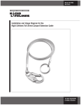
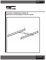
Manual No. 103-0048
REV. 08/14
Installation and Maintenance Manual for
Rigid Lifelines Traveling Bridge Fall Protection Systems
ISO 9001 REGISTERED
© RIGID LIFELINES®
2
TABLE OF CONTENTS
4
Forward......................................................................................................................................
Fall Protection Safety and Considerations................................................................................
5
Fall Protection Component and System Installation Requirements..........................................
6
Installation Instructions..............................................................................................................
6
Performance Testing of Fall Protection Components and Systems..........................................
6
Usage Notes..............................................................................................................................
7
Plain Track Runway Drawing..................................................................................................... 8-9
Trussed Track Runway Drawing................................................................................................ 10-11
Design Factors...........................................................................................................................
12
Preparation.................................................................................................................................
12
Runway Installation...................................................................................................................
13
Splice Installation....................................................................................................................... 14-15
Bridge End Truck Installation.....................................................................................................
16
Runway End Stop Installation....................................................................................................
17
Trolley Installation......................................................................................................................
17
Warning, Safety, or Capacity Labels..........................................................................................
17
Sway Bracing Requirements.....................................................................................................
17
Lateral Bracing for Traveling Bridge..........................................................................................
18
Appendix....................................................................................................................................
19
Fall Arrest Flush Mount Truss Hanger................................................................................
20
FAC-480 Assembly Instructions..........................................................................................
21
Fall Arrest Ceiling Mount Truss Hanger..............................................................................
22
Fall Arrest Ceiling Mount Truss Hanger C-482...................................................................
23
Fall Arrest Ceiling Mount Plain Track Hanger....................................................................
24
Fall Arrest Flush Mount Parallel Mount Plain Track Hanger..............................................
25
Fall Arrest Ceiling Mount Plain Track Cross Mount............................................................
26
Fall Arrest Sloped Hanger..................................................................................................
27
Fall Arrest C-480 Sub Hanger............................................................................................
28
Fall Arrest Ceiling Mount Truss Hanger.............................................................................
29
Fall Arrest Bar Joist Hanger...............................................................................................
30
Fall Arrest C-480 360 Truss Hanger Assembly..................................................................
31
Fall Arrest Flush Mount Plain Track Hanger......................................................................
32
Fall Arrest Ceiling Mount Plain Track Bar Joist Hanger.....................................................
33
Fall Arrest Slope Hanger ...................................................................................................
34
Fall Arrest Hanger ..............................................................................................................
35
Fall Arrest FA-K-CMT-500-BOLT........................................................................................
36
Beam Clip Chart ................................................................................................................
37
Fall Protection Safety and Maintenance Instructions................................................................ 38-40
Annual Fall Protection Systems Inspection Checklist...............................................................
41
Warranty and Service Policy......................................................................................................
44
3
FORWARD
This manual contains important information to help you install, operate, maintain, and
service your new fall protection system. We recommend that you study its contents
thoroughly before putting the system into use. By practicing the recommended
maintenance, with proper installation, and application of correct operating procedures, you
will be assured maximum service from your fall protection system.
The systems described in this manual are intended for indoor service. Systems
used for outdoor service require special consideration.
INSTALLATION:
Before attempting to install your new system, the following items must be understood...
1. It is the customer’s responsibility to ensure that building columns or walls are adequate
to support the system.
2. Systems should not be hung from an existing building structure without first consulting
a qualified architect or engineer for the purpose of determining the structure’s
adequacy.
Fall Arrest Considerations
NOTE: DO NOT MOUNT THE SYSTEM TO ANY
STRUCTURE UNLESS YOU ARE SURE THE
STRUCTURE CAN SAFELY SUPPORT THE LOADS
IMPOSED UPON THE STRUCTURE. FAILURE TO CHECK
THIS ITEM CAN RESULT IN SEVERE BODILY INJURY OR
DEATH.
Per OSHA 1926.500, Subpart M, “Anchorages used for attachment of personal fall arrest
equipment shall be independent and capable of supporting at least 5000 pounds per
employee attached, or designed installed and used as part of a complete fall arrest system
which maintains a safety factor of two (2) and under the supervision of a qualified person.
Personal fall arrest systems when stopping a fall shall:
1.
2.
Be rigged so that an employee cannot contact any lower level.
Bring an employee to a complete stop and limit maximum deceleration distance an
employee travels to 3.5 feet.
4
FALL PROTECTION SAFETY AND CONSIDERATIONS
Fall Protection Safety
1. Remove systems and components from service IMMEDIATELY if they have been
subjected to fall impact until inspected by a competent person and deemed
undamaged and suitable for use.
2. Promptly rescue employees in the event of a fall, or assure that they are able to
rescue themselves.
3. Inspect systems prior to each use for wear, damage, and other deterioration; and
remove defective components.
4. Do NOT attach fall arrest systems to guard rail systems or hoists.
5. Do NOT attach fall arrest systems to crane bridges unless specifically designed for
such use by a competent engineer.
6. Every fall arrest system should have a rescue plan to recover fallen workers. If the
same fall arrest system will be used to recover a fallen worker, a two man system
must be specified.
7. Workers using fall protection shall follow the “buddy system” by utilizing a spotter.
Fall Protection Considerations
Anyone working in general industry over a height of 4 ft. or more above a lower
level with an unprotected side or edge shall be protected from falling.
Anchorages used for attachment of personal fall arrest equipment shall be certified
for the applied forces by others.
Note: Consult factory for custom design if maximum arresting force exceeds 900 lb.
Check bolts annually for tightness.
5
FALL PROTECTION COMPONENT AND
SYSTEM INSTALLATION REQUIREMENTS
Engineered fall protection components and standard systems displayed in Rigid Lifelines sales
literature meet or exceed all regulations as defined by ANSI Z359, OSHA 1910.66 and OSHA
1926.502 for engineered components.
Rigid Lifelines fall arrest components and systems must be employed and maintained in
accordance with all ANSI and OSHA regulations.
INSTALLATION INSTRUCTIONS
Install components as defined in this manual and in accordance with ANSI and OSHA regulations.
If the system is a standard engineered fall protection system, install the system(s) as defined on the
provided assembly drawings.
If the system has been custom engineered as custom system by Rigid Lifelines, install the
system(s) as defined on the provided custom assembly drawing.
NOTE: Rigid Lifelines fall protection components are similar to crane designs, but
may never be used as a crane.
Never use a Rigid Lifelines fall protection
component or system as a crane or to lift objects,
unless specifically engineered by Rigid Lifelines to
do so.
PERFORMANCE TESTING OF
FALL PROTECTION COMPONENTS AND SYSTEMS
When installed, operated, and maintained in accordance with the supplied Rigid Lifelines
documentation, no acceptance test is requried.
Rigid Lifelines has engineered all systems to exceed OSHA’s requirement that the entire
system provide a safety factor of two over applied loads.
If acceptance testing is requested, Rigid Lifelines recommends following the ANSI
requirements for dynamic performance testing of all Rigid Lifelines fall protection
components and systems. The application of a dynamic performance test, as defined by
ANSI Z359.1-2007 consists of a 220 lb test weight dropped for a total 6-foot free fall
before a 900 lb MAF (maximum arresting force) “ripstitch” energy absorbing lanyard
engages to decelerate the load (reference Z359.1 sections 4.1.2 and 4.2.9). A two-man
system will use two separate weights (using one 900 MAF lanyard per weight), a threeman system will use three separate weights, and so on. ANSI standards are available at
www.ansi.org
6
USAGE NOTES
1.
2.
3.
4.
5.
6.
7.
8.
9.
10.
11.
12.
13.
14.
15.
Read, understand and follow instructions of all component manuals and warnings
before use.
Follow all current requirements of ANSI Z359.
Always perform a hazard analysis before use. Correct all hazards before use.
Inspect system before use, per instruction manual.
Inspect thoroughly by competent person after each fall.
Inspect annually by competent person.
Never load track at an angle greater than 30º from vertical.
Never use system with the attachment point below the D-ring of the harness.
Always have a written rescue plan that defines who will rescue and what equipment
will be used.
Never use without a worker monitor (buddy system).
If a jib boom is provided, never apply a lateral load at the boom tip.
Per OSHA and ANSI, a competent person must provide proper user training
before use.
Never deviate from the above unless you have written permission and authorization
from Rigid Lifelines.
Only for use with self-retracting lanyards (SRL).
Only for use with ANSI full-body fall protection harnesses.
7
8
**IMPORTANT - IF SUPPORT STEEL IS
SLOPED, SPECIAL SLOPED HANGERS
MUST BE USED. CALL YOUR RIGID
LIFELINES SALESPERSON.
***BRACING BRACKETS, #09B0510,
ARE AVAILABLE, FOR USE WITH 1”
DIAMETER PIPE. CALL YOUR RIGID
LIFELINES SALESPERSON.
9
10
**IMPORTANT - IF SUPPORT STEEL IS
SLOPED, SPECIAL SLOPED HANGERS
MUST BE USED. CALL YOUR RIGID
LIFELINES SALESPERSON.
***BRACING BRACKETS, #09B0510,
ARE AVAILABLE, FOR USE WITH 1”
DIAMETER PIPE. CALL YOUR RIGID
LIFELINES SALESPERSON.
11
DESIGN FACTORS
Nameplate bridge capacity represents the rated load on the fall protection bridge. The load
rating of trolleys shall not exceed the bridge rating.
Runway Alignment Tolerance
Span
(2 Runway)
A=3/16” in any
support span
Span
(3 or more Runways)
B=3/16” in any
support span
Straightness
C=1/4” in any
support span
Elevation
D=1/4” in any
support span
Rail to Rail
Elevation
E=1/4” between
adjacent rails
Because Rigid Lifelines Enclosed Track System provides a very high ease of
movement, Rigid Lifelines recommends bridge and runway slope of no more than
1/4” in 20’-0” to prevent drift of bridge or trolley. Diagrams courtesy of MMA MH27.1
and MH 27.2
PREPARATION
1. Before starting the installation, check the material list to be sure you have received all
parts. Systems thaT mount directly to overhead supports with support flush
mount brackets do not require lateral sway bracing.
12
All systems with drop rod hangers must be laterally and
longitudinally braced. Lateral sway bracing is furnished by
others.
RUNWAY INSTALLATION
2. Traveling bridge workstation designs may vary from system to system. The positioning
of support brackets or hangers likewise may vary with building structural arrangement
as well as with track profile.
Establish where the system is to be installed. Bolt the proper mounting support
brackets or hangers to the ceiling beam(s). See Figs. 1a-1b below. Raise the runway
track section and attach it to the brackets or hangers with the appropriate fasteners.
Runways should extend between 4 1/2” and 12” beyond the last support at either end
for plain track runways, up to 48” for trussed runways.
Adjustable roof beam clamp
providing secure fit to
horizontal beams only. Flange
widths range from 2-1/4” to
8”, and a maximum flange
thickness of 7/16”. Alternate
clamps can be provided,
upon request, for larger
beams or for sloped beams
(not horizontal).
(Fig. 1b)
Trussed Track
Hanger
1’-0”
Runway endstops must be aligned longitudinally so bridge
hits end stops simultaneously.
(Fig. 1a)
Plain Track
Hanger
See appendix for hanger
torque specifications.
Note: Each section of plain track must
have at least 2 hangers per track section.
13
SPLICE INSTALLATION
3. If your system has more than one section length of runway track, each additional section
is installed in the same manner as the first, with the addition of a splice joint assembly.
Plain Track: Splice joints should be within 12” of a support bracket or hanger as shown in
AAFig. 2a.
Reinforced Runway: Splice joints should be within 48” of a support bracket or hanger.
The track splice joint is made from a sleeve with a total of eight set screws threaded into
the top and both sides. Slide the sleeve over the end of the first runway track, then butt
the second runway track against the first. Center the sleeve over the joint. The two center
top set screws should be tightened slightly to push the tracks against the base of the
sleeve so that the two bottom surfaces of the track are even. Adjust the side set screws so
that the track slots are aligned and there is a smooth transition from one track to the other,
see Fig. 2b. Tighten all top set screws then side set screws for correct track alignment.
(Fig. 2a)
Bolts are for alignment only.
Do not overtighten and pinch track.
Note: Each section of plain track must
have at least 2 hangers per track section.
CANTILEVERS
MAXIMUM SPAN
FAP500
FAP600
WEIGHT
LB/FT
3.8
5.9
FAR250
FAR525
FAR530
10.1
10.5
12.9
20'
25'
30'
17'
18'
25'
14'
15'
21'
11'-6"
12'
17'
5'
6'
7'
4'
5'
6'
FAR520C
FAR525C
FAR530C
25.4
25.8
32.9
40'
50'
58'
33'
42'
48'
27'
35'
40'
22'
28'
32'
5'
6'
7'
4'
5'
6'
FAR520-DT
FAR525-DT
FAR530-DT
13.9
14.3
16.7
N/A
N/A
N/A
30'-6"
33'
45'
25'
27'
32'
21'
22'
26'
6'
7'
8'
5'
6'
7'
FAP-306 ALUTRACK
FAP-308 ALUTRACK
FAP-308R ALUTK REINFORCED
5.6
7.7
12.1
11'-6"
20'
30'
9'-6"
17'
26'
8'
14'
22'
6'-6"
11
18'
3'
5'
6'
2'-6"
4'
5'
PRODUCT #
1 MAN
2 MAN
3 MEN
4 MEN
1 MAN
2 MAN
10'
15'
8'
12'-6"
6'-6"
10'
5'-4"
8'
3'
4'
2'-6"
3'-4"
IMPORTANT: ANY SCAFFOLD OR SCAFFOLD-LIKE APPLICATION REQUIRES SPECIAL ENGINEERING ANALYSIS DUE TO THE POTENTIAL OF
AN INSTANTANEOUS FLOORING FAILURE. SCAFFOLD OR SCAFFOLD-LIKE APPLICATIONS MUST BE BROUGHT TO RIGID LIFELINES
ATTENTION BEFORE PLACING AN ORDER.
14
Splice Joint Track Alignment
* DO NOT OVERTIGHTEN BOLTS
(Fig. 2b)
4. Trussed runway splice joints also include two splice plates and four, 1/2” bolts with lock
nuts. Install the splice plates to connect the ends of the truss tubes with the four
through bolts provided. Torque through bolts to 50 FT. lbs., see Fig. 3.
NOTE: When end stop hole in runway or track align with sleeve set screw, move sleeve
approximately 1/4 of an inch to either side of the end stop hole.
(Fig. 3)
Bolts are for alignment only.
Do not overtighten and pinch track.
15
BRIDGE END TRUCK INSTALLATION
5. Insert the bridge track into the sleeves of the end trucks. Locate the center of the end
trucks approximately 12” from each end of the bridge. One end truck is secured to
the bridge track with set screws, furnished with the sleeve. The other end truck is
allowed to slide freely on the bridge track in order to accomodate any slight
misalignment between the parallel runway tracks, see Fig. 4. Install the bridge crane
by inserting both end trucks into one end of the runway tracks. Adjust and tighten the
bridge end truck set screws to provide a minimum clearance of 2” between the ends of
the bridge and any side obstructions. Adjust support brackets or hangers to
provide a minimum clearance of 3” between the top of the bridge and any
overhead obstructions.
(Fig. 4)
RUNWAY END STOP INSTALLATION
6. Secure end stop assemblies, end stop bolts, and lock nuts at both ends of both runway
tracks.
16
TROLLEY INSTALLATION
7. Install trolley on bridge track. Secure end stop bolts and rubber bumpers.
To prevent personal injury or death DO NOT operate without end stop through
bolts securely in place.
Once installation is completed, the bridge and runways should be leveled. Install the 1
lateral and longitudinal sway bracing, furnished by others, as required. The total system
should then be checked for tightness of all nuts and bolts.
WARNING, SAFETY, OR CAPACITY LABELS
8. If at any time these labels are lost, stolen, removed or become illegible, contact
Rigid Lifelines at (844) 467-4443 for free replacements. Please order by part
number on the label or by the facsimiles in this manual.
•
•
•
•
•
•
•
•
SWAY BRACING REQUIREMENTS (SUPPLIED BY OTHERS)
Sway bracing is required for all systems with hanger rods.
Bracing is required at all corners of systems in both directions. (laterally and
longitudinally).
Intermediate bracing is required on one side of runways at each hanger closest to
runway splices.
Sway bracing shall be used to reduce lateral stresses on hanger rods and help prevent
system hardware from loosening and fatigue due to cycle loading.
Rigid Lifelines is not responsible for design of supporting structures or attachments of
system hangers and/or bracing to supporting structures. All supporting structures shall
be designed by a qualified person using all applicable local, state, and national code
requirements.
Support structures shall be designed per requirements of “American Institute of Steel
Construction” (AISC) specifications for design, fabrication, and erection of structural
steel for buildings. Specific attention shall be given to requirements for impact and
deflection to maintain the integrity of the complete building/fall protection system. All
responsibility for the final design shall rest with the qualified person and NOT Rigid
Lifelines.
All bracing shown in this drawing is to be used as a guide only and shall be considered
as the minimum required for any Rigid Lifelines ceiling mounted system. Minimum pipe
size shall be 1”ø sch. 40 for systems with hanger rods up to 6’-0” long. Systems with
rods longer than 6’-0” shall be considered to require special attention.
Other bracing materials and designs may be acceptable provided they are designed by a
qualified person.
17
LATERAL BRACING FOR TRAVELING BRIDGE
TOP VIEW
SIDE VIEW
END VIEW
18
APPENDIX
AP-1
Fall Arrest Flush Mount Truss Hanger
AP-3
Fall Arrest Ceiling Mount Truss Hanger
AP-2
AP-4
AP-5
AP-6
FAC-480 Assembly
Fall Arrest Ceiling Mount Truss Hanger C-482
Fall Arrest Ceiling Mount Plain Track Hanger
Fall Arrest Flush Mount Parallel Mount Plain Track Hanger
AP-7
Fall Arrest Ceiling Mount Plain Track Cross Mount
AP-9
Fall Arrest C-480 Sub Hanger
AP-8
Fall Arrest Slope Hanger (Up to 10” Wide Beam)
AP-10 Fall Arrest Ceiling Mount Truss Hanger
AP-11 Fall Arrest Bar Joist Hanger
AP-12 Fall Arrest C-480 360° Truss Hanger Assembly
AP-13 Fall Arrest 360° Flush Mount Plain Track Hanger
AP-14 Fall Arrest Ceiling Mount Plain Track Bar Joist Hanger
AP-15 Fall Arrest Slope Hanger (Over 10” Wide Beam)
AP-16 Fall Arrest Hanger
AP-17 Fall Arrest FA-K-CMT-500 Bolt
19
AP-1
FALL ARREST
FLUSH MOUNT TRUSS HANGER
1. SUPPORT BEAM
2. (4) BEAM CLIP
3. (4) HEX BOLTS
4. (4) FLAT WASHER
5. (4) HEX LOCK NUT
6. (2) ACT
7. (1) PCT
8. (4) CLIP WASHER*
* - CLIP WASHER OR PACKING MAY
BE REQUIRED TO ACCOMMODATE
THICKER FLANGES- THESE ARE NOT
ALWAYS NEEDED
TORQUE ALL FASTENERS:
5/8” - 108 FT/LBS
20
FAC-480 ASSEMBLY
INSTRUCTIONS
1. (1) C- 480- BASE
2. (2) C- 480- CLAMP
3. (2) C- 480- LOCK NUT
4. (2) C- 480- FLAT WASHER
5. (2) C- 480- BOLT
TORQUE ALL FASTENERS:
5/8” - 108 FT/LBS
21
AP-2
AP-3
FALL ARREST CEILING MOUNT
TRUSS HANGER
1.
2.
3.
4.
5.
6.
7.
8.
9.
(1) BEAM CLAMP, “C-482”
(1) THREADED ROD
(2) LOCK WASHER
(2) HEX NUT
(1) HANGER TRUSS BRACKET
(1) L-ANGLE (2 HOLES)
(2) BOLT, HEX HEAD
(2) HEX LOCK NUT
(2) HEX LOCK NUT
TORQUE ALL FASTENERS:
DROP RODS & C-480 BEAM
HANGERS
5/8” - 108 FT/LBS
RUNWAY HANGERS:
1/2” - 78 FT/LBS
22
FALL ARREST CEILING MOUNT
TRUSS HANGER C- 482
1. (1) BEAM CLAMP, “C-482”
2. (1) THREADED ROD
3. (2) LOCK WASHER
4. (2) HEX NUT
5. (1) HANGER TRUSS BRACKET
6. (1) L-ANGLE (2 HOLES)
7. (2) BOLT, HEX HEAD
8. (2) HEX LOCK NUT
9. (2) HEX LOCK NUT
10. (2) 2X2 BOLT PAD
TORQUE ALL FASTENERS:
DROP RODS & C-480 BEAM HANGERS
5/8” - 108 FT/LBS
RUNWAY HANGERS:
1/2” - 78 FT/LBS
23
AP-4
AP-5
FALL ARREST CEILING MOUNT
PLAIN TRACK HANGER
1.
2.
3.
4.
5.
6.
(1) PLAIN TRACK HANGER BRACKET, “HB”
(1) THREADED ROD
(2) LOCK WASHER
(2) HEX NUT
(1) BEAM CLAMP, “C-480”
(2) HEX LOCK NUT
TORQUE ALL FASTENERS:
DROP RODS & C-480 BEAM
HANGERS
5/8” - 108 FT/LBS
* SNUG BOLT DO NOT OVER TIGHTEN
24
FALL ARREST FLUSH MOUNT PARALLEL
MOUNT PLAIN TRACK HANGER
1.
2.
3.
4.
5.
6.
7.
AP-6
SUPPORT BEAM
(2) BEAM CLIP
(2) HEX BOLT
(2) HEX LOCK NUT
(2) CLIP WASHER*
(2) SPACER
(1) HANGER BRACKET
TORQUE ALL FASTENERS:
DROP RODS & C-480 BEAM
HANGERS
5/8” - 108 FT/LBS
* SNUG BOLT DO NOT OVER TIGHTEN
25
AP-7
FALL ARREST CEILING MOUNT PLAIN
TRACK CROSS MOUNT
1.
2.
3.
4.
5.
5.
SUPPORT BEAM
(4) BEAM CLIP
(4) HEX BOLT
(4) HEX LOCK NUT
(4) CLIP WASHER*
(1) HANGER BRACKET
* - CLIP WASHER OR
PACKING MAY BE
REQUIRED TO
ACCOMMODATE THICKER
FLANGES - THESE ARE NOT
ALWAYS NEEDED
TORQUE ALL FASTENERS:
DROP RODS & C-480 BEAM
HANGERS
5/8” - 108 FT/LBS
* SNUG BOLT DO NOT OVER TIGHTEN
26
FALL ARREST SLOPED HANGER
AP-8
(UP TO 10” WIDE BEAM)
1. (REF) EXSISTING BUILDING STRUCTURE
2. (1) BEAM CLAMP CHANNEL
3. (2) BEAM CLAMP CLIP
4. (1) HANGER ROD
5. (2) HEX BOLTS
6. (2) HEX LOCK NUTS
7. (2) FLAT WASHER
8. (1) SPHERICAL WASHER
9. (1) LOCK NUT
10. (2) BEVEL WASHER (QTY. NEED DEPENDS
ON DEGREE OF SLOPE)
HANGER ROD NUT (5/8”)TORQUE NUT
TO NUT TO A VALUE OF 112 FT/LB
LOCK NUT MUST
GO HERE
NOTES:
1. NUTS MUST BE TORQUED TO PREVENT
ROD FROM TURN OUT.
2. CLIPS MUST BE POSITIONED SUCH THAT
THEY SEAT FULLY IN CUTOUT, WITH THE
BOLT AS CLOSE AS POSSEBLE TO THE
EDGE OF THE BEAM FLANGE.
3. POSITION CLIPS SUCH THAT THEY ARE
AN EQUAL NUMBER OF CUTOUTS FROM
THE CENTER.
4. TIGHTEN NUT 6 TO PULL CLAMP
CHANNEL TIGHTLY AGAINST BEAM.
NOTE: MAX LOAD
3500 LB
MAX BEAM SLOPE
19”, 3” PER FOOT
TORQUE ALL FASTENERS:
DROP RODS & C-480 BEAM
HANGERS
5/8” - 108 FT/LBS
SPANCO IS NOT RESPONSIBLE FOR
ENGINEERING, DESIGN, VALIDATION
OR QUALITY OF SUPPORT STRUCTURE
27
RUNWAY HANGERS:
1/2” - 78 FT/LBS
AP-9
FALL ARREST
C- 480 SUB HANGER
1. (REF) EXSISTING BUILDING STRUCTURE
2. (1) BEAM CLAMP CHANNEL
3. (2) BEAM CLAMP CLIP
4. (1) HANGER ROD
5. (2) HEX BOLTS
6. (2) HEX LOCK NUTS
7. (2) FLAT WASHER
8. (2) HEX NUT
9. (1) LOCK NUT
10. (1) LOCK WASHER
HANGER ROD NUT (5/8”)TORQUE
NUT TO NUT TO A VALUE OF 112
FT/LB
LOCK NUT MUST
GO HERE
NOTES:
1. NUTS MUST BE TORQUED TO PREVENT
ROD FROM TURN OUT.
2. CLIPS MUST BE POSITIONED SUCH THAT
THEY SEAT FULLY IN CUTOUT, WITH THE
BOLT AS CLOSE AS POSSEBLE TO THE
EDGE OF THE BEAM FLANGE.
3. POSITION CLIPS SUCH THAT THEY ARE
AN EQUAL NUMBER OF CUTOUTS FROM
THE CENTER.
4. TIGHTEN NUT 6 TO PULL CLAMP
CHANNEL TIGHTLY AGAINST BEAM.
NOTE: MAX LOAD
3500 LB
MAX BEAM SLOPE
19”, 3” PER FOOT
TORQUE ALL FASTENERS:
DROP RODS & C-480 BEAM
HANGERS
5/8” - 108 FT/LBS
SPANCO IS NOT RESPONSIBLE FOR
ENGINEERING, DESIGN, VALIDATION
OR QUALITY OF SUPPORT STRUCTURE
28
RUNWAY HANGERS:
1/2” - 78 FT/LBS
FALL ARREST
CEILING MOUNT TRUSS HANGER
1.
2.
3.
4.
5.
6.
7.
8.
9.
(1) BEAM CLAMP, “C-482”
(1) THREADED ROD
(2) LOCK WASHER
(2) HEX NUT
(1) HANGER TRUSS BRACKET
(1) L-ANGLE (2 HOLES)
(2) BOLT, HEX HEAD
(2) HEX LOCK NUT
(2) HEX LOCK NUT
TORQUE ALL FASTENERS:
DROP RODS & C-480 BEAM
HANGERS
5/8” - 108 FT/LBS
RUNWAY HANGERS:
1/2” - 78 FT/LBS
29
AP-10
AP-11
FALL ARREST
BAR JOIST HANGER
NOTES:
1. NUTS MUST BE TORQUED TO PREVENT
ROD FROM TURN OUT.
2. BOLT PADS MUST BE POSITIONED SUCH THAT
THEY SEAT FULLY ON BAR TRUSS
3. TIGHTEN NUT 2 & 3 TO PULL BOLT PADS YIGHTLY
AGAINST BEAM AS SEEN IN FIGURE 2.
HANGER ROD NUT (5/8”)TORQUE
NUT TO NUT TO A VALUE OF 112
FT/LB
FIGURE 2
FIGURE 1
ROD MUST HANG STRAIGHT DOWN AFTER
INSTALLATION, DO NOT BEND ROD
1.
2.
3.
4.
5.
6.
NOTE:
1) MAX LOAD 5650 LB
2) FOR HORIZONTAL
TRUSSES ONLY
TORQUE ALL FASTENERS:
DROP RODS & C-480 BEAM
HANGERS
5/8” - 108 FT/LBS
(REF) HANGER DROP ROD
(2) HEX NUTS
(1) LOCK NUT
(2) BOLT PAD
(REF) EXISTING BUILDING STRUCTURE
(1) LOCK OUT
SPANCO IS NOT RESPONSIBLE FOR
ENGINEERING, DESIGN, VALIDATION
OR QUALITY OF SUPPORT STRUCTURE
30
RUNWAY HANGERS:
1/2” - 78 FT/LBS
FALL ARREST C-480
360° TRUSS HANGER ASSEMBLY
1.
2.
3.
4.
5.
6.
7.
8.
TORQUE ALL FASTENERS:
DROP RODS & C-480 BEAM
HANGERS
5/8” - 108 FT/LBS
(1) BEAM CLAMP, “C-480”
(1) FLAT WASHER
(1) 3/4” BOLT
(1) 3/4” LOCK NUT
(1) HANGER TRUSS BRACKET 8-0034
(1) L-ANGLE (2 HOLES)
(2) BOLT, HEX
(2) HEX LOCK NUTS
RUNWAY HANGERS:
1/2” - 78 FT/LBS
31
AP-12
AP-13
FALL ARREST 360° FLUSH MOUNT
PLAIN TRACK HANGER
1.
2.
3.
4.
5.
TORQUE ALL FASTENERS:
DROP RODS & C-480 BEAM
HANGERS
5/8” - 108 FT/LBS
(1) PLAIN TRACK HANGER BRACKET, “HB”
(1) HANGER HEX BOLT (3/4”)
(1) FLAT WASHER 3/4”
(1) HEX LOCK NUT (3/4”)
(1) BEAM CLAMP, “C-480”
* SNUG BOLT DO NOT OVER TIGHTEN
32
FALL ARREST
CEILING MOUNT PLAIN TRACK
BAR JOIST HANGER
1.
2.
3.
4.
5.
TORQUE ALL FASTENERS:
DROP RODS & C-480 BEAM
HANGERS
5/8” - 108 FT/LBS
BAR JOIST
(2) BOLT PAD
(1) PLAIN TRACK HANGER
(2) HEX BOLTS
(2) HEX LOCK NUTS
* SNUG BOLT DO NOT OVER TIGHTEN
33
AP-14
RUNWAY HANGERS:
1/2” - 78 FT/LBS
AP-15
FALL ARREST
SLOPE HANGER
(OVER 10” WIDE BEAM)
HANGER ROD NUT (5/8”)TORQUE NUT
TO NUT TO A VALUE OF 112 FT/LB
1. SUPPORT BEAM
2. (4) HEX BOLTS
3. (4) BEAM CLIP
4. (1) HANGER WELDMENT
5. (4) FLAT WASHER
6. (6) HEX LOCK NUT
7. (1) SPHERICAL WASHER
8. (1) DROP WASHER
9. (1) HEX NUT
LOCK NUT MUST 10. (1) LOCK WASHER
11. (1) HANGER TRUSS BRACKET, “HTB”
GO HERE
12. (2) HEX BOLT
13. (2) HEX LOCK NUT
14. (1) L-ANGLE (2 HOLES)
NOTE: MAX LOAD
3500 LB
MAX BEAM SLOPE
19”, 3” PER FOOT
TORQUE ALL FASTENERS:
DROP RODS & C-480 BEAM
HANGERS
5/8” - 108 FT/LBS
NOTES:
1. NUTS MUST BE TORQUED TO PREVENT
ROD FROM TURN OUT.
2. CLIPS MUST BE POSITIONED SUCH THAT
THEY SEAT FULLY IN CUTOUT, WITH THE
BOLT AS CLOSE AS POSSEBLE TO THE
EDGE OF THE BEAM FLANGE.
3. POSITION CLIPS SUCH THAT THEY ARE
AN EQUAL NUMBER OF CUTOUTS FROM
THE CENTER.
4. TIGHTEN NUT 6 TO PULL CLAMP
CHANNEL TIGHTLY AGAINST BEAM.
SPANCO IS NOT RESPONSIBLE FOR
ENGINEERING, DESIGN, VALIDATION
OR QUALITY OF SUPPORT STRUCTURE
34
RUNWAY HANGERS:
1/2” - 78 FT/LBS
FALL ARREST HANGER
1. SUPPORT BEAM
2. (4) HEX BOLTS
3. (4) BEAM CLIP
4. (1) HANGER WELDMENT
5. (4) FLAT WASHER
6. (6) HEX LOCK NUT
7. (1&1) PACKING P1 & P2
8. (1) DROP ROD
9. (1) HEX NUT
10. (1) LOCK WASHER
11. (1) HANGER TRUSS BRACKET, “HTB”
12. (2) HEX BOLT
13. (2) HEX LOCK NUT
14. (1) L-ANGLE (2 HOLES)
TORQUE ALL FASTENERS:
DROP RODS & C-480 BEAM
HANGERS
5/8” - 108 FT/LBS
SPANCO IS NOT RESPONSIBLE FOR
ENGINEERING, DESIGN, VALIDATION
OR QUALITY OF SUPPORT STRUCTURE
35
AP-16
LOCK NUT MUST
GO HERE
RUNWAY HANGERS:
1/2” - 78 FT/LBS
AP-17
FALL ARREST
FA-K-CMT-500-BOLT
1.
2.
3.
4.
5.
6.
7.
8.
TORQUE ALL FASTENERS:
DROP RODS & C-480 BEAM
HANGERS
5/8” - 108 FT/LBS
(1) BEAM CLAMP, “FA-C-480”
(1) FLAT WASHER
(1) 3/4” BOLT
(1) 3/4” LOCL NUT
(1) HANGER TRUSS BRACKET, 8-0159
(1) L-ANGLE (2 HOLES), 8-0159
(2) HEX BOLT
(2) HEX LOCK NUTS
RUNWAY HANGERS:
1/2” - 78 FT/LBS
3/4” - 210 FT/LBS
36
BEAM CLIP - CHART
STANDARD CLIP
(0) DOT
SHORT TAIL
(1) DOT
MEDIUM TAIL
(2) DOT
CLIP
WASHER
LONG TAIL
(3) DOT
PACKING
WASHER
37
AP-18
FALL PROTECTION SAFETY AND MAINTENANCE
INSTRUCTIONS
All potential users of this equipment and user’s management must read and understand all
instructions fully; failure to do so could result in serious or fatal injury.
The user is ultimately responsible for his or her own safety when using a Rigid Lifelines fall
arrest product. The following safety and maintenance instructions are designed to make
your Rigid Lifelines product as safe as possible. To obtain the utmost level of safety that
this equipment can provide all instructions must be followed thoroughly.
All Rigid Lifelines Fall Arrest systems are designed with a safety factor of two.
Fall Arrest systems are fully engineering systems based on calculations and testing. All
systems are designed to take a maximum arresting force to 900 lbs. per person.
Rigid Lifelines fall arrest systems should be inspected annually and at minimum as
described below. For the highest level of safety, Rigid Lifelines fall arrest systems can be
checked before each use as described below. The user or management should determine
what system will be inspected when, and it is always a good idea to keep an inspection
log. Above all simple common sense must always be used to keep safety first.
Overview
•
•
•
•
Inspect and maintain equipment
Understand the limitations and requirements of the equipment
Understand the penalties of not following and understanding the instructions
If any of the below items fail the product is unsafe and must be marked unsafe and the
system’s use must be discontinued until the system is fixed.
Fall Arrest Track (Where Applicable)
•
•
•
•
•
Inspect for loose debris inside track
Check track for cracks, holes, heavy rust, or deterioration
If trussed track, inspect welds for stress cracks or broken welds
Flange thickness should not be worn to less than 90% of original thickness
Flange should not be bent more than 5 degrees below horizontal
Hanger System (Where Applicable)
•
•
•
•
•
Inspect roof beam clamp bolts to see if tightened to 108 FT.lbs for 5/8” bolts and 210
FT.lbs for 3/4” bolts.
See if all adjustment screws are tight and accounted for
For side support brackets inspect all mounting bolts, nuts and lock washers for proper
installation and tightness
For drop rod support brackets, inspect for broken welds or stress cracks, inspect
drop rods for being bent along with checking drop rod bolts for tightness and
proper installation
Inspect all beam clamps for proper installation and if tightened to 108 FT.lbs for 5/8”
bolts and 210 FT.lbs for 3/4” bolts.
38
End Stop Bumper (Where Applicable)
•
•
•
Inspect to see if end stop bumper is installed at each end of track
Inspect rubber for wear
Check for lock washer and nut and check for tightness
•
•
•
Check for installation of all alignment bolts and inspect for tightness (on track)
Inspect the four 1/2” diameter through bolts and check for 50 FT.lbs on bolt head
(on Truss)
Splices should be installed within 1 foot of hanger
•
•
•
Check for proper tightness
Check for hanging or broken or frayed cables
Check all connections for proper installation
•
•
Roll bridge to each end of runway checking smoothness for wheel and bearing use
Inspect bolts on fixed end truck (one per bridge) to see if all tightened
•
•
•
•
•
•
Locate all fall hazards and eliminate
Find and reduce free fall distances
Properly fit a harness
Inspect and maintain equipment
Know the limitations of the equipment
Know the consequence of not following safety instructions
Splices (Where Applicable)
Sway Bracing (Drop Rod Systems) (Where Applicable)
End Trucks (Traveling Bridge System) (Where Applicable)
Training Procedures
39
Emergency Plan
•
•
Minimum time take should be taken to rescue casualty victim, due to blood restriction
cause from harness.
Fire department or other means of professional emergency services should be notified
immediately to carry rescue out, due to possible spine injury or possible suspension
trauma injury.
Checklist
•
•
•
•
System assembled to Rigid Lifelines instructions and standards?
Has user been properly trained on equipment?
Is the system being used within maximum load capacities?
Has system been checked with Inspection and is maintenance log being filled
out regularly?
FALL ARREST IS NOT DESIGNED FOR NORMAL CRANE USE, ONLY FOR FALL
PROTECTION
THE BUYER IS RESPONSIBLE FOR ENSURING CORRECT STRENGTH AND
RELIABILITY OF SYSTEM AND PROPER INSTALLATION ACCORDING TO ALL
APPLICABLE FALL ARREST SPECIFICATIONS
THE BUYER IS RESPONSIBLE FOR USING THE FALL PROTECTION SYSTEM IN
FULL COMPLIANCE WITH ALL OSHA REGULATIONS. PER OSHA 1910.66 App C
“The employer shall provide for prompt rescue of employees in the event of a fall or
shall assure the self-rescue capability of employees.” FOLLOW ANSI Z359
STANDARDS, INCLUDING Z359.2 “Minimum Requirements for a Comprehensive
Managed Fall Protection Program” TO FULFILL ANSI REQUIREMENTS FOR A
RELIABLE RESCUE PLAN.
ALL RIGID LIFELINES TRACK, TROLLEYS, JIBS, AND HANGERS ARE DESIGNED IN
ACCORDANCE WITH A.N.SI. Spec No. Z359, OSHA 1910.66 and OSHA Std.1926.502
40
Rigid Lifelines Annual Fall Protection
Systems Inspection Checklist
Inspector Name: ___________________ Date: ____________________
System Number: ___________________ Model: ____________________
Inspection Result (3)
Inspection Point
Pass
1)
Check that the beam clamps are installed horizontal within + / - 5 degrees.
2)
Check that endstop bolts are present and have locknuts installed.
3)
Using a torque wrench, check that all bolts are torqued to values shown in
manual.
4)
Check that splices, if supplied, are centered on track joints.
5)
Verify that capacity signs are present, attached, and legible.
6)
Verify that the number of trolleys matches the value on the capacity sign.
7)
Verify that the fall arrest system is not being used for material handling.
8)
Check the track for levelness within + / - 1/4” per 20 feet of track.
9)
Check the track flanges. Track flanges cannot be bent downward more than 5
degrees.
10)
Check the track thickness. Track thickness cannot be worn more than 10 percent.
11)
Check all system welds for cracks.
12)
Check system components for corrosion.
13)
Check system components for bent or damaged areas.
14)
Verify trolley can traverse entire length of track without snags.
15)
Check connector trolley for visibly bent eye bolt, broken welds, or excessive wear
or corrosion
16)
Test the operation of the connector trolley eye bolt and verify the eye bolt can
rotate freely.
17)
Test the operation of the connector trolley and verify the wheels rotate freely.
18)
Check system components for loose components.
19)
Check system components for loose or missing fasteners.
20)
Check system support structure for stability.
21)
Verify that any hangar clamps are installed properly and fasteners are torqued to
proper values.
41
Fail
NOTES:
42
NOTES:
43
Rigid Lifelines
730 Hemlock Road
Suite 104
Morgantown, PA 19543
Toll Free: (844) 467-4443
Local: (610) 286-8030
Fax: (610) 286-6408
RigidLifelines.com
TEN-YEAR EQUIPMENT WARRANTY
Rigid Lifelines warrants the engineered track equipment, wearable end truck wheels, and Anchor Trolley™ wheels and teeth to be free from
defects in material and workmanship for a period of ten (10) years commencing on the date of installation.
TWO-YEAR EQUIPMENT WARRANTY
Rigid Lifelines warrants XSPlatforms Fall Protection components to be free from defects in material and workmanship for a period of two (2)
years commencing from the date of installation.
ONE-YEAR EQUIPMENT WARRANTY
Rigid Lifelines warrants the motorized products and drive components to be free from defects in material and workmanship for a period of one
(1) year, commencing on the date of shipment to the first retail purchaser (“Purchaser”).
Rigid Lifelines warrants all Rigid Lifelines fall protection soft goods, devices, connectors, and accessories to be free from defects in material
and workmanship for a period of one (1) year, commencing on the date of shipment to the first retail purchaser (“Purchaser”).
Rigid Lifelines is dedicated to offering superior service and quality products to all of our customers. If you would like to contact a customer
service representative, please call the following number: 1 (844) 467-4443. We will be happy to assist you in any way that we can.
These warranties do not extend to equipment which has been subject to misuse, use in excess of rated capacity, negligent operation, use
beyond Rigid Lifelines published service factors, improper installation or maintenance, adverse environments, and does not apply to any
equipment which has been repaired or altered without Rigid Lifelines written authorization. This warranty is void for any product that is
designed to deform or absorb energy during a fall event and needs to be replaced after a fall event has occurred.
Written notice of any claimed defect must be given to Rigid Lifelines within thirty (30) days after such defect is discovered. Rigid Lifelines
obligation, and Purchaser’s sole remedy under this warranty is limited to, at Rigid Lifelines discretion, the replacement or repair of the
equipment at Rigid Lifelines factory or at a location approved by Rigid Lifelines. THIS WARRANTY IS EXPRESSLY IN LIEU OF ALL OTHER
WARRANTIES WHATSOEVER WHETHER EXPRESS, IMPLIED, OR STATUTORY. SELLER MAKES NO WARRANTY AS TO THE
MERCHANTABILITY OR FITNESS FOR A PARTICULAR PURPOSE OF THE EQUIPMENT AND MAKES NO OTHER WARRANTY, EITHER
EXPRESS OR IMPLIED.
Rigid Lifelines shall not be liable, under any circumstances, for any indirect, special, or consequential damages including (but not limited to):
lost profits, increased operating costs, or loss of production. This warranty shall not extend to damages including (but not limited to): lost
profits, increased operating costs, or loss of production. This warranty shall not extend to any components or accessories not manufactured by
Rigid Lifelines (example: casters), with the exception of the components, systems, or accessories involved with XSPlatforms, and purchaser’s
remedy for such components and accessories shall be determined by the terms and conditions of any warranty provided by the manufacturer
of such components and accessories.
SERVICE POLICY
1.
Obtain as much information as possible concerning the problem through personal observation by yourself or other authorized personnel
familiar with the job and equipment: include model, serial and/or part numbers, voltages, speeds and any other special identifying
features. Be prepared to discuss the situation in detail.
2.
All authorized labor charges will be based on straight time. Hourly rates, estimated man hours, and not to exceed total dollar amount
required for corrections are to be agreed upon before authorization is given. There will be no allowances for overtime except in dire
emergencies and then only with prior approval.
3.
A verbal agreement may be reached immediately on both the method of correction and the approximate cost. A warranty authorization
number will be assigned for the specific incident. A confirming written authorization will be forwarded to the distributor.
4.
The distributor must send an itemized invoice, showing our release number or invoice number and warranty authorization number after
authorized corrections have been made. A credit memo will be issued by accounting after the invoice has been received and approved.
Warranty charges ARE NOT to be deducted from outstanding open account invoices under any circumstances.
5.
Any field corrections made prior to an authorization by Rigid Lifelines will not be accepted as a warranty charge or the responsibility
of Rigid Lifelines. Any modification to the equipment made without the prior approval of the seller will void all warranties. A verbal
authorization for modification may be obtained, in which event a warranty authorization number will be assigned for the specific
modification. A confirming written authorization will be forwarded to the distributor.
©2014. All rights reserved. All specifications and product designs subject to change without notice.
All trademarks are the sole property of their respective owners. RLL-TBFPSUIMV1