1
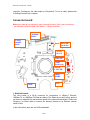
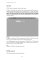
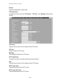
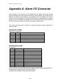
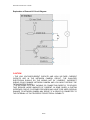
Network Camera User’s Guide
Appendix A: Alarm I/O Connector
Some features of the Camera can be activated by the external sensor that senses
physical changes in the area Camera is monitoring. These changes can include intrusion
detection or certain physical change in the monitored area. For examples, the external
sensor can be a door switch or an infrared motion detector. These devices are customer
provided, and are available from dealers who carry surveillance and security products.
Electrically, they must be able to provide a momentary contact closure.
This Camera provides wires for general I/O terminal interface as below (depends on
connector type):
Connector cable:
Cable for I/O connectors:
Name Number
Function
12VDC
1
DC 12V (50mA maximum)
DI
2
Digital signal input
GND
3
GND
DO
4
Digital signal output
485+
5
RS485 data +
4856
RS485 data -
Connector board:
Pin definition:
Pin
Name
1
12VDC in
2
MIC in3
MIC in+
4
Audio out+
5
Audio out6
Video out
7
12VDC out
8
DI
9
GND
10
DO
11
RS485+
12
RS485-
Function
DC 12V power input
External MIC inputExternal MIC input+
Composited video output
DC 12V output (50mA maximum)
Digital signal input
Digital ground
Digital signal output
RS485 data +
RS485 data -
User can refer to the schematic below to make a proper connection between I/O
connector and external sensor and output device.
connector and external sensor and output device.
85/99