1
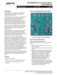
DETECTIVE
INSTRUCTION MANUAL
Crowcon Detection Instruments Limited
2 Blacklands Way
Abingdon Business Park
Abingdon
Oxfordshire
0X14 1DY
ENGLAND
Tel: +44 (0)1235 553057
Fax: +44 (0)1235 553062
Part No. M07096
Issue 4
7/03
CONTENTS
OPERATING GUIDE
3
GENERAL DESCRIPTION
4
OPERATION
Switch on
Display
Alarms
Overrange
Backlight
Clock
Switching off
Linking together
4
4
4
4
4
5
5
5
SETTING UP
Calibration menu
Off mode
Display mode
Alarm mode
Zero
Calibrate
5
5
5
6
6
6
BATTERY CHARGING
7
TERMINAL INTERFACE
7
TROUBLE SHOOTING GUIDE
9
MAINTENANCE & CALIBRATION
Recalibrating
Replacing sensor module
Replacing battery pack
10
10
10
11
LIMITATIONS TO USE
11
ACCESSORIES
11
SPARES
12
APPENDIX
Data logging
Alternative terminal interface
Alternative sounder selection
Leg assembly instructions
Certification information
13
13
13
14
14
16
Print Data
M07096
Issue 4
7/03
6
2
QUICK OPERATING GUIDE
TURN ON
Press ON, alarm sequence will be tested, then display either the gas levels or ‘MONITORING’.
ALARM
Alarm sounds (warbling tone) and the red LEDs flash, the hazardous gas symbol will flash or
the display will read ‘GAS HAZARD EVACUATE AREA’
RESET ALARM
Press the unmarked button.
BACKLIGHT
Press the button with the light symbol. It will stay on for 30 minutes unless the button is repressed.
LOW BATTERY
A continuous tone is heard.
TURN OFF
Press the ON and unmarked buttons together.
BATTERY CHARGING
Plug charging lead into the socket on the backplate and then plug into mains. Recharge time is
6-8 hours.
GENERAL DESCRIPTION
M07096
Issue 4
7/03
3
The Crowcon Detective is a transportable gas detecting unit capable of monitoring up to four
gases simultaneously, and provide warning of hazardous levels.
For small area monitoring, while personnel are working a single unit can be used. For protecting
a larger area a number of Detectives can be linked together, providing a protective barrier
around the work site.
The main body of the unit is made from fire retardent, high impact, UV stabilised ABS plastic
and is protected against water and dust ingress to 1P66. The unit is mounted on an epoxy
painted steel tripod frame which maximises stability. The frame encircles the unit to add further
protection, therefore making it ideal for the most hostile areas.
The sensors are located underneath the body of the unit for protection and a calibration
aspirator can be attached for spot sampling. The sealed lead acid batteries provide enough
capacity for 24 hours monitoring and half an hour in alarm mode.
When not in use Detective units can be conveniently stacked one on top of the other, or the
legs can be removed to minimise longer term storage space. See diagram at back of manual for
leg assembly instructions.
OPERATION
To SWITCH ON, press the ON button. The instrument will display a ‘TESTING ALARM’
message and indicate the battery voltage. If this is less than 6.4V the batteries may need
recharging. The red LEDs will sequence and the sounder operate. After 5 seconds the display
will change to display the gas levels.
DISPLAY
This is dependant on the type of sensors installed. For each sensor the display indicates the
gas concentration, units of measurement and the gas name.
The green power LED will flash intermittently to reassure the user that all is well.
ALARMS
When the Detective detects gas above a dangerous level, the red LEDs on top of the unit flash
in quick succession and the sounder emits a fast warbling noise. The channel responsible for
the alarm flashes on the display. Alarms may be reset by pressing the unmarked button once
the gas hazard has passed.
OVERRANGE
If a sensor is out of range, it causes the relevant information on the display to flash, indicating a
high gas level or a faulty sensor module. Calibration should then be checked.
BACKLIGHT
This can be activated to illuminate the display be pressing the button marked with the light
symbol. It will remain on for 30 seconds unless the button is re-pressed. The backlight will be
activated automatically if a gas alarm condition is reached.
CLOCK
This can be displayed by pressing the unmarked button. The display shows the time and the
M07096
Issue 4
7/03
4
elapsed time since the instrument was switched on. Pressing the button again, or waiting for
5 seconds returns the display.
SWITCHING OFF
This is done by pressing the ON and unmarked button together, provided the off function is not
disabled. This prevents accidental switching off of the instrument.
LINKING TOGETHER
Several Detectives can be connected together via the two four pin DIN sockets located on the
back of the instrument. These, and the computer interface socket, are protected to 1P66.
A ten metre long linking cable is supplied with the Detective and other lengths are available on
request.
To connect together, undo the cover on one of the 2 sockets, connect one end of the cable to
one Detective, and the other end of the cable to the next Detective in the chain. Either of the
two sockets can be used. Detectives can be linked in a chain or a continuous loop.
When one Detective goes into alarm it sends all the other Detectives into audible and visual
alarm via the linking cables. The Detective which has initiated the alarm can be identified by its
own LEDs rotating at a faster speed than the others. The red alarm LED on the front panel will
only flash on the unit which has seen gas. If another unit detects gas, it too will flash its front
panel LED and rotate its LEDs faster.
SETTING UP
To access the SET UP menu, it is necessary to know the instrument’s password. Unless this
has been changed by the user (see Terminal Interface), the password is 1,2,3,4 where the left
hand button is 1 and the right hand button is 4. After pressing CAL you have 5 seconds to enter
the password.
Within the SET UP menu the top line displays the option whilst the lower line defines the key
functions of the buttons below.
YES accepts the option
NO moves to the next option
QUIT returns to the previous level
There are 6 options:
OFF MODE
This enables the off to be either ENabled or DiSabled, making it impossible for unauthorised
personnel to switch the instrument off.
DISPLAY MODE
This enables the display to be set to
M07096
Issue 4
7/03
5
NORMAL: gas measuring
PEAK HOLD: gas levels on display are held at peak values as soon as alarm thresholds are
exceeded. Pressing the unmarked button will update the display to the current value if the alarm
is reset.
TWA: time weighted average readout on toxic channels
OFF: the display will only indicate ‘MONITORING’ or ‘GAS HAZARD EVACUATE AREA’
ALARM MODE
This enables the instrument to be set to acknowledge different toxic alarm types.
INSTantaneous sets the instrument to alarm as soon as a threshold toxic gas level is reached.
TWA causes the instrument to ignore temporary excursions above the instantaneous
thresholds, but go into alarm when the SHORT TERM or LONG TERM exposure levels are
reached.
ALL ACTIVE enables both TWA and INSTantaneous alarm types.
ZERO ALL
This should only be done when the instrument is in fresh air and a steady output is achieved.
On successful zeroing, there is an option to END the set up and return to measuring, or to
CONTinue with the set up.
CALIBRATE
Before this can be done the instrument should be zeroed. You will need a Detective aspirator
and a supply of Crowcon test gas.
Scroll through the available gas channels and press YES to calibrate the desired channel.
Aspirate gas over the sensors at Y2 litre/minute, when the reading is stable, press the UP and
DOWN options until the reading matches the concentration of the test gas, and then press
YES.
On successful calibration there is an option to END and return to measuring or to CONTinue
with the set up. Should a CAL FAILED message appear either the gas concentration was not
equal to the value set, and calibration should be repeated, or the sensor has deteriorated.
PRINT DATA
Ensure that the instrument is connected to a printer ready to receive XONIXOFF serial data via
the four pin connector on the back of the instrument marked, COMPUTER INTERFACE. A full
LOG-STATS (see TERMINAL INTERFACE) listing will now be downloaded to the printer.
BATTERY CHARGING
M07096
Issue 4
7/03
6
The built-in battery pack has sufficient capacity to power the instrument for 24 hours monitoring
and half an hour in alarm mode.
The Detective has a built in two stage charging circuit enabling the instrument to be left on
charge indefinitely. The red LED indicates that the instrument is on fast charge and the green
LED that it is on trickle charge.
To recharge the instrument locate the charging socket on the back of the Detective and undo
the cover. Connect the charging lead between the mains and the Detective. One of the two
LEDs will illuminate indicating the charge rate.
The charging lead is supplied for connection to either 110 or 240V, although the Detective must
be factory set to the expected voltage. Connect brown-live, blue-neutral, green/yellow-earth.
WARNING: THE INSTRUMENT MUST NOT BE CHARGED IN A HAZARDOUS AREA.
TERMINAL INTERFACE
This section describes how a computer may be used to reconfigure the instrument for a
particular application.
An IBM compatible PC or Psion Organiser with an R5232 port can be connected to the
Detective via its serial port and the four pin interface socket, located at the back of the
Detective (see appendix if not using an IBM compatible PC).
Note: the RS 232 port can only be used when the Detective is plugged into the mains
power supply.
Crowcon recommend the use of CROWCOMMS software for easy interfacing between a PC
and the Detective. The Detective must be switched on for successful communication and
plugged into a mains power socket via the battery charging lead. If the communication link is
working properly, keyboard entries are echoed back on the screen and the prompt
TPL<software version> appears after <return> or <enter> has been pressed.
Type help <return> to list the available functions.
HELP
CLOCK.
PASSWORD
SHORT-TIME
CAL-DUE
CONFIDENCE
ZERO
CALIBRATE
CHANNEL-INFO
LOG-CLEAR *
LOG-PERIOD *
LOG-STATS *
M07096
Issue 4
7/03
...this function
...read or set the clock
...set password
...read or set S.T.E.L. calc. period
...read or set date for next calibration
...enable or disable confidence tick
...zero one or all channels
...calibrate gas channel
...set channel variables
...clear logger memory
...read or set logging interval
...statistical display of logged data
7
LOG-DUMP *
...download of logger readings
LOG-LATEST *
...download of recent logger readings
TWA-REPORT
...read eight hour TWA levels
TWA-RESET
...reset eight hour TWA levels
READ
...read gas channel
SERIAL-NO
... read or set serial number
* See DATA LOGGING for the use of these commands.
Type HELP followed by one of these commands to discover its usage.
ZERO
Zero all channels. Do this BEFORE calibrating
CALIBRATE [chanl[value]Set a specified channel to read a given value. Aspirate known TEST
GAS over the sensors, once the sensor has stabilised press <return>
These functions are only available when using the terminal interface.
ZERO Echan]
Set a specific channel to zero.
CLOCK [hour][min][sec][day][month][year]
Set or read the real time clock.
PASSWORD [n1][n2][n3][n4]
Used to set a new password for restricting access to
the CALIBRATION MENU. Each of the 4 numbers
must be between I and 4 and a space should be
inserted between each of the numbers
SHORT-TIME [mins]
Sets the Short Term Exposure Limit which may be set
between 5 and 15 mins. 15 mins is the UK standard.
CAL DUE [day][month][year]
Sets the date after which a ‘CALIBRATION DUE’
message will appear at switch on.
CHANNEL-INFO [chani] To alter the configuration of FACTORY PRE-SET
sensor modules. The following prompts are given.
Sensor NAME>
Sensor UNITS>
FALLING ALARM threshold>
RISING ALARM threshold>
SHORT TERM exposure limit>
LONG TERM exposure limit>
Mid Span>
1 oxy, 0 other>
1 toxic, 0 other>
0, 1 or 2 decimal places>
Existing sensor information by be edited or accepted.
NOTE: Certain alarm types are inappropriate for certain sensors and should be disabled be
setting unrealistic levels. SHORT and LONG TERM limits may be set to 1 for flammable and
oxygen channels, as they are deactivated within the software. Mid span is a sensor specific
M07096
Issue 4
7/03
8
constant used by the processor to control calibration. Use default factory values at the end of
section.
For channels other than oxygen, there is the option to define the number of decimal places, the
extra decimal places are only relevant on low range measurements.
TWA-REPORT
TWA-RESET
READ[chan]
A glance view of the LONG TERM exposure levels.
Resets the LONG and SHORT TERM exposure levels.
View current gas level of specific channel.
MID SPAN values
Oxygen
Methane
Hydrogen Sulphide
Carbon Monoxide
Chlorine
Pentane
O2
CH4
H2S
CO
CL2
PEN
0.37
2.0
0.8
6.5
0.1
4.0
SERIAL-NO [nnnnnn]Enables the factory setting of the serial number into non-volatile RAM. If
this is corrupted the default number 0 is loaded, in this case the serial
number may be reprogrammed, otherwise only viewing is permitted.
TROUBLE SHOOTING GUIDE
SYMPTOM
DIAGNOSIS
REMEDY/CHECK
Does not switch on
battery flat
recharge battery
Does not switch off
OFF DISabled
alter configuration
Alarm signals, no gas
alarm latched
press unmarked button
Gas reading, no gas
zero drifted
zero instrument in fresh air
Unstable/inaccurate
reading
sensor failed
recalibrate/replace sensor
Alarm warbles but LEDs
on top are off
battery low
recharge battery
MAINTENANCE AND CALIBRATION
M07096
Issue 4
7/03
9
Crowcon recommend monthly gas response checks and a recalibration every 6 months.
Flammable sensors will respond to hydrogen and most hydrocarbons, but will only be calibrated
for a specific gas.
RECALIBRATING
This may be done using the ‘CALIBRATE?’ option in the setting up or by the CALIBRATE
function in the TERMINAL INTERFACE.
Zero the instrument in fresh air.
Locate the aspirator flowhead under the ledge below the sensors, underneath the instrument,
and secure with the two half turn fasteners.
Starting with the flammable gases, then moving onto toxic, connect the cylinder of test gas to
the inlet of the flow head via a flow meter. The direction of flow is marked on the flowhead.
Adjust the flowmeter to achieve a flowrate of ½ litre/minute.
Wait until the reading has stabilised on the display before programming in the new level.
Shut off the supply and disconnect the test gas.
Aspirate fresh air through the flowhead using the rubber bulb until the reading has returned to
zero.
REPLACING A SENSOR MODULE
Carefully remove the black lamp cover retainer, and remove the lens cover.
Using the box spanner provided, remove the 13m8 nut, and carefully lift off the top half of the
case.
Remove the 6pm molex JP9 labelled LAMPS connecting the LEDs to the main board.
Remove the 5 pin molex JP3 labelled BATT connecting the battery to the main board.
Identify the sensor module to be replaced and disconnect the flexible pcb from it by lifting the
shroud from the header and gently pulling on the tail.
Remove the two Pozi-drive screws and the old sensor module.
Remove the old gasket/membrane assembly.
Fit the new components according to a reverse of the above, ensuring that the shroud is
pushed home over the header to grip the flexible pcb tail securely. Replace the LED lead onto
the main board connected JP5.
Replace the battery lead onto the main board connector JP3.
Replace the top half of the case, and tightly screw the 1 3m8 nut back in place.
Replace the lens and the lamp cover retainer.
M07096
Issue 4
7/03
10
Detective sensor modules are supplied precalibrated from the Crowcon factory and will identify
themselves to the instrument when it is switched on. It is advisable to check the response to
test gas to ensure that no damage has occurred in transit and that installation has been carried
out successfully.
REPLACING BATTERY PACK
Carefully remove the black retaining screw and the lamp cover. Using the box spanner
provided, remove the 13MB nut, and carefully remove the top half of the case. Remove the 6
pin molex JP5 labelled LAMPS, enabling the top half of the case to be fully removed.
Disconnect all the molex connectors to the main board. Remove the four pozi drive screws
holding the metal base plate down.
Carefully lift off the board and metal plate. Remove the old batteries and replace with new
ones.
Replace the metal base and main board and screw back in place the four pozi drive screws.
Replace the molex connectors.
Replace the top half of the case, tightly screw the 13MB nut back in place.
Replace the lens and lamp cover retainer.
If any further maintenance is required, contact the Crowcon Service Department.
LIMITATIONS TO USE
LONG TERM STORAGE LIMITS
OPERATING LIMITS
MIN
MAX
MIN
MAX
0
20
-10
50
PRESSURE/mB
900
1100
900
3000
HUMIDITY/%RH
15
90
0
90
TEMPERATURE/C
ACCESSORIES FOR DETECTIVE
Aspirator probe (1 metre)
Extra aspirator hose (2 metre length)
Computer interface lead
Crowcomms Software for computer terminal emulation
M07096
Issue 4
7/03
C01297
M04032
E07394
C01715
11
SPARES
Main pcb
Moulding set
Frame assembly
Membrane switch label
IP65 sounder
LED cluster
Lamp cover
Sensor plate seal
Interface socket
Computer I/F socket
Charging socket
Inter-connecting lead, 10 metres
MB lock nut
Lamp cover retainer
Battery pack
Interconnection lead adaptor
S01326
M04385/6
M0I 461
E01468
E01160
E01456
M04289
M04290
E07392
E07393
E07391
E07397
M03624
M04315
C01406
E07413
Sensor assemblies:
o - 100 % LEL methane/flammable
o - 100 % Vol methane/flammable
0 - 50 ppm hydrogen sulphide
o - 500 ppm carbon monoxide
0- 10 ppm sulphur dioxide
0- 5 ppm chlorine
0- 10 ppm nitrogen dioxide
0- 100 ppm nitric oxide
0- 10 ppm hydrogen cloride
o - 25 ppm hydrogen cyanide
0 -25 % oxygen
S011375
S01423
S0l240
S01727
S01242
S01829
S01244
S01245
S01724
S01725
S01248
It is not recommended that sensor assemblies are stored for longer than 6 months prior to
use.
APPENDIX
M07096
Issue 4
7/03
12
DATA LOGGING
The integral data logger enables accurate historical record keeping of a individual’s exposure to
hazardous gas. Data logging takes place continuously while the instrument is switched on and
readings stored for each channel, at a rate set by LOG-PERIOD. For each channel the
maximum level seen that period is recorded. The logged data is kept in battery backed memory
when the instrument is switched off. When the memory is full, new data will overwrite the oldest
data, therefore it is a good idea to LOG-CLEAR the memory after inspecting it. Inspection is
done using LOG-STATS, LOG-DUMP and LOG-LATEST. Data is filed away in reports, (starting
at report 0), which may be displayed individually. A report is ended each time the instrument is
switched off, or it’s memory is inspected. The serial number is displayed at the beginning of
data reports.
Configuration of the data logger and access to logged data is via the following TERMINAL
INTERFACE commands:
LOG-CLEAR
Clears the data logging memory
LOG-PERIOD [hour][min][secs]
Displays or changes the data logging interval from
anywhere between 1 second and 24 hours.
NOTE the logger can store up to 24000 measurements, therefore on a 4 channel instrument
6000 measurements per channel. For most applications a LOG-PERIOD of 1 minute provides
a good compromise between duration and resolution, storing 100 hours of data.
LOG-STATS [report]
Shows the mm, mean, max values of all logged
data reports, or single report.
LOG-DUMP [report]
Outputs all the logged data by report, or a single
report. Every reading is outputted to the terminal
screen.
LOG-LATEST [hour][min][sec]
Dumps all data reports logged over the past 30
minutes or requested time period.
All command lines shown in square brackets are optional, if omitted then all reports are
outputted or default values used.
NOTE Logged data is formatted and displayed according to current instrument calibration and
therefore should be cleared prior to recalibration or sensor alteration.
ALTERATIVE TERMINAL INTERFACE
If terminal interface other than an IBM compatible PC or Psion Organiser is used it must be to
the following specification.
Capable of emulating a terminal VT52NTIOO mode
BAUD rate 2400, B data bits, 2 stop bits, no parity.
ALTERNATIVE SOUNDER SELECTION
M07096
Issue 4
7/03
13
Detective may be fitted with either a Banshee (grey) sounder or a MEDC (red) sounder,
dependent on when it was produced. The MEDC sounder has selectable tone patterns which
are determined by rocker switch position settings. To access these switches separate the
sounder from its base by twisting the body.
The sounder is preset to give an alarm tone of sweeping 2400-2850Hz at 7Hz with a typical
sound output of 114dBA, and a low battery alarm continuous tone at 2850Hz with a typical
sound output of 116dBA.
Other tones may be set according to the following table.
Factory set alarm tone - No. 5
No.
Tones
2nd
Tone
Code
Description
Typical
dBA
1
Alt tones 800/970 at ¼ sec
14
11111
2
Sweeping 800/970 at 7Hz
14
11110
Fast sweep
105
3
Sweeping 800/970 at 1Hz
14
11101
Medium sweep
105
4
Continuous 2850
14
11100
5
Sweeping 2400/2850 at 7Hz
4
11011
6
Sweeping 2400/2850
4
11010
7
Slow whoop
14
11001
Slow whoop
103
8
Sweeping 1200/500 at 1Hz
14
11000
Din Tone
103
9
Alt tones 2400/2850 at 2Hz
4
10111
10
Int tone 970 at 1Hz
14
10110
11
Alt tones 800/970 at 7/8Hz
14
10101
12
Int tone 2830 at 1Hz
4
10100
13
970Hz at ¼sec on I sec off
14
10011
102
14
Continuous 970Hz
14
10011
107
15
554Hz for I QOms & 440Hz for
400ms
14
10001
French fire sound
97
16
Int 660Hz ISOms on ISOms off
14
1000
Swedish fire alarm
97
17
lnt66OHz 1.8s on lBs off
14
01111
Swedish fire alarm
91
18
Int 660Hz 6.5s on 13s off
14
01110
Swedish fire alarm
90
M07096
Issue 4
7/03
104
116
Fast sweep
114
113
113
Back-up alarm (LF)
106
105
Back-up alarm (HF)
116
14
19
Continuous 660Hz
14
01101
Swedish fire alarm
90
21
Int 660 at 7/8Hz
14
01011
Swedish fire alarm
87
22
In 2850 150ms on 100ms off
14
01010
Pelican crossing
113
23
Sweep 800/970 at 50Hz
14
01001
Low frequency buzz
105
24
Sweep 2400/2850 at 50Hz
4
01000
High frequency buzz
112
NOTE:
The second sound is the low battery alarm.
In order to change the sounder tones, gently turn the bottom half of the sounder until it can be
removed, taking great care not to damage the wiring.
Locate the set of 5 switches and set to the required combination.
Replace the bottom half of the sounder and the labels.
Test the unit by switching ON.
M07096
Issue 4
7/03
15
CERTIFICATION INFORMATION
M07096
Issue 4
7/03
16
M07096
Issue 4
7/03
17
M07096
Issue 4
7/03
18
M07096
Issue 4
7/03
19
M07096
Issue 4
7/03
20
M07096
Issue 4
7/03
21