1
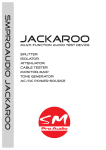
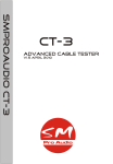
M-Patch 2
Operating Manual
August 2012
SAFETY INSTRUCTIONS
CAUTION: To reduce the risk of electrical shock, do not remove the cover or rear
panel of this unit. No user serviceable parts inside. Please refer servicing to qualified
personnel only.
WARNING: To reduce the risk of fire or electrical shock do not expose this appliance
to rain or moisture.
DETAILED SAFETY INSTRUCTIONS:
All safety and operation instructions of this manual should be read and adhered to
before operation.
Retain Instructions:
Please retain all safety and operating instructions for future reference.
Follow instructions:
All operation and user instructions should be followed.
Water, liquid and Moisture:
The appliance should not be used near water, rain or other liquids. Make sure that
no liquid can leak, spill or otherwise seep into the appliance.
Ventilation:
Please place the appliance so no obstacles interfere or impede the flow of air through
the ventilation openings.
Heat:
The appliance should be situated away from other heat sources such as heaters,
radiators, ovens, or other appliances that produce heat.
Power Source:
Make sure your appliance is set to the correct voltage for the country in which it will
be use before switching the device ON.
Grounding and Polarization:
Precautions should be taken so that the grounding or polarization means of an appliance is not defeated.
Power-Cord Protection:
Power supply cords should be routed so that they are not likely to be walked on,
pinched, damaged, worn, or rubbed by any other device or obstacle.
Cleaning:
The appliance should be cleaned only with a light soft cloth. Do not use any damaging or corrosive products on the unit.
Periods of inactivity:
The power cord of the appliance should be unplugged from the outlet when left unused for a long period of time or in case a lightning storm occurs.
Damage Requiring Service:
The appliance should be serviced by qualified service personnel when:
• The power supply cord or the plug has been damaged; or
• Objects have fallen, or liquid has been spilled into the appliance; or
• The appliance has been exposed to rain; or
• The appliance does not appear to operate normally or exhibits a marked change
in performance; or
• The appliance has been dropped, or the enclosure damaged.
Servicing:
The user should not attempt to service the appliance beyond that is described in the
Operating Instructions.
All other servicing should be referred to qualified service personnel.
2
FOREWORD
Dear Customer,
Thank you very much for expressing your confidence in SM ProAudio products by
purchasing this unit. The M-Patch 2 has been designed to be used as a standard
tool for home/pro studios, P.A. rental companies, Schools and in many other situations where audio products would be used. With much experience in the audio
industry over a long period of time, and along with valuable suggestions from our
customers, our engineers have developed a product we know you will be satisfied
with. We guarantee you uncompromising quality as well as excellent technical and
audio properties at an extremely affordable price.
Regards,
SM ProAudio
It should be pointed out, that extreme output volumes may damage your
ears and/or your headphone units. Turn down the LEVEL controls before you
switch on the unit.
PLACEMENT
The SM ProAudio M-Patch 2 has an electronic circuit inside as well as isolation
transformers. Be sure that there is enough air space around the unit for cooling.
As to avoid overheating, please do not place the units on high temperature devices
such as power amplifiers or near other units which may have high frequency transmittance such as wireless devices.
Mains voltage
The M-Patch 2 can be used with voltages ranging from 100V AC to 250V AC, please
make sure that you have selected the correct voltage range on the supplied power
supply before switching the unit ON. Any damage occurring as a result of incorrect
voltage selection may not be granted a warranty repair.
3
M-Patch 2 Main Features
Professional, multi-purpose passive volume attenuator with built in headphone
amplifier.
•
•
•
•
•
•
•
•
•
•
•
High quality ‚passive volume‘ attenuator
Great monitor switching device
2 x Input channels, 2 x Output channels
Combo, RCA, & 3.5mm input connectors
XLR outputs(balanced or unbalanced depends on the inputs selected)
Mono/Stereo summing switch
System mute function
Built in headphone amplifier
Quality components and rugged construction
Desktop or Rack-mountable installation
External 16Vac power supply (Supplied. Only required for operation of headphone amplifier)
1. INTRODUCTION
In purchasing the new M-Patch 2, you have acquired a passive volume control device of high class that meets the demands of the home/pro studio.
An affordable high-quality problem solver for mixer-less DAW and nonlinear video
production environments, the M-Patch 2 provides an ideal desktop stereo level control solution for any monitoring or distributed sound application.
The M-Patch 2 is essentially a multi-channel stereo attenuator using passive circuitry designed for users wishing to work without outboard mixers or bit-degrading
digital volume attenuators. The M-Patch 2 provides stereo level control solutions
for any monitor or distributed sound application. Featuring two rotary controls for
precise two x stereo channel level adjustments, and housed in a compact desktop
or rack-mountable sized chassis, the M-Patch 2 passive volume control and patch
control device is perfectly suited to serve in any common capacity in which more
control over volume is desired. From desktop media suites, mixer-less DAW and
MIDI systems, professional multi-channel installations, distributed sound systems,
or any other audio and video post production environments, the M-Patch 2 adds high
quality zone and/or channel control wherever it‘s needed.
2. THE DESIGN CONCEPT
2.1 High quality components and design
The philosophy behind SM ProAudio products guarantees a no-compromise circuit
design and employs the best choice of components.
2.2 Inputs and outputs
All inputs and outputs are secured firmly to the exterior chassis housing. This ensures robust quality and confidence in performance under all conditions.
4
3. Installation
Your SM Pro Audio M-Patch 2 was carefully packed in the factory and the packaging
was designed to protect the unit from rough handling. Nevertheless, we recommend
that you carefully examine the packaging and its contents for any signs of physical
damage, which may have occurred in transit.
If the unit is damaged, please do not return it to us, but notify your dealer and the
shipping company immediately, otherwise claims for damage or replacement may
not be granted. Shipping claims must be made by the consignee.
3.1 Desktop or Rack-mount installation
The SM Pro Audio M-Patch 2‘s compact size enables it to sit comfortably on your
desktop. We also include a versatile pair of rack/stand mounting ears which enable
both desktop stand mounting and standard 19” professional rack-mountable support
options.
Desktop mount configuration
For desktop angled mounting simply connect the included rack/stand mounting ears
in an upright manner to each side of the M-Patch 2 using the included screws.
Multiple screw positions are available on each side of the M-patch 2 which allow a
user defined selection of up to six (6) different angled positions. Screw the included
rubber feet/stoppers onto the bottom of the rack ears as to provide stability to the
M-Patch 2 in addition to protecting your desktop.
* Note: Please take into consideration your particular setup and cable arrangement
when deciding on mounting your M-Patch with the highest degree of angle in relation to your desktop surface. You will need to ensure that you have enough space to
connect your cables!
Rack-mount configuration
5
If you would like to rack-mount the M-Patch 2, simply connect the supplied rack/
stand ears to each side of the M-Patch 2 using the included screws. This allows
you to rack-mount the unit in a standard 19” professional rack.
4. Connections
The M-Patch 2 features two (2) separate input channels named “Aux” & “Stereo”.
The connections are found on the rear panel.
(Input section on rear panel of M-Patch 2).
* Note: The M-Patch 2 accepts mic or line level input signals. Do not connect your
power amplifier outputs to the M-Patch 2 inputs!
4.1 Stereo Inputs
The Stereo main inputs feature XLR bal/unbalanced combo connectors for L&R
input signal. This input is perfect for connection to your main audio interface device
(example; MBox 2, etc). Simply connect your cables directly to the unit with either
XLR or º” TS/TRS cables.
4.2 Aux Inputs
The Aux input channel features two different connection possibilities in the form of
2 x RCA (L&R) and a stereo 3.5mm mini-jack input. These connections are perfect
for devices such as a CD players line output or a 3.5mm stereo mini-jack connection
from your PC‘s standard soundcard.
* Note: You can connect up to three different devices to the three physical connector
possibilities simultaneously. The input selector on the front panel allows selection of
the desired input!
6
4.3 Analog Audio Outputs
The M-Patch 2 features two (2) pairs (L&R) of XLR balanced analog output connectors on the rear panel. These are labeled “1” & “2”.
Connect these outputs to your destination device (active monitors, digital recorder,
or wherever you need the attenuated output signal sent).
* Note: It is possible to activate or deactivate each desired output pair via the ‚output selector switches‘ on the front panel. It is possible to have both 1&2 outputs
active at the same time. This is very useful when connecting the outputs to a recording device and a monitoring device simultaneously!
4.4 Power Connection
Power to the M-Patch 2 is required only if you wish to use the headphone amplifier, or view the illuminated led indicator lamps.
The included power supply can be connected from mains power to the
power connector socket located on the rear panel of the M-Patch 2.
The Blue led on the front panel (next to the mono/stereo control switch) will illuminate when the external power supply is connected and mains power is present.
* Note: All passive attenuation functions operate fully without the connection of the
power supply. This enables full portable use of the M-Patch 2 without restriction.
7
5. FRONT PANEL CONTROLS
5.1 Stereo/Aux input selection control
The input selection controls on the front panel of the M-Patch 2 allow
selection of either ‚Stereo‘ or ‚Aux‘ input source material to be routed
to the output pairs for immediate listening and attenuation control.
Select the “stereo” position to activate the main stereo input source connected to
the XLR/combo inputs, or select “Aux” position to activate the RCA and 3.5mm
stereo mini-jack input source.
5.2 1&2 Output selector switch
The 1/2 output switch on the front panel of the M-Patch 2 is for selecting which desired output pair (1 +/or 2) you would like to route the
audio signal to.
Simply change the position of the switch to toggle between output destinations.
* Note: If you have more than one pair of monitor speakers you could create a
perfect switching facility for toggling between near-field and lager format active
room monitors.
5.3 Input volume rotary attenuator controls
The Aux input volume rotary attenuator control on the front panel of the M-Patch 2
adjusts the level of monitored output signal for devices connected to the Aux inputs
(either the RCA or 3.5mm stereo min-jack) of the M-Patch 2.
The stereo input volume attenuator switch on the front panel of the M-Patch 2 adjusts the level of monitored output signal for devices connected to the stereo inputs
(XLR combo connectors) of the M-Patch 2.
8
5.4 On/Off Mute Switch
The on/off mute switch on the front panel is for enabling and disabling the MPatch 2‘s built in mute function. All audio signal output is disabled when the
mute switch is in a depressed position.
The mute led will illuminate when the system is in a current muted state of operation.
5.5 Mono/Stereo Summing Switch
The mono/stereo summing switch on the front panel of the M-Patch 2 allows you to sum a stereo signal to a mono signal. This can be very handy
when testing your audio for certain issues like phase cancellation, preparation for AM radio, etc.
Select the desired mode of operation by positioning the mono/stereo switch in the
up or down position.
5.6 Headphone amplifier and output connector
A headphone amplifier is provided for monitoring the audio signal selected by the
‚Input Selection‘ control switches.
Simply connect a pair of headphones to the 1/4” TRS headphone connector socket
and use the rotary headphone volume control knob to adjust the volume level to
your desired setting.
* Note: Use of the headphone amplifier requires the connection of the external
power supply.
9
6. APPLICATION
6.1 Using the M-Patch 2
You can use M-Patch 2 anywhere you want to trim the amount of
gain; ie, reduce the volume of analog audio signals. For example,
you could use one to trim the output of a microphone pre-amplifier.
With its high-quality potentiometer,
the M-Patch 2 passes signal more
accurately, and sounds better than
most built-in volume controls. Another use might be to trim the levels
of a 5.1 or greater multi-channel
monitor system -- either one pair
of channels, or two, or all of them.
You can also use the M-Patch 2 to
How to connect the M-Patch 2
trim the output level of a Digital to
Analog Converter like those found
in high end pre-amplifiers. It is also useful as a local volume control for distributed
audio systems. The possibilities are endless!
Handy applications...
The M-Patch 2 is great for those times when you prefer to monitor directly from the
outs on your sound card or audio interfaces main outputs directly to your monitors.
When your monitors are on they are normally extremely loud. As a result, you may
become a bit frustrated as the volume is often simply too high to be comfortable.
Your only choice is to hook up through an external mixer and attenuate the signal or
to attenuate the signal in the computer outputs, thereby degrading your bit-levels.
Neither solution is completely satisfying. Mixers add color to the signal and reducing
the digital output in the computer will compromise the fidelity of your audio.
Simple steps for your home workstation...
1. Typically you should connect the output of your soundcard or audio interface to
the input of the M-Patch 2 using RCA, TRS or XLR jacks. You could also connect
multiple connections at the same time if required. For example, connect the outputs
of your audio interface (eg. Digidesign MBox 2) to the balanced combo connectors,
and your soundcards mini-jack output to the stereo 3.5mm AUX input on the MPatch 2. You could also connect your CD or other line level device to the AUX RCA
inputs. This enables you to level balance two input sources by passive attenuation!
2. Connect XLR cables from the outputs of the M-Patch 2 to your active monitors or
the amplifier that powers the monitors. Remember you have two (2) output destinations so if you have two different monitor pairs (near-field & far field (room speakers))
you can connect one pair to output 1 (L&R), and the other pair to output 2 (L&R).
3. Turn the volume all the way up on your monitors or amplifier, set your software &
software volume control panel to Zero dB, and use the M-Patch 2 on your desktop
to control your monitor level.
Simple, effective, transparent!
10
7. SPECIFICATIONS
AUDIO INPUTS
Connectors AUDIO OUTPUTS
Output Connectors HEADPHONE OUTPUT
Output Connectors Frequency response
Maximum output level
POWER
External PHYSICAL
Dimensions Net weight • 2 x XLR Combo connectors
• 1 x stereo RCA pair (L&R)
• 1 x stereo 3.5mm jack
• 2 x XLR output pairs (A-/L&R, B-/L&R)
• 1 x 14” TRS stereo output
• 20Hz - 20Hz +/- 0.5dB
• 320mW into 32Ω
• DC12-16V adaptor
• 22cm x 12cm x 8.6 cm
• approx. 1 kg
8. Warranty
8.1 Warranty Card
To be protected by this warranty, the buyer must complete and return the enclosed warranty card (signed/stamped by retail dealer) within 14 days of the date of
purchase to SM Pro Audio (see address below 3). Failure to return the card in due
time (date as per postmark) will void any extended warranty claims.
8.2 Warranty
8.2.1. SM ProAudio warrants the mechanical and electronic components of this
product to be free of defects in material and workmanship for a period of one (3)
years from the original date of purchase, in accordance with the warranty regulations described below. If any defects occur within the specified warranty period that
are not caused by normal wear or inappropriate use, SM Pro Audio shall, at its sole
discretion, either repair or replace the product.
8.2.2. If the warranty claim proves to be justified, the product will be returned
freight prepaid by SM Pro Audio within Australia. Outside of Australia, the product
will be returned at the buyer‘s expense.
8.2.3. Warranty claims other than those indicated above are expressly excluded.
8.3 Return Authorization Number
8.3.1. To obtain warranty service, the buyer must call SM Pro Audio during normal
business hours BEFORE returning the product (Tel.: +61 3 9555 8081). All inquiries must be accompanied by a description of the problem. SM ProAudio will then
issue a return authorization number or by email to [email protected]
8.3.2. The product must be returned in its original shipping carton, together with the
return authorization number, to the following address:
SM Pro Audio
Service Department
W25, 26-28 Roberna St
Moorabbin
Melbourne, Victoria
Australia 3189
11
8.4 Warranty Regulations
8.4.1. Warranty services will be furnished only if the product is accompanied by an
original retail dealer‘s invoice. Any product deemed eligible for repair or replacement by SM Pro Audio under the terms of this warranty will be repaired or replaced
in the best possible manner.
8.4.2. If the product needs to be modified or adapted in order to comply with
applicable technical or safety standards on a national or local level, in any country
which is not the country for which the product was originally developed and manufactured, this modification/adaptation shall not be considered a defect in materials
or workmanship.
The warranty does not cover any such modification/adaptation, irrespective of
whether it was carried out properly or not. Under the terms of this warranty, SM Pro
Audio shall not be held responsible for any cost resulting from such a modification/
adaptation.
8.4.3. Free inspections, maintenance/repair work and replacement of parts are
expressly excluded from this warranty, in particular if caused by inappropriate use.
Likewise, the warranty does not cover defects of expendable parts caused by
normal wear of the product. Expendable parts are typically pots, potentiometers,
switches and similar components.
8.4.4. Damages/defects caused by the following conditions are not covered by this
warranty:
• Misuse, neglect or failure to operate the unit in compliance with the instructions given in the user or service manuals.
• Connection or operation of the unit in any way that does not comply with the technical or safety regulations applicable in the country where the product is used.
• Damages/defects that are caused by any other condition beyond the control of
SM Pro Audio.
8.4.5. Any repair carried out by unauthorized personnel will void the warranty.
8.4.6. Products which do not meet the terms of this warranty will be repaired
exclusively at the buyer‘s expense. SM Pro Audio will inform the buyer of any such
circumstance. If the buyer fails to submit a written repair order within 4 weeks after
notification, SM Pro Audio will return the unit C.O.D. with a separate invoice for
freight and packing. Such cost will also be invoiced separately when the buyer has
sent in a written repair order.
8.5 Claim for Damages
Failure of SM Pro Audio to provide proper warranty service shall not entitle the
buyer to claim (consequential) damages. In no event shall the liability of SM Pro
Audio exceed the invoiced value of the product.
8.6 Other Warranty Rights
This warranty does not exclude or limit the buyer‘s statutory rights provided by
national law, in particular, any such rights against the seller that arise from a legally
effective purchase contract.
The information contained in this manual is subject to change without notice. No
part of this manual may be reproduced or transmitted in any form or by any means,
electronic or mechanical, including photocopying and recording of any kind, for any
purpose, without the express written permission of SM Pro Audio.
ALL RIGHTS RESERVED © 2012 SM Pro Audio
SM Pro Audio Service Department
W25, 26-28 Roberna St Moorabbin Melbourne, Victoria Australia 3189
12