1
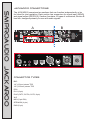
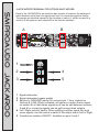
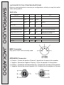
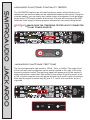
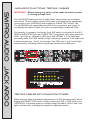
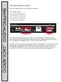
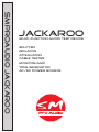
SMPROAUDIO JACKAROO JACKAROO Multi-function Audio Test Device Splitter isolator attenuator cable tester monitor/amp Tone generator ac/dc power source SAFETY INSTRUCTIONS SMPROAUDIO JACKAROO CAUTION: To reduce the risk of electrical shock, do not remove the cover or rear panel of this unit. No user serviceable parts inside. Please refer servicing to qualified personnel only. WARNING: To reduce the risk of fire or electrical shock, do not expose this appliance to rain or moisture. DETAILED SAFETY INSTRUCTIONS: All safety and operation instructions of this manual should be read and adhered to before operation. Retain Instructions: Please retain all safety and operating instructions for future reference. Follow Instructions: All operation and user instructions should be followed. Water, Liquid and Moisture: The appliance should not be used near water, rain or other liquids. Make sure that no liquid can leak, spill or otherwise seep into the appliance. Ventilation: Please place the appliance so no obstacles interfere or impede the flow of air through the ventilation openings. Heat: The appliance should be situated away from other heat sources such as heaters, radiators, ovens, or other appliances that produce heat. Power Source: Make sure your appliance is set to the correct voltage for the country in which it will be used. Grounding and Polarization: Precautions should be taken so that the grounding or polarization means of an appliance is not defeated. Power-Cord Protection: Power supply cords should be routed so that they are not likely to be walked on, pinched, damaged, worn, or rubbed by any other device or obstacle. Cleaning: The appliance should be cleaned only with a light soft cloth. Do not use any damaging or corrosive products on the unit. Periods of Inactivity: The power cord of the appliance should be unplugged from the outlet when left unused for a long period of time. Damage Requiring Service: The appliance should be serviced by qualified service personnel when: - The power supply cord or the plug has been damaged; or - Objects have fallen, or liquid has been spilled into the appliance; or - The appliance has been exposed to rain; or - The appliance does not appear to operate normally or exhibits a marked change in performance; or - The appliance has been dropped, or the enclosure damaged. Servicing: The user should not attempt to service the appliance beyond what is described in the Operating Instructions. ALL OTHER SERVICING SHOULD BE REFERRED TO QUALIFIED SERVICE PERSONNEL FOReWORD SMPROAUDIO JACKAROO Dear Customer, Thank you very much for expressing your confidence in SM Pro Audio products by purchasing this unit. The JACKAROO was designed to be a comprehensive “workhorse” test device for home, project, and professional studios, live sound rental companies, repair centers, schools, and fixed installations—in short, virtually any and all venues where audio products are used. Drawing on years of hands-on experience in the audio industry and valuable suggestions from our customers, our engineers have developed a product that we are certain will more than meet your expectations. As with all SM Pro Audio equipment, the JACKAROO was designed to provide you with superb performance, excellent technical specifications, and uncompromised audio quality at an extremely affordable price. Regards, SM ProAudio INSTALLATION Your SM Pro Audio JACKAROO was carefully packed at the factory and the packaging is designed to protect the unit from rough handling. Nevertheless, we recommend that you carefully examine the packaging and its contents for any signs of physical damage that may have occurred in transit. If the unit is damaged, please do not return it to us, but notify your dealer and the shipping company immediately, otherwise claims for damage or replacement may not be granted. Shipping claims must be made by the consignee. PLACEMENT The SM Pro Audio JACKAROO utilizes an electronic circuit. Be sure that there is enough air space around the unit for cooling. To avoid overheating, please do not place the unit on high temperature devices such as power amplifiers or near other units that may have high frequency transmittance, such as wireless devices. Mains voltage The JACKAROO can be used with voltages ranging from 100V AC to 250V AC. Please make sure that you have selected the correct voltage range on the back of the unit and that the required fuse setting is correct as well before switching the unit ON. Damage occurring as a result of incorrect voltage selection may not be covered as a warranty repair. INTRODUCTION SMPROAUDIO JACKAROO The JACKAROO is a combination cable tester, signal generator, splitter, combiner, “gender-bender,” and more. Think of it as an audio “Aussie Army Knife”—an indispensible tool for studios, PA companies, repair shops, fixed installations, touring bands, sound contractors...you get the idea. Packaged in a sturdy 2U rack-mount format, the JACKAROO features a wide assortment of front-panel inputs and outputs, including Neutrik XLR, 1/4" TRS, 1/8" TRS, RCA, 5-Pin MIDI, BNC, RJ11, and RJ45. Any input can feed any output, making it easy to test cables, split signals among multiple devices, separate left/right stereo signals, and connect equipment with dissimilar I/O configurations. Transformer-isolation, on-board continuously-variable passive attenuators with true switched bypass, and banana plug connections for continuity testing are also included. You can even monitor the signal with the included amplifier and speaker on the Jackaroo. (Yes, we really did try to think of everything!) Hardware DESIGN As with all SM Pro Audio products, the JACKAROO features a no-compromise circuit design and only the highest quality hardware components. For enhanced durability, all inputs and outputs are secured firmly to the exterior chassis. Great attention has been paid to the overall construction and design to ensure years of robust performance under a variety of performance conditions. connectors 2 x XLR Male 2 x XLR Female 2 x DMX 5-Pin 2 x Speakon 4 x 1/4" TRS 4 x 1/8" (3.5mm) TRS 4 x RCA 2 x 5-Pin DIN/MIDI 2 x BNC 2 x RJ11 2 x RJ45 2 x Rotary Signal Attenuators AC/DC Voltage Generator (5VDC, 12VDC, 9VAC, 17VAC) @ 500milliamp Banana Plug Continuity Tester Signal Generator w/ 100Hz / 1kHz / 10kHz Tones Monitor Speaker (each of the 8 lines being tested can be selected) Ground Lift Switch Transformer-Isolation Switch Left / Right Selection Switch (for splitting stereo to mono signals) JACKAROO Connections A 5K 0 1/8” TRS RJ11 RCA B RJ45 XLR 48V PHANTOM POWER 1 2 3 4 5 6 7 GND LIFT TR BNC 1/4” TRS RCA RJ11 RJ45 12V dc Off 100hz 1k 10k XLR ATT PASS L-R LINK TR 1/8” TRS RCA RJ11 Connector types BNC 1/4" (6.5mm) stereo TRS 1/8" (3.25mm) stereo TRS RCA RJ11 (6-pin) RJ45 (CAT5, CAT5e, CAT6, 8-pin) XLR MIDI (5-pin DIN) SPEAKON (4-pin) DMX (5-pin) RJ45 XLR 4 17V ac 5 6 7 3 JACKA ROO 8 2 Off Voltage selector Monitor selector MONITOR SPEAKER XLR BNC 1/4” TRS 1/4” TRS 9V ac Voltage out Max 500mA Bananas: Continuity tester With Beeper & LED MIDI RCA 0 5V dc Test Tone WARNING: DO NOT ENGAGE CABLE TEST WITH POWER RUNNING THRU THE TEST CABLES! 1/8” TRS 1/8” TRS Attenuator 8 Cable Test L-R XLR ATT 5K BNC Attenuator ATT PASS MIDI RECEIVE 1/4” TRS ATT SEND SMPROAUDIO JACKAROO The JACKAROO comprises two sections that can function independently or be for linked for joint operation. Each section has connectors for signal input (SEND) and signal output (RECEIVE). Section A contains 10 types of connectors; Section B has four, designed primarily for use with audio signals. MIDI 1/8” TRS RCA 1/4” TRS JACKAROO SIGNAL ROUTING AND LEVEL 1/4” TRS ATT 5K B 0 1/8” TRS RJ11 RCA RJ45 XLR 48V PHANTO M PO WER 1 2 3 4 5 6 7 BNC GND LIFT RCA RJ11 RJ45 XLR 12V dc Off 1/4” TRS 9V ac ATT PASS L-R LINK TR 4 17V ac Voltage out Max 500mA Bananas: Continuity tester With Beeper & LED MIDI RCA 0 5V dc Test Tone WARNING: DO NOT ENGAGE CABLE TEST WITH POWER RUNNING THRU THE TEST CABLES! 1/8” TRS 1/8” TRS Attenuator 100hz 1k 10k TR 1/4” TRS XLR ATT 8 Cable Test L-R MIDI 5K BNC Attenuator ATT PASS RECEIVE A SEND SMPROAUDIO JACKAROO Each of the JACKAROO’s two sections has a panel of controls, the settings of which determine the level of a signal and how it is routed through the device. The panels are identical except for the function of switch 3, which in panel A is used to lift the ground, and in panel B to link the two sections. 5 6 7 3 JACKAR OO 8 2 Off Voltage selector Monitor selector MONITOR SPEAKER XLR 1/8” TRS RCA 1/4” TRS ATT 1 5K 0 Attenuator 2 3 ATT PASS L-R GND LIFT TR 4 5 1 Signal attenuator 2 Signal attenuator bypass switch 3 Section A: GROUND (earth) lift; removes pin 1 from connection Section B: LINK; When activated, all inputs on section A are copied on section B, so that stereo signals on A can be split between sections A and B, or incoming signals can be split among three outputs. 4 Left / Right selector switch. When splitting a stereo signal into dual mono signals, use this switch to select if the output side is Left or Right. 5 Transformer isolation ON/OFF. Available on pins 2 and 3. JACKAROO PIN CONfigurations SMPROAUDIO JACKAROO Below is a general guide to common pin configurations, which you may find useful when testing cables. XLR 3-Pin Application 1 2 3 Notes Canford Talkback backbone earth/screen +24V DC audio D54 screen no connection analogue multiplex DMX screen data - data + High End Systems intelligent fixtures control ground data - data + Martin intelligent fixtures control (old) screen data + data - this is not the same as 3-pin DMX! Martin intelligent fixtures control (new) screen data - data + Martin have now changed to be pin compatible with 3-pin DMX screen signal + signal - common +15 VDC data this is not an official standard: see esp. Martin!!! Loudspeakers Martin smoke machine control Microphones (Europe standard) Microphones (US standard) Microplex MIDI Connector Only pins 4 and 5 are normally used. SPEAKON Connector 1+ Positive Carries the positive Channel 1 signal from the amp to the speaker 1- Negitive Carries the negative Channel 1 from the amplifier to the speaker 2+ Positive Carries the second positive (Ch. 2) signal from the amp to the speaker 2- Negative Carries the second negative (Ch. 2) signal from the speaker to the amp JACKAROO functions: continuity tester 1/8î TRS RJ11 RCA 5K 0 RJ45 XLR 48V PHANTOM POWER 1 2 3 4 5 6 7 GND LIFT TR BNC 1/4î TRS RJ11 RCA 12V dc 5V dc Test Tone RJ45 XLR 1/4î TRS 9V ac ATT PASS L-R LINK TR 5 4 17V ac O ff Voltage out Max 500mA Bananas: Continuity tester W ith Beeper & LE D MIDI RCA 0 100hz 1k 10k WARNING: DO NOT ENGAGE CABLE TEST WITH POW ER RUNNING THRU THE TEST CABLES! 1/8î TRS 1/8î TRS Attenuator 8 Cable Test L-R XLR ATT 5K BNC Attenuator ATT PASS MIDI SEND 1/4î TRS ATT RECEIVE IMPORTANT: MAKE SURE THE ITEM BEING TESTED IS NOT CONNECTED TO ANY POWER SOURCE! 6 7 3 JACKAROO 8 2 Off Voltage selector Monitor selector MONITOR SPEAKER XLR 1/8î TRS RCA 1/4î TRS Bananas: Continuity tester With Beeper & LED JACKAROO FUNCTIONS: Test tone 1/4î TRS 1/8î TRS 5K 0 RJ45 RJ11 RCA ATT XLR 48V PHANTOM POWER 1 2 3 4 5 6 7 GND LIFT TR BNC 1/4î TRS XLR RCA RJ11 12V dc 5V dc Test Tone RJ45 XLR 100hz 1k 10k ATT PASS L-R LINK TR 4 17V ac Voltage out Max 500mA Bananas: Continuity tester W ith B eeper & LED MIDI 1/4î TRS 9V ac O ff 100hz 1k 10k Test Tone RCA 0 Attenuator WARNING: DO NOT ENGAGE CABLE TEST WITH POWER RUNNING THRU THE TEST CABLES! 1/8î TRS 1/8î TRS ATT 8 Cable Test L-R MIDI 5K BNC Attenuator ATT PASS RECEIVE The tone test generator can be set to 100Hz, 1kHz, or 10kHz. The output level of the test tone can be adjusted via the screw located to the right of the tone frequency selector switch.The test tone signal will appear only at the section A output connectors unless the LINK switch (in the section B control panel) is set to ON, in which case the tone will appear at both the A and B output connectors. Note that the signal is carried only by pins 2, 3, and 4 of a connector, as pin 1 is ground. SEND SMPROAUDIO JACKAROO The JACKAROO features an on-board continuity tester, which allows you to determine if an electrical path can be established between two points. Using the included cables, you can easily test a wide variety of equipment, such as lamps, single wires, PCB circuit boards, and the like. A buzzer will sound and the LED illuminate if the signal is flowing properly between the two points being tested. 5 6 7 3 JACKAROO 8 2 Off Voltage selector Monitor selector MONITOR SPEAKER XLR 1/8î TRS volume RCA 1/4î TRS jackaroo functions: TESTING CABLES The JACKAROO features a built-in cable tester that performs an automated test routine. To test a cable, connect both sides of the cable to the appropriate connectors on the JACKAROO and engage the CABLE TEST switch. The The JACKAROO will sequentially test each of the connectors’ pins (up to 8), and display the status of each pin on the correspondingly-numbered LEDs. 1/4” TRS ATT 5K 0 1/8” TRS RJ11 RCA RJ45 XLR 48V PHANTOM POWER 1 2 3 4 5 6 7 GND LIFT TR BNC 1/4” TRS RCA RJ11 1/8” TRS 12V dc 5V dc RJ45 Off 100hz 1k 10k MIDI 1/4” TRS 9V ac ATT PASS L-R LINK TR 5 4 17V ac Voltage out Max 500mA Bananas: Continuity tester With Beeper & LED XLR RCA 0 Attenuator Test Tone WARNING: DO NOT ENGAGE CABLE TEST WITH POWER RUNNING THRU THE TEST CABLES! 1/8” TRS XLR ATT 8 Cable Test L-R MIDI 5K BNC Attenuator ATT PASS RECEIVE For example, if a properly functioning 3-pin XLR cable is connected to the XLR SEND and RECEIVE jacks and CABLE TEST is engaged, both upper and lower LEDs 1 will light up, followed by LED pair 2 and LED pair 3. If the cable was incorrectly wired, the LEDs would not light, indicating a problem. If the cable had a short between pins 1 and 2, for example, then LED pairs 1 and 2 would light simultaneously, indicating that the signal was shorted across both pins. SEND SMPROAUDIO JACKAROO IMPORTANT: Before testing any cables, please make sure that no power is running through them. 6 7 3 JACKAROO 8 2 Off Voltage selector Monitor selector MONITOR SPEAKER XLR 1/8” TRS RCA 1/4” TRS 48V PHANTOM POWER 1 2 3 4 5 6 7 8 Cable Test WARNING: DO NOT ENGAGE CABLE TEST WITH POWER RUNNING THRU THE TEST CABLES! TESTING CABLES with phantom power When testing a cable to determine the presence of 48V phantom power, do not engage the CABLE TEST switch. Simply connect the XLR or TRS cable to the JACKAROO; if phantom power is running through the cable, LEDs 2 and 3 will light simultaneuosly, indicating the presence of phantom power. jackaroo functions: AC/DC power supply Voltages are selected on the JACKAROO front panel. Available voltages are 5VDC, 12VDC, 9VAC, and 17VAC. The connector is a 2.1mm DC jack, center positive. 5K 0 RJ11 RCA RJ45 XLR 48V PHANTO M PO WER 1 2 3 4 5 6 7 GND LIFT TR BNC 1/4” TRS RJ11 RCA RJ45 12V dc 1/4” TRS 9V ac ATT PASS L-R MIDI LINK TR 6 7 3 Voltage out Max 500mA Bananas: Continuity tester With Beeper & LED 5 4 17V ac Off 100hz 1k 10k XLR RCA 0 5V dc Test Tone WARNING: DO NOT ENGAGE CABLE TEST WITH POWER RUNNING THRU THE TEST CABLES! 1/8” TRS 1/8” TRS Attenuator 8 Cable Test L-R XLR ATT 5K BNC Attenuator ATT PASS MIDI RECEIVE 1/8” TRS JACKAR OO 8 2 Off Voltage selector Monitor selector MONITOR SPEAKER SEND 1/4” TRS ATT XLR 1/8” TRS RCA 1/4” TRS 12 5V dc Off Voltage out Max 500mA V dc 9V ac 17V ac Voltage selector jackaroo functions: Monitor amp and speaker 1/4” TRS ATT 5K 0 1/8” TRS RJ11 RCA RJ45 XLR 48V PHANTO M PO WER 1 2 3 4 5 6 7 BNC GND LIFT RCA RJ11 RJ45 12V dc Off MIDI 4 3 5 6 7 8 2 Off Monitor selector 1/4” TRS 9V ac ATT PASS L-R LINK TR 4 17V ac Voltage out Max 500mA Bananas: Continuity tester With Beeper & LED XLR RCA 0 5V dc Test Tone WARNING: DO NOT ENGAGE CABLE TEST WITH POWER RUNNING THRU THE TEST CABLES! 1/8” TRS 1/8” TRS Attenuator 100hz 1k 10k TR 1/4” TRS XLR ATT 8 Cable Test L-R MIDI 5K BNC Attenuator ATT PASS RECEIVE The JACKAROO has a built in amplifier and speaker that can be used to monitor audio signals on pins 2 - 8. (Pin 1 cannot be monitored as it is always ground.) The speaker output volume level can be adjusted via the slotted knob located just below the monitor selector knob. SEND SMPROAUDIO JACKAROO The JACKAROO can supply four different voltages to various devices, such as effects units, that require external power. Note that the maximum current the JACKAROO can supply is 500ma (milliamps); connecting devices that exceed this specification may damage the unit. 5 6 7 3 JACKAROO 8 2 Off Voltage selector Monitor selector MONITOR SPEAKER XLR 1/8” TRS RCA 1/4” TRS JACKAROO FUNCTIONS: SPLITTING signals Splitting a stereo signal into dual mono signals In this example we’ll take stereo 1/4" TRS cable and split the signal into two mono RCA outputs. A 5K 0 1/8” TRS RJ11 RCA RJ45 XLR 48V PHANTO M PO WER 1 2 3 4 5 6 7 BNC GND LIFT RJ11 RCA 12V dc RJ45 XLR ATT PASS L-R LINK TR 4 17V ac Off Voltage out Max 500mA Bananas: Continuity tester With Beeper & LED MIDI 1/4” TRS 9V ac 5V dc Test Tone WARNING: DO NOT ENGAGE CABLE TEST WITH POWER RUNNING THRU THE TEST CABLES! 1/8” TRS RCA 0 Attenuator 100hz 1k 10k TR 1/4” TRS 1/8” TRS 8 Cable Test L-R XLR ATT 5K BNC Attenuator ATT PASS MIDI RECEIVE 1/4” TRS ATT B SEND SMPROAUDIO JACKAROO The JACKAROO lets you easily split signals, change connector gender, perform attentuation, and more. 5 6 7 3 2 JACKAR OO 8 Off Voltage selector Monitor selector MONITOR SPEAKER XLR 1/8” TRS RCA 1/4” TRS 1. Make sure that the CABLE TEST switch is NOT engaged 2. Connect the 1/4" TRS stereo source signal into the section A 1/4" input (lower left). 3. Connect an RCA cable to the section A RCA output (upper left) and a second cable to the section B RCA output (upper right). ATT 5K ATT 0 5K Attenuator 0 Attenuator B A ATT PASS L-R ATT PASS L-R GND LIFT TR LINK TR 4. Select LEFT using the L-R switch in the section A control panel. 5. Select RIGHT and set LINK to ON in the section B control panel. The signal will now be split. If the signal level is too high on one or both sides, switch ATT (attenuation) ON and use the rotary control(s) to attenuate the signal. If the signal needs to be transformer isolated, or the ground needs to be lifted to remove hum and noise, simply engage the GND LFT switch. By following the above example, you can split, attenuate, and combine signals, change the gender of connectors, and create a variety of input/output configurations. JACKROO REAR PANEL SMPROAUDIO JACKAROO The rear panel contains the following connectors: AC POWER INPUT 110V-240V selector switch 2 AC OUTPUT connectors 2 DC OUTPUT connectors 2 CAT5 LINK connectors Jackaroo WARNING: DO NOT ENGAGE CABLE TEST WITH POWER RUNNING THROUGH THE TEST CABLES! Rj45 PO WER SUPP LY Rj45 AC Power In Made in China AC 17V 0.5A AC 9V 0.5A DC 9V 0.5A DC 12V 0.5A LINK POWER INPUT A B A. Mirrors the front-panel power supply to provide power for external devices, such as effects pedals, effect units, other circuits, etc. Maximum current is 500ma. Four voltages are available: 5VDC, 12VDC, 9VAC, and 17VAC. B. RJ45 connectors for linking together multiple JACKAROOs. If you have several test rooms, or a studio and a recording room, you are able to connect several JACKAROOs together so that longer cable runs and different types of gear can be tested. The RJ45s 8-pins mirror the front-panel section A input signals. 1 WARRANTY CARD SMPROAUDIO JACKAROO To be protected by this warranty, the buyer must complete an online warranty registration within 14 days of the date of purchase on www.smproaudio.com. 2 WARRANTY 1. SM ProAudio warrants the mechanical and electronic components of this product to be free of defects in material and workmanship for a period of one years from the original date of purchase, in accordance with the warranty regulations described below. If any defects occur within the specified warranty period that are not caused by normal wear or inappropriate use, SM Pro Audio shall, at its sole discretion, either repair or replace the product. 2. If the warranty claim proves to be justified, the product will be returned freight prepaid by SM Pro Audio within Australia. Outside of Australia, the product will be returned at the buyer's expense. 3. Warranty claims other than those indicated above are expressly excluded. 3 RETURN AUTHORIZATION NUMBER 1. To obtain warranty service, the buyer must call SM Pro Audio during normal business hours BEFORE returning the product (Tel.: +61 3 9555 8081). All inquiries must be accompanied by a description of the problem. SM Pro Audio will then issue a return authorization number. Return authorizations may also be obtained by submitting a request to [email protected]. 2. The product must be returned in its original shipping carton, together with the return authorization number, to the following address: SM Pro Audio Service Department W25, 26-28 Roberna St Moorabbin Melbourne, Victoria Australia 3189 4 WARRANTY REGULATIONS SMPROAUDIO JACKAROO 1. Warranty services will be furnished only if the product is accompanied by an original retail dealer’s invoice. Any product deemed eligible for repair or replacement under the terms of this warranty will be repaired or replaced within 30 days of receipt of the product at SM Pro Audio. 2. If the product needs to be modified or adapted in order to comply with applicable technical or safety standards on a national or local level, in any country which is not the country for which the product was originally developed and manufactured, this modification/adaptation shall not be considered a defect in materials or workmanship. This warranty does not cover any such modification/adaptation, irrespective of whether it was carried out properly or not. Under the terms of this warranty, SM Pro Audio shall not be held responsible for any cost resulting from such a modification/adaptation. 3. Free inspections, maintenance/repair work and replacement of parts are expressly excluded from this warranty, in particular if caused by inappropriate use. Likewise, the warranty does not cover defects of expendable parts caused by normal wear of the product. Expendable parts are typically pots, potentiometers, switches, and similar components. 4. Damages/defects caused by the following conditions are not covered by this warranty: 0LVXVHQHJOHFWRUIDLOXUHWRRSHUDWHWKHXQLWLQFRPSOLDQFHZLWKWKHLQVWUXFWLRQVJLYHQLQ the user or service manuals . &RQQHFWLRQRURSHUDWLRQRIWKHXQLWLQDQ\ZD\WKDWGRHVQRWFRPSO\ZLWKWKHWHFKQLFDORU safety regulations applicable in the country where the product is used. 'DPDJHVGHIHFWVWKDWDUHFDXVHGE\DQ\RWKHUFRQGLWLRQEH\RQGWKHFRQWURORI603UR Audio. 5. Any repair carried out by unauthorized personnel will void the warranty. 6. Products that do not meet the terms of this warranty will be repaired exclusively at the buyer’s expense. SM Pro Audio will inform the buyer of any such circumstance. If the buyer fails to submit a written repair order within 4 weeks after notification, SM Pro Audio will UHWXUQWKHXQLW&2'ZLWKDVHSDUDWHLQYRLFHIRUIUHLJKWDQGSDFNLQJ6XFKFRVWZLOODOVR be invoiced separately when the buyer has sent in a written repair order. 5 CLAIM FOR DAMAGES Failure of SM Pro Audio to provide proper warranty service shall not entitle the buyer to claim (consequential) damages. In no event shall the liability of SM Pro Audio exceed the invoiced value of the product. 6 OTHER WARRANTY RIGHTS This warranty does not exclude or limit the buyer’s statutory rights provided by national law, in particular, any such rights against the seller that arise from a legally effective purchase contract. The information contained in this manual is subject to change without notice. No part of this manual may be reproduced or transmitted in any form or by any means, electronic or mechanical, including photocopying and recording of any kind, for any purpose, without the express written permission of SM Pro Audio. ALL RIGHTS RESERVED © 2010 SM Pro Audio SM Pro Audio Service Department W25, 26-28 Roberna St Moorabbin Melbourne, Victoria Australia 3189