1
United States Patent [191
[54-] ELECTRONIC GAME APPARATUS AND .
of PDP-l”; 1962, pp. 37-38.
Popular Electronics; “The First Motorola/AMI ‘6800’
MPU Computer Project”; Nov. 1975; pp. 33-37.
Primary Examiner-Richard C. Pinkham
Assistant Examiner-yVance Y. Hum
Attorney, Agent, or Firm-Phillips, Moore,
[76] Inventors: William F. Wilke, 702 N. Minnesota
St., Carson City, Nev. 89701; Alan G.
Hutcheson, 349 Smithridge, Reno,
Nev. 89502; Richard D. Ross, 285 E.
Lincoln Way, Sparks, Nev. 89431
[21] Appl. No.: 651,914
Weissenberger, Lempio & Majestic
[57]
ABSTRACT
Jan. 23, 1976
[22] Filed:
[5 1] Int. Cl.2 .............................................. .. A63F 9/00
[52] US. Cl. ............................. .. 273/94 R; 273/85 R;
An electronic apparatus for simulating athletic contests
is disclosed. A speci?c embodiment of the apparatus is
a football game including a simulated playing ?eld,
wherein the play execution and play outcome for each
play is displayed in real time. Two opposing players are
273/DIG. 28
Field of Search ........... .. 273/1 E, 85 R, 94, 54 C,
273/118 A, 119 A, 121 A, 122 A, 125 A, 126 A,
138 A, DIG. 28; 235/1 B, 92 GA, 156;
340/ 172.5, 323 R, 323 B, 337
[56]
References Cited
U.S. PATENT DOCUMENTS
2,614,840 10/ 1952 Monkres ......... ..
3,231,276
3,556,525
3,868,l 12
3,874,669
3,907,290
4,026,555
1/ 1966
l/ 1971
Cooper ..
Pegg ..
4/1975
2/ 1975
Ariano
Avera ......... ..
5/1977
9/ 1975
Kirschner
Fisher et a1.
et .....
a1. ................. .. 273/85 R
alternatively on defense or offense, according to stan
dard football rules. The game is automatic except for
the choosing of the play by the offensive player and the
choosing of a counteracting play strategy by the defen
sive player. Random numbers are generated automati
cally by the apparatus, and are applied to probability
tables to determine play results. A scoreboard keeps
track automatically of the time left in the game, the
score, the yards to go for a first down, etc. All aspects
of the game are controlled by a microprocessor and a
processor controller comprising a control program
stored in a read-only memory. The playing ?eld com
prises an array of lights that are selectively turned on by
OTHER PUBLICATIONS
the microprocessor to graphically show the play action.
Electronics; “Scamp Microprocessor Aims to Replace
Mechanical Logic”; Sep. 18, 1975; pp. 81-87.
I“ _ Q
nearer
..PUT I
SWITCHES
IBQJASTQZ
\
.
24 Claims, 15 Drawing Figures
*
“ _'— _ __ —_
I
I
DECODE
I
_
g
AI I5
INPUT GAT E
I
4s
RED TEAM
KEYBOARD
SWITCHES
I
J
{gig-Egg
(256 x a) s_s
ADDRESS BUS9
RoM MEMORY
\
I7
L
x. Y
X,|
a4
ENABLE
I
_
ADDRESS
( 8K X 8 l
Row
SELECT Rg
_-_
B 7 SE6. R4
L?l£c°?°'-_LER__ °fLI _I°L”_I
0P3
AND KEY BOARD LEDs
‘I
SCOREBOARD
5;;
2°
DISPLAY
—
_"
N1
_
64 53x5 um
N2
DRIVERS AND LATCHES
I2 7- SEGMENT
LED NuMERALs
IIIIHIHT
5
FIELD
l2
SELECE R5
LATCHE:
DRIVERS AND LATCHES FOR
SCOREBOARD MEssAeE INDICATORS
PLAYING
R]
DECODER
I
22' 24
_‘ _ ‘J
4a
r
OUTPUT
OH, OH 0,,
KEYBQARD
LED s
42
_
I 0P6 SELECT :
LATCHESx'7
I
YA
ig
(PROCESSOR CONTROLLER)
30
CLOCK
T?
I
g
2 PHASE
2 |
ENI ENZ CLR
4
—
32
-
RAM MEMORY
4._o
1" I
WE
I MEMORY
I BUS 94
SELECT DECODE __
D
,L
COIN
"w??gmgc?i? START DETIECTOR
PROCES/SOR BUS so
I6
__
c
_— w
“I m
‘any BIDIRECTIONAL
2x I
June 6, 1978
Decus Proceedings; “Spacewar: Real-Time Capability
METHOD
[53]
4,093,223
[11]
[45]
Wilke et al.
U.S.Patent
June 6, 1978
Sheet 2 of 11
4,093,223
I20 .
@
E
Mm5o01z>Eu
/
#IQ
\w3Ez2oL9l(.\5f_Ikrl
\\
\\
\
2 60
M4.mF03205
mIQE
w.
2300. E6
mIF .._.mEOm
um,
U.S.Patent
June 6, 1978
Sheet 6 of 11
4,093,223
( START )
(colN RECEIVED INTERRUPTTOL
was
I
WAIT
LOOP
CHECK COIN COUNT
AND, IF EQUIPPED;
UPDATE TOTALIZERS
_‘
HAS GAME ‘JUST
BEEN POWERED UP
RETAIN AND INDICATE
NoDISPLAY GAMIE
FROM PRIOR
HAVE ENOUGH COINS
c E
lA AR
BEEN ENTERED?
ND
\
START
I
ROUTINE
(FIRST HALF OR SECOND HALF?)§E§9?I-J——
&
FIRST
I
[RESET ALL INDICATORS AND RAMI
I
SAVE SCOREPSET SECOND
HALF INDICATOR- CLEAR ALL
OTHER REGISTERS AND RAM
Dr
I
DETERMINE WHO IS PRESENTLY ON
OFFENSE AND WHO IS ON DEFENSE
SCAN OFFENSE AND DEFENSE
SWITCHES FOR DETECTION OF
PLAY / PLAY STRATEGY SELECTION
‘
1
_
HAS OFFENSE SELECTED
KEYBOARD‘
HANDLER <
(PLAY
BEFORE SET TIME
LIMIT HAS PASSED?
ROUTINE
N
o
PENALTY - SUBTRACT
GOZPENSWQM
POSITION
YES
L_—, I
(P LAYHASSTRATEGY
DEFENSE BEFORE
SELECTEDSET )No a'AgFPgggggg'"
TIME LIMIT HAS PASSED
HEA‘ég-gE?gélNsT
E
is
_I
YES
(INVALID PLAY cHosEN?)-———No
SET l'INIVALID
PLAY"
I
INDICATOR ON
SCOREBOARD
k
RANDOM
I
NUMBER
READ PRESENT VALUE OF RANDOM NUMBER
Rgfr'll'NE
GENERATOR AND STORE OBTAINED VALUES IN RAM
FIG ._ 80
U.S.Patent .
June 6, 1978
4,093,223
Sheet 7 of 11
IS PLAY CHOSEN A KICKOFF, A
PUNT, OR A FIELD GOAL ATTEMPT?
YES
NO
I
COMPARE PLAY SELECTED BY OFFENSE
WITH PLAY STRATEGY SELECTED BY DEFENSE
HAS SAME
I
PLAY/ PLAY
YES _
STRATEGY BEEN SELECTED?
NO
I
ACCESS I'SAIT‘IE PLAY'I
SUCCESS CRITERION
PROBABILITY TABLES
AND DETERMINE PLAY
OUTCOME INCLUDING
YARDS GAINED OR LOST
(SEE FIG..9)
PLAY
OUTCOME
ROUTINE
II
I
HAS sAME PLAY CATEGORY
BEEN SELECTED?
YES
NO
ACCESS "SAME CATEGORY‘l
SUCCESS CRITERION
PROBABILITY TABLES
AND DETERMINE PLAY
OUTCOME INCLUDING
YARDS GAINED OR LOST
(SEE FIG-9)
I
ACCESS NDIFFERENT CATEGORY‘
SUCCESS CRITERION PROBABILITY
TABLES AND DETERMINE PLAY
OUTCOME INCLUDING YARDS
GAINED OR LOST (SEE FIG-9)
CALCULATE OFFENSIVE
FINAL FIELD POSITIONv
I
mess KICK lN FLIGHT YARDS
PROBABILTY TABLE AND IF A
KICKOFF- ALso DETERMINE
RuNBAcK YARDS
6»
FIG_8b
U. S .Patent
June 6, 1978
4,093,223
Sheet 8 of 11
3
I
SET INITIAL POSITIONS
OF DEFENDERS
DISPLAY IN REAL TIME ON
PLAYING FIELD LEDS THE
KICKOFF AIND RUN BACK,
OR PUN'I; OR FIELD
GOAL ATTEMPT
DISPLAY IN REAL TIME ON
PLAYING FIELD LED'S THE
OFFENSIVE PLAY AND DEFENSE
CONVERGENCE ON OFFENSE AT
PREDETERMINED FINAL FIELD
PLAY
EXECUTE
ROUTINE
'
POSITION
I
(WAS THE PASS INCOMPLETE YES
NO
RETURN BALL
TO ORIGIINAL LINE
OF SCRIMMAGE
I
r
I
r
-
ES
(HAS PASS BEEN INTE RCEPTED OR A FUMBLE ON A RUN?)-Y—_‘
NO
I
(HAS A TOUCHDOWN O R FIELD GOAL BEEN MAD
YES
@lr
l CALCULATE NEW DOWN]
I
UPDATE SCORE
AND POSITION
BALL FOR EXTRA POINT IF A T.D.
(ANY DOWI\S LEFT N
II
YES
ACCESS EXTRA POINT PROBABILITY
END
PLAY
ROUTINE
0
TABLE IF EXTRA POINT TRY,
CALCULATE AND DISPLAY RESULT
AND UPDATE SCORE
f
1
OFFENSE RETAINS
POSSESSION OF BALL
DEFENSE TAKES
POSSESSION OF BALL
I
CLEAR ALL OBSOLETE PLAY
DATA AND UPDATE ALL INDICATORS
Q-IAs TIME IN HALF OR IN GAME Ru'N oum?
.
NO
I RETURN FOR NEXT PLAY1
‘
IINDICATE
VOR FIRST GAME
HALF OVERI
OVER’
QB
_. FIG“. 8C
v
U.S.Patent
June 6, 1978
4,093,223
Sheet 9 of 11
I ENTER I
I
WAS PLAY SELECTED
A PASS OR A RUN?
PASS
ACCESS PROBABILITY
Y
TABLE’“ TO DETERMINE:
IS PASSER SACKED?
I NO
VARMBLE
ACCESS PROBABILITY
YES
ACCESS PROBABILITY
TABLE“ TO DETERMINE:
Is THERE A Loss ON
IS BALL INTERCEPTED?
INO
ACCESS PROBABILITY
TABLE!‘ TO DETERMINE
Is PAss INCOMPLETE?
*
X
N0
‘NO
ACCESS PROBABILITY
TABLE-1* To DETERWNE;
Is THE BALL FUMBLED'?
NO
YES
STORE
RESULT
IN RAM
<___I
ACCESS
PROBABILITY TABLE** I
D ETERMINE RANGE OF
STORE
RESULT
|N RAM
‘__....___.__J
YARDS BALL THROWN IN THE AIR
I
ACCESS PROBABILITY
TABLE’" TO DETERMINE
RANGE OF YARDS
GAINED‘ ON RUIN
ICONVERT ALGORITHM
|
L_—__
E
VARIABLE {
ACCESS PROBABILITY
TABLE‘" TO DETERMINE
RANGE OF YARDS
LOST ON RUN
CALCULATE ACTUAL
YARDS THROWN WITHIN
RANGE GIVEN
I
X
ACCESS PROBABILITY TABLE‘I‘
DETERMINE RANGE OF RUN ON
AFTER PASS CAUGHT
lcONvERT ALGORITHM l
'
CALCULATE ACTUAL
YARDS GAlNElD/LOST
ON RUN WIITHIN
RANGE GIVEN
[CONVERT ALGORITHm
.
E
I
.
VARIABLE
CALCULATE ACTUAL
YARDS GAINED WITHIN
RANGE GIVEN
I
X
ACCESS PROBABILITY TABLE‘"
VARIABLE
TO DETERMINE RANGE OF
TABLE
YARDS LOST ON SACK
ACCESS
I
CONVERT ALGORITHM
E
VARIABLE {
*NOTB THIS TABLE IS
DIFFERENT FOR EACH OF
THE THREE SUCCESS CRITERION.
*‘*NOTE= EACH PLAY CHOICE HAS
ITS OWN X VARIABLE ACCESSED
PROBABILITY TABLE FOR
DETERMINING YARDAGE GAINED
OR LOST ON THE PLAY.
YES
F
I
VARIABLE
TABLE
ACCESS
YES
THE RUN?
YES
TABLE " (TABLH TO DETERMINE
ACCESS
RUN
CALCULATE ACTUAL
YARDS LOST WITHIN
RANGE GIVEN
I RETURN )
FIG_9
U.S.Patent
4* 215W-
Y
RANDOM
NUMBER
VARIABLE
I
2
3
4
5
6
7
8
9
I0
II
I2
l3
I4
l5
l6
June 6, 1978
Sheet 10 of 11
4,093,223
PASSER SACKED
I_0ss ON RUN
cooms AS
PLAY CHOSEN
. PLAY CHOSEN
APPEARS IN
I
2
3
4
s
s
7
a
ROM
MEMORY
(OCTAL)
0000 I
000I
I
com I
con
l
0I00 l
mm 0
one 0
0III 0
I000 0
mm 0
mm 0
mu 0
II00 0
II0I 0
III0 0
IIII 0
l
I
I
I
I
0
0
0
0
0
0
0
0
0
0
0
I
I
I
I
I
0
0
0
0
0
0
0
0
0
0
0
l
I
I
I
I
0
0
0
0
0
0
0
0
0
o
0
l
I
I
0
0
I
l
0
o
I
II
I
l
I
I
I
I
I
0
0
l
I
0
0
I
I
I
I
I
l
I
I
I
I
0
0
I
0
0
0
I
I
I
I
l
I
I
I
l
l
0
0
0
0
0
0
0
0
0
0
I
I
I
377
377
577
360
360
l6
I4
0
0
l6
l6
l6
I6
l7
l7
I7
"' 10a
B'NARY
X
RANDOM
NUMBER
VARIABLE
4* EQUIV.
I 0000
2 com
a com
4 con
5 0I00
6 mm
7 mm
a mu
9 I000
I0 I00I
II mm
I2 mu
I3IIOO
I4 II0I
I5 III0
I6 IIII
YDS GAINED
l
0
I
0
I
0
l
I
I
I
I
0
0
o
0
0
0
2
|
0
I
0
I
0
0
o
0
o
I
I
I
0
0
0
a
0
0
0
0
0
0
0
0
0
0
0
o
0
I
I
0
coome AS
YDS LOST
4
0
0
0
0
0
0
0
0
0
0
0
0
o
o
0
l
s
0
0
0
0
0
0
0
0
0
0
0'
0
0
0
0
0
e
1
I
0
o
I
0
I
0
0
0
0
0 0
0
I
0. I
I
0
0
l.
0 0
0. 0
030
0 0
0
I
0
I
.Qgg?g?bg
a
0
0
0
I
l
I
0
0
0
0
I
I
I‘
I
0
0
(OCTAL)
I04
202
I02
20I
I0I
20I
202
202
204
202
IoI
I0I
IOI
4|
42
22
1
4,093,223
2
the probability tables, for determining play success pa
ELECTRONIC GAME APPARATUS AND METHOD
BACKGROUND OF THE INVENTION
rameters thereby. With this information, the game con
troller displays, automatically in real time, the actual
path of the play execution on the playing ?eld including
offensive and defensive formations. An array of light
emitting diodes is the playing ?eld display apparatus for
the present embodiment.
1. Field of the Invention
This invention relates to an electronic game that
simulates an athletic contest, and more particularly to -
an electronic game wherein all play action is automati
cally generated, with the offensive player and the de?n
Accordingly, it is an object of this invention to pro
sive player required only to choose from a plurality of 10 vide an apparatus, including a microprocessor and a
possible play strategies.
processor controller for electronically simulating an
2. Description of the Prior Art
Prior art electrical football games have required a
great deal of player effort and interaction. Placement of
players on the ?eld, keeping track of the score, the
numbers of downs played, yards to go for a ?rst down,
etc., have all been required to be performed by the
players themselves. The games have had various ran
domizing means for varying the results generated by a
given chosen play, but these means either comprise a 20
drum that is manually rotated or buttons that are pushed
to generate a play randomizing result. The more sophis
ticated of the games only provide sixteen different play
results for each chosen play. Furthermore, only the play
result is indicated, usually simply by lighting a single
light under a given play result indicator. No real-time
display of the actual execution of the play is provided.
Another limitation is that in most such games, the play
athletic contest.
Another object of this invention is to provide a game
wherein the players can use their skill and knowledge of
the sport to receive an advantage, and wherein also is
incorporated the element of luck, which is also basic to
the sport.
Another object of this invention is to provide a ran
dom sample procedure that insures that many results are
possible when the same strategy moves are made by
each player.
_
Another object of this invention is to provide a game
that is fully automatic, including the scoring of the
game, keeping track of the time left in the game, etc.,
and including the display on the playing ?eld, in real
time, of offensive and defensive movement, and the
movement of the game play, with the only action re
quired of the participants being the pressing of a button
ers must keep track of time left in the game. No auto
matic means for keeping time or for providing a penalty 30 prior to every play.
if either side delays the game are supplied.
A further object of this invention is to provide a game
SUMMARY OF THE INVENTION
The present invention provides apparatus for simulat
ing, in an accurate and realistic way, an athletic contest 35
on an electronic playing ?eld. Opposing players are
supplied a keyboard, with various plays selectable by
whereby all results are determined almost instantly, but
displayed in the same time frame as would be experi
enced in the actual athletic contest.
BRIEF DESCRIPTION. OF THE DRAWINGS
These and other objects and advantages of the pres~
the person presently on offense, and various play strate
ent invention will become more apparent upon refer
gies selectable by the person presently on defense, with
play results generated automatically based on probabili 40 ence to the following description and accompanying
drawings, in which:
ties corresponding to those representing the actual
sport, and based on random numbers generated by the
apparatus. The apparatus provides for an extensive
number of possible results for each play, the number
cording to the present invention;
chosen by the offensive player and the play strategies
keyboard with various play buttons thereon;
FIG. 1 is a perspective view of a football game, ac
FIG. 2 is a top plan view of the simulated playing
being almost equal to the number of possible results 45 field shown in FIG. 1;
experienced in the actual sport. Once the play has been
FIG. 3 illustrates a preferred embodiment of a player
chosen by the defensive player, all the rest of the calcu
lations, including the play outcome determination, the
play execution determination and the display of the play
execution is automatically performed. The apparatus
includes a game controller comprising a microprocessor
controlled by a processor controller permanently con
tained in a read-only memory, a random number gener
ator, and a plurality of probability tables, also stored in
a memory. Also included is a scoreboard which, under
the control of the game controller, automatically dis
plays the present game score, the game time remaining,
whether there exists a penalty for delay of game, and
FIG. 4 illustrates a preferred. embodiment of the
scoreboard of the present invention;
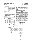
FIG. 5 is a block diagram of the electronic compo
nents of the present invention;
FIG. 6 is a block diagram and partial schematic of the
microprocessor and state decode unit shown in FIG. 5;
FIG. 7 is a partial schematic of the means for selec
tively actuating respective scoreboard and playing ?eld
lights;
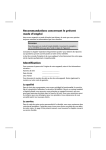
FIG. 8 is a ?ow diagram shown on 3 sheets 8a, 8b and
8c of the control program stored in the read-only mem
ory shown in FIG. 5;
FIG. 9 is a detailed partial ?ow diagram of the play
under the control of the game controller, are performed
outcome aspect of the ?ow diagram of FIG. 8;
in a time span that is short as compared with real time,
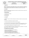
FIGS. 10a and 10b depict two typical probability
so that no delay in the game is detected therefrom by
tables of the present invention; and
the players. The computations include the obtaining of 65 FIGS. 11a and 11b detail the layout of a section of the
random numbers from the random number generator
light array on the playing ?eld, with FIG. 110 further
and the using of these numbers along with the play and
showing a typical run play as executed, and FIG. 11b
the play strategy chosen to access speci?c locations in
showing a typical pass play as executed.
other information required by the players.
The play outcome and execution computations,
3
4,093,223
4
ARE DEFENSE — CHOOSE YOUR PLAY” to indi
DESCRIPTION OF THE PREFERRED
cate the present game status of each player.
EMBODIMENT
FIG. 4 illustrates in detail the preferred embodiment
FIG. 1 illustrates an electronic football game appara
of the scoreboard 14 of the present invention. The
tus 10 according to the present invention. The game 10 5 scoreboard includes a plurality of seven-segment LED
includes a simulated playing ?eld 12, a scoreboard 14,
numeral indicators, such as at 26, for display of game
score, time left in the half, etc., and a plurality of game
and two player keyboards 16, 17 (one shown) placed on
messages that are individually illuminated from behind
each side of the playing ?eld 12. Also included is a
by incandescent lights (not shown). The messages are
conventional power supply 18 for converting an AC
silk-screened or otherwise added to the plastic surface
power source into the voltage levels needed for opera
of the scoreboard 14, making the scoreboard translucent
tion of the game 10 electronics.
thereby. The messages are generally self-explanatory
The simulated playing ?eld 12, shown more fully in
and re?ect standard football occurrences. “BLUE
FIG. 2, includes an array 20 of light-emitting diodes
TEAM SET” and “RED TEAM SET” messages light
(LED’s) mounted on a printed circuit board (not
shown) directly beneath the surface of the ?eld 12. The 15 up when the respective player has selected his play and
pressed the corresponding button. The “INVALID
array 20 is organized in ?ve rows of ?fty-three diodes
each for a total of two hundred sixty-?ve LED’s. On a
scale where the playing ?eld 12 simulates a ?eld of 100
yards from one goal line to the other goal line, each
light is spaced at two yard intervals down the length of
the ?eld, with a light at each end of every row posi
tioned two yards into the end zone. Having ?ve rows of
lights extending in parallel lengthwise on the ?eld per
mits play movement to be displayed both down the ?eld
12 and across the ?eld 12. Note that the number of rows
and lights in each row is arbitrarily determined and can
vary according to economic and space limitations. The
playing ?eld 12 surface is plastic, with the yard lines and
PLAY” message lights up if one of the players presses a
button that is inappropriate for the current game situa
tion, e.g. pressing a KICK-OFF button when a play
from scrimmage, such as a “SCREEN PASS”, is
needed. (The means for providing this check mecha
nism will be described in detail infra.) The “GOOD”
and “NO GOOD” messages indicate whether an at
tempted extra point or ?eld goal has been successful or
25 not.
The main electronic components of the football game
10 are shown in block diagram form in FIG. 5. A game
controller, indicated generally within dotted lines 30, is
the means by which every operation in the game 10 is
numerals added by silk-screening or an equivalent pro 30
controlled. Speci?cally, the controller 30 includes a
cess. The playing ?eld 12 is translucent so that the array
20 of LED’s is not visible unless an individual LED is
on and emitting light. The surface acts as a lens for the
microprocessor and state decode 32, a processor con
troller contained in a read-only memory (ROM) 34, a
random access memory (RAM) 36, a data input multi
point source LED’s, thus providing a planar light on the
plexer 44, and other components described further here
playing ?eld 12 surface that is visible at almost any 35 inafter. A ROM is used because the control program
angle of viewing. Note that all the LED’s used in the
acts as a permanent component of the game 10. No
present embodiment emit only red light, whether the
change in the control program is desired or possible
light is indicating offense or defensive movement. The
once the ROM 34 has been modi?ed to reflect the steps
LED array 20 functions to display to the game players
of the control program therein. The RAM 36 is needed
the path of the offensive play, i.e., the location and
as a scratch-pad memory to store values needed during
movement of the ball, and the location and movement
a given played game, e.g. to store the time left in the
of ?ve defensive players. To distinguish the two, the
game, where the ball currently is located on the playing
defensive player lights pulsate while the ball light ap
?eld 12 (i.e., which LED in array 20 is presently lit to
pears to be continuously lit. As will be explained herein
indicate the ball position), the number of downs remain
after, however, the ball light also pulsates at a rate that 45 ing, etc. All these values change from game to game,
is fast enough to normally be undiscernible to the
and within a given game. Further, many values change
human eye.
FIG. 3 illustrates in detail one of the two keyboards
during each given play.
16, 17 indicated in FIG. 1. The keyboards 16, 17 are
identical and include fourteen buttons or keys each, as
seen in FIG. 3. The keyboards 16, 17 are physically
tional processor bus 90. An address register 38, loaded
by the microprocessor 32 via the processor bus 90,
de?nes what storage location in each memory 34, 36 is
accessed by the microprocessor 32. The address register
38 performs this function by communicating the address
loaded by the microprocessor 32 to the memories 34, 36
arranged such that each player’s button choice is out of
the normal line of sight of the other player. The buttons
include “KICK-OFF”, “PUNT”, “EXTRA POINT”,
“FIELD GOAL”, and ten available line-of-scrimmage
plays common to an actual football game. On plays
from scrimmage, the offensive player presses a button
to choose his next play, and the defensive player tries to
Access to the ROM 34 and RAM 36 is via a bidirec
55 via an address bus 96. This address continues to appear
on the address bus 96, during an instruction fetch or
memory read/write, until a new address is loaded into
the address register 38 by the microprocessor 32.
Data is inputted to the microprocessor 32 by means of
what he thinks is the same button on his keyboard. If 60 the data input multiplexer (MUX) 44. The input MUX
anticipate the offensive player’s chosen play by pressing
any of the ?rst four buttons described above are pushed
by the offensive player, however, the defensive player
44 operates to selectively enable the passage of data that
is inputted to the MUX 44 on one of two buses to its
does not need to attempt a counteracting strategy. In
output bus, which in this case is the bidirectional pro
addition, to ensure that the players know who presently
cessor bus 90, or to block any output thereto. One of the
is on the offensive, i.e., who has “possession” of the 65 inputs to the input MUX 44 is a memory bus 94, which
game ball, an LED 22 or LED 24 on each keyboard 16,
contains data being outputted from a given addressed
17 will light up respectively next to “YOU HAVE
word in either the ROM 34 or RAM 36. Speci?cally, a
THE BALL — CHOOSE YOUR PLAY” or “YOU
given address on the address bus 96 addresses a single
4,093,223
memory word which may be in either the RAM 36 or
the ROM 34. Note that no address will access a memory
word in both memories at the same time. Thus, the
outputs of both memories 34, 36 can be connected to the
single memory bus 94. The addressing of a given word
in either memory causes the data stored at that memory
location to automatically be coupled to the memory bus
94, and thereby to the input MUX 44.
Data can also be written into the RAM 36 for tempo
rary storage therein. Once a desired address has been
loaded into address register 38 via processor bus 90, the
6
90. Time multiplexing of the processor bus 90, allows
control information, addresses, and data to be transmit
ted between the processor and external components on
this one bus, as described above.
The microprocessor 32 is controlled internally by an
instruction set of forty-eight instructions, including data
manipulation, binary arithmetic, and jump-to-subrou
tine instructions. Besides the use of the processor bus 90
for control, other devices may be controlled by the
microprocessor 32 with the use of the S0, S1, S2 and
SYNC output control lines generated by the INTEL
8008. In the present embodiment, the S0, S1, S2 and
bus 90 is again available for the microprocessor 32. The
microprocessor 32 couples data via this bus 90 to the
memory word in the RAM 36 identi?ed by the stored
address in register 38, to thereby store this data in that
addressed memory word location.
create the microprocessor 32 control signals of;output
enable (OE), keyboard switch input enable (IN), load
selectively accessed by the microprocessor 32 via the
48 (OUT).
SYNC lines are decoded in the state decoder 212 to
lower order address word into address register 38
The other bus connected to the input MUX 44 is the
(ENl), load higher order address into addresslegister
input data bus 92. This bus 92 couples selective informa
38 (BN2), enable writing of the RAM 36 (WE), and
tion from either the blue team keyboard switches 16 or
the red team keyboard switches 17. Switches 16, 17 are 20 enable output from the output enable address decoder
The various registers in the INTEL 8008 include the
input/output register 202, the arithmetic/logic unit 204,
mand storage register, and address bus 96. The address
which implements the addition, subtraction and logic
bus 96 data is decoded in an input gate select decode 46,
which acts thereby to select which of the switches 16, 25 operations called for by the instruction set, and the
accumulation, memory, and program counter registers
17 will be read into the microprocessor 32 via the input
206, which among other functions provides temporary
data bus 92 and the input MUX 44.
storage for data being operated on and for subroutine
Output display components, such as LED array 20
return addresses. The instruction decode and control
and scoreboard 14, are also accessed by the micro
processor 32 by means of the address register 38, again 30 unit 208 provides the logic for manipulating the regis
ters 202, 206 and the arithmetic unit 204 based on the
acting as a temporary command storage register. In this
type of instructions read in and decoded by the INTEL
case, part of the data resultant on address bus 96 is
decoded by an output enable address decoder 48 for
8008. The timing of the INTEL 8008 and thus the game
generating output enable commands 0P4) through 0P7
10 is regulated by a clock generator 210 that operates
which selectively enable one of the eight output blocks 35 from an external two-phase clock 42 (see FIG. 5). The
of game indicators (whether incandescent message indi
clock 42 is a digital circuit that outputs digital pulses at
address register 38, which acts as a temporary com
cators or LED’s). The rest of the data on the address
bus 96 is used to further select a given indicator within
a speci?c frequency. Normally, the time between pulses
is On the order of 10*6 seconds.
The coin detector 40 acts to start the microprocessor
the block chosen by the generated output command.
This subassembly will be described in greater detail 40 32 by setting a coin ?ip-?op 214 which enables the
below.
interrupt (INTR) ?ip-?op 216 to turn on at the next
The functioning of game 10 begins by the detection
proper clock time which in the present embodiment is at
by a coin detector 40 of the deposit of the requisite
time SYNC-(1J2. This clock time is generated by inverter
amount of money into the game. Note that a simple start
218 and AND gate 220. The output of the INTR ?ip
push-button would be just as easily usable for this func 45 ?op 216 is coupled to the INTR input of the INTEL
tion. The coin detector 40 communicates this game
8008, which thereby forces the INTEL 8008 to access
starting condition to the microprocessor 32. The micro
the ?rst location word in the ROM 34. For further
processor 32 is thereby forced to access a given word in
information on how the INTEL 8008 operates in this
the processor controller, i.e., in the control program,
regard, the INTEL 8008 User’s Manual, referred to
which enables the program to begin.
50 above, is incorporated by reference.
As shown in FIG. 6, the state decoder 212 takes the
The Microprocessor and State Decode.
S0, S1, S2, and SYNC outputs of the INTEL 8008 along
The main element of the game controller 30, and
with three lines (A12 — A15) from the address bus 96
therefore the game 10, is the microprocessor and state
and the SYNC~¢2 to generate the above-listed output
decode 32. This unit is shown in more detail in FIG. 6. 55 signals. The IN signal operates to select whether the
In conjunction with the processor controller stored in
input data bus 92 information or the memory bus 94
the ROM 34, the microprocessor and state decode 32 is
information is to pass through the input MUX 44. The
the main supervisor of all aspects of the operation of the
OE signal also is inputted to the input MUX 44 and acts
game 10. All input data passes through the microproces
to enable the outputting of the MUX 44 selected data to
sor 32 and all output data, control, and memory address
the processor bus 90, or to block the input MUX 44
information is generated through this unit. A typical
from affecting the state of the processor bus 90. In other
type of microprocessor includes the INTEL 8008 eight
words, the input MUX 44 outputs are tri-state outputs
bit parallel word microprocessor unit, as described in
wherein, besides the existence of the normal digital
the INTEL 8008 User’s Manual, Rev. 4, November
levels of high (“1”) and low (“0”), there is also a third
1973, with some additional control circuitry as de 65 level available which, when being produced, causes the
scribed below.
input MUX 44 to not affect the state of the bus 90. Such
Referring to FIG. 6, the microprocessor 32 communi
tri-state logic devices are conventional and familiar to
cates over eight bidirectional lines on the processor bus
persons experienced in the art of digital logic design.
7
4,093,223
The IN signal, when energized to enable the input
data bus 92 data to be coupled through the MUX 44, as
above, also acts as the strobe to enable the status of a
8
generally are available for decoding in the input gate
select decode 46, and in the output enable address de
coder 48 to generate strobe signals thereby, including
the A-D signals for the keyboards 16, 17 and the states
chosen set of switches to be outputted onto the input
data bus 92. In the present embodiment, there are four
described below, used to actuate the LED’s and the
teen switches on each keyboard 16, 17, as shown in
incandescent lights of the game 10.
In operation, the processor controller is used by the
FIG. 3. As seen in FIG. 5, two address lines (A9-A10)
from the address bus 96 are decoded by the decode 46
microprocessor to control how the microprocessor 32
in_to four lines A-D. Each line A-D, when strobed on by
itself operates upon the game 10 components. During
IN, enables seven switches to be sensed on the input 10 each instruction cycle of the INTEL 8008, an instruc
data bus 92. Thus, lines A and B selectively enable the
tion word from the ROM 34 at the ROM 34 address
two groups of seven switches on the blue team key
location de?ned by the INTEL 8008 as being the next
board 16 and lines C and D selectively enable the two
instruction, is loaded into the INTEL 8008. There,
groups of seven switches on the red team keyboard 17.
during the given instruction cycle, it is decoded in the
With regard to the other control signals produced by
the state decoder 212, the write enable (WE) signal tells
instruction decode 208. the INTEL 8008 then proceeds
to perform whatever function has been given to it by
the processor controller instruction. Thus, although in
this speci?cation the control of the game 10 is described
to originate in the microprocessor 32, it is noted that the
20 processor controller is always an integral part of the
the RAM 36 whether the microprocessor 32 wishes to
read data out of or load data into the RAM 36. The
enable 1 (EN1) and enable 2 (EN2) are control signals
that selectively enable either the lower order eight bits
of the address register 38 to be loaded from the bidirec
tional processor bus 90 by energizing EN1, or for load
ing the higher order word in the address register 38 via
the processor bus 90 by energizing BN2. The clear
(CLR) signal is generated in the microprocessor 32
when the coin detector 40 has detected that a game is to
begin. The CLR signal causes the address register 38 to
be reset, such that only digital zeros are on the address
bus 96. Thus, the address accessed by the register 38 is
the 0000 address of the ROM memory, that contains the
microprocessor 32 operation.
The Output Display Means.
As shown in FIG. 5, by means of the microprocessor
25 32, one is able to individually turn on each of the key
board LED’s 22, 24, all incandescent message indicators
and seven-segment numerals on the scoreboard display
14, and all LED’s in the array 20 of the playing ?eld 12.
This selection ability is provided via control informa
tion on the address bus 96 in conjunction with the
initial instructions for starting up the game controller
30. The OUT signal controls when the output enable
address decoder 48 is able to be controlled by informa
tion on the address bus 96 to thereby generate the out
OP¢~OP7 output enable command lines generated by
The Memory Sub-System.
Thus, each latch output is connected to a separate con
the output enable address decoder 48. The keyboard
LED’s 22, 24 and the incandescent lights constituting
the message display portion of the scoreboard 14
put enable commands OP¢ —— 0P7. Note that a detailed 35 (shown in FIG. 4) are selectively enabled by the latches
understanding of how the above-described signals are
and drivers 60 that are enabled by OPqb-OPZ and the
produced by the state decoder 212 is not necessary to
eight lower order bits of the address bus 96. Speci?
appreciate the present invention. Reference to the
cally, each output enable command enables an eight-bit
INTEL 8008 User’s Manual should permit a person of
latch to receive data from the address bus 96. Thus,
ordinary skill in the art to produce the speci?c control 40 with three latches having eight bits each, and with each
circuitry necessary to provide the described signal op
controlled by a separate output enable command,
erations.
twenty-four distinct output states are thereby created.
ventional incandescent light or LED driver, which in
As mentioned above, the present memory sub-system
turn are individually connected to separate messages on
of the game 10 comprises a ROM 34 and a RAM 36.
The ROM 34 of the present embodiment is a memory of
over 4,000 octal words of eight bits each. Besides the
keyboard LED’s 22, 24. In operation, merely by setting
the message part of the scoreboard 14 and to the four
a speci?c one of the output enable commands OP¢7t
-OP2 and then loading information bits onto the ad
34, an additional 256 words are used to permanently 50 dress bus 96, any of the twenty-four lights or LED’s
store probability data that is needed by the game 10.
may be turned on thereby. Also, since eight bits are
The RAM 36 provides 256 words of read/write mem
loaded into the latches at one time, the game 10 is not
ory, also organized in eight-bit words, which are used
limited to turning on only one of the indicators within a
for temporary storage of program variables and for
given eight-bit latch. A maximum of all eight may be
scratch-pad manipulation. As will be described below, 55 turned on, if desired, by one output enable command.
the processor controller is divided into several basic
Referringstill to FIG. 5, the seven-segment numerals
processor controller, which occupies most of the ROM
routines: clear and start; time and display strobe; key
board handler; random number set; play outcome deter
mination; play execution; and end play routines.
in the scoreboard 14 are selectively enabled in a similar
manner to the above incandescent lights, by means of
latches and drivers 62. Data on the address bus 96 and
As described above, the address register 38 is divided 60 the enabling commands of OP3~OP5 along with two
other control signals N1 and N2 (generated as shown in
present embodiment, each word is eight bits in length,
FIG. 7) are used to control these numerals. Again,
for a total of sixteen bits of information available on the
eight-bit latches are used for selectively enabling nu
address bus 96. The memory locations in both the ROM
merals. In this case, however, each numeral requires
34 and the RAM 36 are accessed by the lower order 65 four bits of data. In a conventional way, each four-bit
eight bits and four of the higher order bits of the address
numeral block is decoded to the seven lines required to
register 38 to enable the addressing of 7777 different
drive the seven-segment numerals. Note that there are
octal memory locations. The higher order eight bits
twelve seven-segment numerals used by the game 10;
up into a low order word and a high order word. In the
4,093,223
10
this implies that latches totalling forty-eight bits are
required to individually control these numerals. Signals
block X3, the X3 line gets energized to create a voltage
drop only across the LED in block X3 that has its other
N1 and N2 act to cut in half this requirement, so that
side grounded. Consequently',each combination of
only three eight-bit latches are required. This result is
obtained by tying the outputs of half of the numerals
directly to the other half, and using N1 and N2 to alter
ROW, X and Y SELECT lines provides for one speci?c
LED to be lit on the playing ?eld 12.
nately turn on each half at a rate that is fast enough to
make it indiscernible to the human eye. Thus, all numer
als in the game 10 appear to be continuously on, while
The Processor Controller
An illustrative embodiment of the processor control
ler for the game 10 is shown in ?ow-chart form in
FIGS. 8 and 9. The processor controller described
herein is for simulating a football game. Controllers for
simulating other athletic contests are also applicable to
the game controller 30 and associated electronics,
using only one-half of the number of latches normally
required.
The LED array 20 of the playing ?eld 12 is selec
tively driven in such a manner so as to minimize circuit
hardware. This is done by means of a three-axis type of
drive, including X, Y and ROW-SELECT lines. The
ROW-SELECT latches and drivers are shown at 64 in
FIG. 5, X and Y latches and drivers at 66 (see also FIG.
shown in FIG. 5. To modify the game 10 to simulate a
15 different athletic contest, one would only have to
7). The ?ve ROW-SELECT lines de?ne which of the
rows in the LED array 20 will have an LED selected,
the seven X lines de?ne which of the seven blocks of six
to eight LED’s each is selected within a given row, and
the three Y lines de?ne the position selected with the
LED block selected. Thus, these three sets of lines are
used to selectively light any one of the LED’s in the
LED array 20. Note that only one LED is lit at any one 25
time. As will be described fully infra, six LED’s appear
change the message on the scoreboard 14, perhaps rear
range the array 20 on the playing ?eld 12, and replace
the ROM 34 containing the football processor control
ler with a ROM 34 containing a controller simulating a
new athletic contest.
The present processor controller for football is di
vided up, as mentioned above, generally into several
basic routines. The clear and start routine is the ?rst
routine performed by the controller. The clear and start
routine makes sure the controller is initiated at the
proper point. The time and stroble display routine make
sure all message indicators and seven-segment numerals
to the players to be lit on the ?eld at all times, one on
offense and ?ve on defense. Only one such LED need
are constantly kept updated. The routine further keeps
be actuated at any one time, however, since each one is
track of game time remaining and enables play execu
strobed many times in a given second.
30 tion to have a time frame approximating the time taken
FIG. 7 illustrates in detail the operation of the LED
for the given play to be executed in an actual football
array 20 selection means of X, Y and ROW-SELECT
game, i.e., in “real time”. The time remaining in the
drivers. The two output enable commands used for
game is also displayed on the scoreboard 14 in real time,
accessing the LED array 20 is 0P6 and 0P7. 0P7 ena»
which in the present embodiment is ten minutes per
bles the loading of eight bits of data from the address 35 half. However, the game 10 processor controller can be
bus 96 (A¢—-A7) to an eight-bit latch 70 in the ROW
set to indicate a different time allowed per half or it can
SELECT unit 64. Five of the eight latches 70 are fed
operate at a speed faster or slower than real time, e.g. a
through row drivers 72 to be outputted as the ROW
game displaying ten minutes per half that actually ends
SELECT lies to the array 20. Two of the lines from the
after seven minutes, even though the game time indica
latch 70 are coupled through N drivers 71 to become 40 tor shows ten minutes have passed. Finally, the play
the N1 and N2 lines, mentioned previously, for control
control cycle, incorporating the keyboard handler rou
ling the alternating of the actuation of the seven-seg
tine, the random number set routine, the play outcome
ment numerals on the scoreboard 14.
determination routine, the play execution routine, and
0P6 enables the loading of eight bits of data from the
the end play routine are all accessed during each play of
address bus 96 (Ad>-A7) to an eight-bit latch 74 in the X, 45 the game 10.
Y select unit 66. Three of these eight latches are output
As illustrated in the flow chart of FIG. 8, when the
ted directly as the Y SELECT lines to the array 20.
game 10 ?rst has power coupled to it, microprocessor
Three other of these latches are coupled to the X de
32 does not immediately begin operating. The micro
code 76 where they are decoded to the required seven
processor 32 can only wait until it is initialized by an
X SELECT lines. These lines are fed through the X
interrupt signal. This interrupt signal enables the micro
drivers 78 for output as the X SELECT lines to the
processor 32 to address the starting instruction in the
array 20.
processor controller to thereby begin the game opera
Due to the amount of interconnections reqired, the Y
tion as embodied in the rest of the controller. As men
SELECT lines are decoded in a conventional way at
tioned above, a start signal from the coin detector 40
the array 20. Five decoders 80, 82, 84, 86 and 88 (only
provides this interrupt signal. Once the microprocessor
two of which are shown in FIG. 7) are each used to
32 has been started up, it continuously runs until power
generate eight outputs corresponding to the eight
is removed. Even between games, the microprocessor
LED’s maximum in each block of each row. In row 1,
continues to run in a WAIT LOOP so that the score
for example, to enable a given LED in this row, the
board remains active. However, each new game begins
ROW SELECT R1 line must be energized. This ena 60 by a new coin received interrupt of the microprocessor
bles Consequently, each decode 80 to operatively gen
32 to insure that again the processor controller is started
erate an output on the line corresponding to the de
at the proper point. Note that optional totalizer hard
coded state of the inputted Y SELECT lines, e.g. line 2.
ward can be added to keep track of the total number of
In operation, the selected output line in the decode 80
games played, and that the coin detector 40 can be
creates a low or ground signal, which is presented to the 65 modi?able to allow the game owner to change the
same-positioned LED in each X block of row 1, e.g. the
amount of coins required before a game can start.
second LED in each block has one side grounded.
Although the clear and start routine encompasses the
Thus, when a speci?c block is selectively enabled, say
above interrupt steps, the program-embodied part of the
11
4,093,223
routine begins at the starting address of the processor
12
control lines to alternately turn on half of the twelve
controller. The routine ?rst checks to determine if the
seven-segment numerals for six millisecond periods
second half is beginning or if the game is newly started.
each. On the playing ?eld 12, the strobe reduces the
In the present embodiment, the players have buttons
drive hardware by using the matrix scheme of ROW, X,
they can push to indicate their desire to play a second 5 and Y SELECT lines. Note again that the method of
half or to start a new game. If a new game is desired, all
alternately turning on numerals on the scoreboard 14
message indicators and the RAM 36 memory are reset.
and light-emitting diodes on the playing ?eld 12 is gen
If a second half is desired, the score is saved and the ?rst
half/second half indicator is updated on the scoreboard
erally not noticeable because a six ‘millisecond time
frame creates a ?icker that is generally faster than the
14. The rest of the message indicators and the rest of the
RAM 36 memory is reset as above. Finally, this routine
human eye can discern.
Referring again to FIG. 8, after the clear and start
routine has been completed or a previous play has
beings the initial kickoff. The present game 10 displays
a kickoff to the red team player at the start of the ?rst
ended, the play control cycle begins with the keyboard
half and a kickoff to the blue team player at the start of
handler routine. This routine processes all keyboard
the second half.
15 entries to the game 10. The routine ?rst determines
The time and display strobe routine is periodically
which player is on offense and which on defense, then
accessed during all phases of processor controller oper
waits for each player to input a chosen play (play strat
ation to both generate the proper “real time” compo
nents required to simulate a football game in real time
egy if on defense). If a player on offense fails to choose
a play on his keyboard 16, 17 prior to a ?fteen second
and to update the displays 12, 14. The ability to generate 20 limit, a delay or game penalty result. The ball position is
real time is based on the fact that a given microproces
automatically indicated as being six yards farther from
sor 32 will usually have a relatively precise instruction
the offensive player’s goal (not a ?ve yard penalty as in
cycle time, dependent mainly on the frequency of the
actual football, because the LED’s in array 20 are
clock 42. As a result, one can accurately predict how
spaced at two-yard intervals on the playing ?eld 12).
much time a given set of instruction, subroutines, etc., 25 The player then has another ?fteen seconds to choose a
will take to complete. To generate real time, therefore,
play before another penalty results, and‘so on. The
a register counter can be incremented periodically at set
player on defense also has to make an input on his key
intervals during the running of the various instructions
with a second of time being approximately generated
board 16, 17. He chooses the play strategy that he hopes
will match the play chosen by the offensive player, to
after a certain number of counts has been reached. The 30 increase his chances of thereby stopping the offensive
present embodiment increments one of the registers 206
in the INTEL 8008 to generate real time, but any regis
ter counter can be equally as effective. A storage regis
ter 206 is used herein merely because fewer steps are
required to increment it than would be required to in 35
play. If the defensive player fails to choose a strategy
prior to the same ?fteen second penalty period, the
microprocessor 32 automatically heavily biases against
the defense the probability that the offensive player will
be stopped. More on this operation is given below. Note
crement a register external to the microprocessor 32.
that it makes no difference which player makes his
Thus, all the routines of the processor controller, except
for the time and display strobe routine itself, are set up
to automatically increment the register 206. In the pres
choice ?rst. Lastly, the keyboard routine analyzes the
plays chosen to determine if they are valid at the time
they are inputted, e.g. selecting the extra point button
ent embodiment, this register 206 is a twelve-bit word.
when the offense has not yet made a touchdown is an
During game operation, register 206 is designed to
invalid choice. An invalid play, when made, is indicated
count through all its states in one-half of a second,
on the scoreboard display 14. The player then must
which means that it is incremented approximately 8,192
choose a new play. When a valid play is chosen by each
times a second. Thus, each time the processor controller
player, it is stored in an appropriate location in the
increments register 206, it tests to see whether the regis
RAM 36.
ter has counted through twice. If so, it decrements the
The next routine is the random number set routine.
game 10 realtime clock, displayed on the scoreboard 14,
This is a very important routine because it prescribes all
by one second. The time routine also keeps track of the
of the variables that will be used by the microprocessor
?fteen second interval after the completion of each
32 and the play outcome routineto manipulate the play
previous play. This is so that a delay of game penalty, as 50 outcome probabilities. There are three variables that are
will be described below, can be initiated. Further, the
used. They are the X, Y and the E-random number
time routine checks to see if a play is in progress, since
variables. The present embodiment uses variables hav
if time in the half or in the game has ended, the game 10
ing sixteen unique states each, i.e., each are fout-bit
is designed to ignore the time and allow the play to be
words. The X, Y and E variables are random in that
completely played out prior to ending the game.
Each time the register 206 is incremented, the proces
sor controller also checks to see how much time has
elapsed since the last time the displays 12, 14 have been
updated. The present embodied provides for updating
55
they are continuously being updated or incremented by
the microprocessor 32 as it is performing other func
tions. This is because, in the preferred embodiment, the
same register 206 that is used to keep track of real time
is used here as a random number generator. An alterna
of all game displays approximately every six millisec 60 tive would be to use a separate register counter. The
onds. Again, this updating is performed independently
register 206 is split up into three four-bit words compris
of where in the play control cycle routines the control
ing the X, Y and E variables. Thus, it takes approxi
program is currently operating. The reason for strobing
mately one-half of a second to completely go through
the various displays l2, 14 is to minimize the drive hard
all of the combinations in these three variables. It is felt
ward which would be required to drive each display 12, 65 that this suf?cient time to insure the randomness of
14 if a strobe accessing scheme was not used. As dis
these variables, since many seconds go by between each
cussed above, the strobe reduces the drive hardward on
random number set. The time when both keyboard 16,
the scoreboard 14.by a half, by using the N1 and N2
17 play choices are received and are valid is the time
13
4,093,223
when the variables, in whatever present state they are
in, are frozen and stored in the RAM 36 for use by the
microprocessor 32 as bases for calculating the outcome
probabilities. Since it takes only microseconds for the
14
the ball has been intercepted, and one for determining if
there was an incomplete pass. If a run play is chosen,
there are two tests made in a given success criteria with
a set of two probability tables. These run tables test
microprocessor 32 to read and store the present state of 5 whether there is a loss on the run play, or whether a
register 206, the register is almost immediately free to
continue being incremented by the microprocessor 32
so that real time can continue to be kept track of by the
register 206, and so that the next time valid keyboard
fumble has occured.
FIG. 10a illustrates the organization of a typical
probability table for determining the success of a play.
This particular table is the one accessed by the micro
selections are received, the register will be in a com- 10 processor 32 if the defense has chosen the same play as
the offense, i.e., a “same play” success criterion table, so
The play outcome determination routine uses the X,
that the odds of the offensive play being successful are
pletely different state therefor.
Y and E random numbers along with probability tables
to calculate the play result or outcome for the play
less. In the present embodiment, the table is organized
as a combination of two probability tables, one for de
chosen by the offense. Initially, this routine scans the 5 termining if the passer is sacked, and one for determin
play chosen to see if a kickoff or punt is selected. As
suming for now that such a play was not selected, the
ing if there is a loss on the run. These two tables are
combined merely for ease of memory organization. The
routine compares the play chosen by the offense with
numbers across the top of the table represent the spe
the play strategy of the defense The routine is set up to
ci?c play chosen. Numbers 14 indicate which pass play
access different probability tables, i.e., give different 20 is chosen (since there are six possible pass plays to be
odds of success, depending on how well the defense
chosen, as shown on the keyboard 16, 17 of FIG. 3, two
anticipates the offense’s play. In the present embodi
of the possible pass play choices have been combined
ment, note that the odds are set up to always favor the
with similar pass plays to conserve memory space).
offense to some degree, to ensure that the game is more
Numbers 5-8 correspond to the four possible run plays.
of an offensive contest rather than a defensive one. 25 Thus, if the play chosen in a number 2 pass play, and if
There are presently three sets of probability tables, i.e.,
the Y variable comes up as one of the ?rst ?ve states
three success criteria, depending on the play/play strat
listed out of a possible sixteen states, the offensive
egy match-up. If the defense chose the same exact play
player will thereby suffer a loss on the play, since a “1”
that the offense has chosen, the offense is only slightly
is shown in column 2, the column corresponding to a
favored. Should the defense choose a play in the same
number 2 pass play. In other words, the passer sacked
category as the play the offense has chosen, i.e., both
table is a two-dimensional array whose one axis is the
chose a pass play or both chose a run play, the odds are
play chosen and whose other axis is the Y variable gener
somewhat more in favor of the offense. Should, how
ated by the random number set routine, so that each
ever, the defense choose a play in a different category
combination of a given play on the one axis with a given
than the play that the offense chooses, the odds will be 35 Y variable number accesses a unique bit of data in the
greatly in favor of the offense successfully executing the
table. Since all of the pass play columns in the example
play. An alternate scheme could provide the defense
table have one’s listed in the ?rst five of the sixteen possi
with different defensive alignment buttons, e.g. “blitz”
ble Y combinations, the odds of the passer being sacked in
or “zone defense” alignment buttons, and in such a
any pass play, for the success criterion of “same play”, is
scheme, the odds of success or failure of a play would
then be dependent upon the odds relating to the combi
nation of the offensive play chosen and the defensive
five out of sixteen. This means the passer has about a
31% chance of being sacked on the play.
The right-hand column of the table shown in FIG.
alignment chosen.
10a illustrates how the information in columns 1-8 is
As shown in FIG. 9, even within the three types of
coded into the ROM 34. Each word, illustrated here as
success criteria of “same play”, “same category”, or 45 an octal word, is stored in successive memory locations
“different category”, different probability tables are
in the ROM 34. Thus, the Y variable is used to access
used depending on whether a pass or run play has been
the table by just adding the Y variable value to the
chosen by the offense. In the present embodiment, each
starting address of the table (i.e., the address of the ?rst
of the three success criteria contains ?ve tables three of
octal word on the table). The octal word thereby lo
which are accessed if the play chosen is a pass play and 50 cated is then programmably masked in a conventional
two if the play chosen is a run play. Also, the three
way so that only the information bit corresponding to
random numbers are utilized at different points to gen
the speci?c play chosen column number is left as a
erate the overall play outcome. Speci?cally, the Y vari
result. If this bit is a “l”, the passer is sacked, and the
able is used by the control program to access the basic
microprocessor 32 goes on to determine the number of
success criteria probability tables. The X variable is 55 yards lost on the play. If this bit is a “0”, the micro
used to access the probability tables wherein odds relat
ing to the range of possible gain or loss distances for the
run or pass play are stored as a function of the play
processor 32 and processor controller go on to the next
success criteria probability table and, in the same man
ner as above, tests whether the ball has been inter
chosen. Finally, the E variable is used to arithmetically
cepted. Finally, if the ball is not found to be intercepted,
determine the actual yardage within the given range of 60 the test of whether the pass is incomplete is made.
yards produced by the X variable for the play. Note
As shown in FIG. 9, once the success criteria proba
that the E variable does not access a probability table,
bility tables have been accessed by the Y variable, the X
but merely acts to bias a range of yards to a speci?c
variable is used to access the “range of yard” probabil
yardage value.
ity tables. Note thatthese probability tables may or may
FIG. 9 illustrates that if the pass play is chosen, a 65 not be accessed depending on the outcome of the suc
series of three tests are made in a given success criteria
with a set of three probability tables, one for determin
ing if the passer has been sacked, one for determining if
cess criteria table tests, e. g. depending on whether there
was a completed pass or not. Also, the table may be
accessed for a gain in yards or a loss in yards. Finally, as
15
4,093,223
seen in FIG. 9, the X table may be accessed more than
once, e. g. ?rst to determine the number of yards that the
ball was passed in the air and secondly to determine the
number of yards that the ball was run on after the pass
was completed. The present program is organized so
that each play has its own probability table for yardage
gained or lost. Note that these tables only choose a
range of yards, i.e., eight to sixteen yards, sixteen to
thirty-two yards, etc., as a function of the X variable.
The E variable provides the means for arithmetically
calculating the exact yardage within the range selected
by the X variable.
A sample yardage probability table is shown in FIG.
10b. Assume, for example, that this is the table used for
16
the microprocessor 32 to complete all its above
described tasks in a fraction of a second. Since move
ment on the playing ?eld 12 is simulating by means of
turning on successive LED’s along a chosen path in the
array 20, the basic function of the play execution rou
tine is to keep track of what LED’s represent the defen
sive players, and which represents the ball, and to de
?ne a path foreach. The present embodiment has ?ve
defender LED’s lit to represent defensive positions, and
one ball LED lit to show the offensive path. The play
ers are distinguishable since the ball LED appears to be
continuously lit while the defensive player LED’s pul
sate. The play execution routine, therefore, ?rst sets the
initial position of the ?ve defenders on the playing ?eld
an end run play. As can be seen, for most of the possible 15 12. Secondly, the pattern of the particular play (e.g. an
end run play requires the ball to move to the side of the
found in columns 1 and 2 or 7 and 8 e.g. a range of
?eld before movement down the ?eld 12 is begun), is
values of X, the gain or loss range on the play is either
between zero and eight yards. The coding of this table
into ROM 34 memory and its accessibility by means of
adding its starting address to the X variable values is
combined with the variables determined in the play
outcome routine just completed, to de?ne a ball‘path
thereby. The routine then, in real time, displays play
performed in a similar manner to the success criteria
action by manipulating the ball LED indicator LED’s
probability tables discussed above. However, the col
in such a manner as to relate a run with a slow move
umn found by masking the word found at the accessed
address does not immediately indicate a given range.
ment and a pass or kick with a fast movement of the
ball. The last step is to actually meld the defensive posi
Some plays may use six columns for indicating yards 25 tions with the path of the offensive ball to cause the
gained ranges, and only two columns for yards-lost
defenders to converge upon the ball in a run, and to set
ranges. Note that instead of having a speci?c column
a defender, whether during a pass or run play, at the
chosen to be masked, as is the case for the Y variable
point of intercept or tackle where the ?nal ball ?eld 12
tables, these tables have only one bit in each yards
position is to occur, as calculated in the play outcome
gained or yards-lost section. That is, only one “1” for 30 routine.
I
each value of X per section. Thus, one must use the
The ?nal play control cycle routine is the end play
position of the “1” bit, i.e., its column location, to deter
routine. This routine is entered by the microprocessor
mine the yardage range. A convert algorithm provides
32 at the time the play is over, that is, at the tackle point,
this function. The algorithm knows that if the “1” bit
intercept point, fumble point, etc. This routine basically
was found in column 2, for example, in this end run play 35 completes all outstanding tasks for the microprocessor
table, that this indicates a range of four to eight yards
32, such as determining if a touchback, safety, touch
gained. If the table is being accessed to determine a
down, ?eld goal, or etc., occured as a result of the play. '
yardage lost range, only the columns 5-8 are masked
At this point also the microprocessor 32 causes the
out with a “1” found in column 6, for example, indicat
appropriate lights on the scoreboard 14 to light re?ect
ing to the convert-algorithm that a loss of ten to four 40 ing the action that has taken place. Further, the micro
teen yards is the range to be used. As mentioned above,
processor 32 checks the yardage gained to determine if
the E variable is just used to calculate the exact yardage
a new ?rst down has occured, and if so it establishes the
within the given yardage range selected by the X vari
new ?rst down line. All of these determinations are
able.
made by the microprocessor 32 by arithmetic means and
A different part is taken by the play outcome routine 45 logic operations, in a conventional manner. Finally, in
if a kickoff or punt play has been chosen. As shown in
this routine all the various variables stored in the RAM
FIG. 8, here only the X and E variables are used. The
36 scratch-pad memory which were used to determine
X variable determines, via a kickoff and punt table, the
the just-completed play are cleared, After the house
range of yards that the ball was kicked in the air, and if
keeping is completed, the time routine is checked to see
the play was a kickoff, the X variable further deter
if the game time has run out, and if not, the micro
mines, from a run-back yardage table, the range of run
processor 32 and control program then re-enters the
back yards. Again, the E variable determines the actual
keyboard routine to await selection of the next play be
yardage within the range selected by the X variable, for
the game 10 players.
each such range.
It should be noted that the above-described routines
Once the success criteria has been determined, and 55 are given to show an illustrative embodiment. Other
the number of yards gained or lost in the play are
types of processor controllers wherein, for example,
known, the last step in the play outcome routine is for
the microprocessor 32 to take these yardage values and
calculate what the ?nal ball position will be based on
the ball’s present indicated ?eld 12 position.
Once all the play outcome tests are made and the
yardage values determined, the processor controller
enters the play execution routine, wherein the play
more or less probability tables are used or wherein the
number of possible states for the one or more random
numbers are different, are also deemed to be within the
scope of the present invention.
DETAILED OPERATIONAL EXAMPLE
An example of the two typical plays from the line of
scrimmage will more clearly show the operation of this
execution is displayed on the ?eld 12 in real time. Note
that the play outcome is calculated and determined by 65 device. FIG. 11 a illustrates a sequence or path of an
the microprocessor 32 prior to when the play is actually
end run play on the playing ?eld 12, with the blue team
displayed on the playing ?eld 12. This is because the
having the ball. FIG. 11a shows the ball initially on the
play outcome routine takes advantage of the speed of
ten-yard line. The X’s indicate the path of the ball, the