1
United States Patent [19]
[11]
[45]
Haag et a].
[54]
LOGIC STATE ANALYZER WITH FORMAT
SPECIFICATION
4,455,624
Jun. 19, 1984
OTHER PUBLICATIONS
Operating and Service Manual Supplement-1611A
[75] Invent”: 3mg:$812; 31323565252;
'
_
’
OPT A68-Hewlett Packard-Part No. 10257-909
’
o7-5/s1.
2% 233333)’ 2:32:82’. ' flying]???
" '
Duncan Terry, Mendan, Id.
[73] Asslgnee: glegleggzfkard Company’ P810
'
Operating
and Service Manual Supplement-1611A
OPT ASO-I-Iewlett Packard-Part No.
lO258-909~
054/80‘
Primary Examiner-Harvey E. Springborn
'
Attorney, Agent, or F1'rm—Edward L. Miller
[21] Appl. No.: 457,599
[57]
[22] Flled:
Ongoing succession of states occurring in a collection of
digital signals is monitored by a logic state analyzer
Jan‘ 13’ 1983
Related “'5' Application Data
ABSTRACT
which stores either all such states or a selected subset
[60]
Division of Ser. No. 210,462, Nov. 25, 1980, Pat. No.
thereof meeting certain quali?cation criteria. The mem
[51]
[52]
4,373,l93, which is a continuation of Ser. No. 75,787,
Sep- 17, 1979, abandoned, which is a division of Sen
NO- 3231133» A118‘ 29, 1977Int. c1.3 ......................... .. oosr 3/14; G06F 7/00
US. Cl. .................................................. .. 364/900
ory into which the states are stored is updated with
oldest stored states being overwritten as the newest
states are stored, the collectivity of which may be
termed *1 Captured "m- The abmememioned quali?
cation and Sequential criteria are termed a “ace speci?‘
[58] Field of Search
364/200 MS File’ 900 MS File.
382/1’
cation. The utility of such a trace in a logic state analy
zer is enhanced by allowing the user to divide the col
lection of digital signals into groups of related signals,
[56]
References Cited
U_s_ PATENT DOCUMENTS
Rfbig'gg
$181258?“ at a"
4100332 7/1978 Farnba’gh I“:
4,161,031
7/1979 Olander et :11.
4,250,562
2/1981
assign symbolic labels to the groups, and indicate a
radix for each group. Such division, assignment and
indication may be termed a format speci?cation. Subse
382/1
364/900 x
Hang et a]. . . . .
quent trace speci?cations as well as the displayed or
Primed fm'm °f the "ace itself the“ incorporate ‘he
f°m1ai specl?catmn
. . . . . .. 364/900
4,301,513 11/1981 Haag et al. ........................ .. 364/900
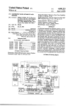
5 Claims, 16 Drawing Figures
KEYBOARD
uP
LABEL
FORMAT
H00
B00
F'LE
FORMAT DEFINITION
LABEL
ASSIGNMENT
RADIX
SELECTION
COIICATENATION
DEFINITION
ll
“iii?”
250
'B‘Ki’i
SW58
DATA
sass"
4I0 8 420
mamas,
é’iiiLFiIE
(CHARACTER 0R
GRAPHIC)
DISPLAY
CONTROLLER
MODULE
700
CRT
DISPLAY
I000
U.S. Patent
Jun. 19, 1984
Sheet 1 of 13
4,455,624
...... --FORMAT SPECIFICATION..-_--__-TRACE-CQWLETE-_..-_____---_-..__.._-_
CLOCK SLOPE [IIJ]
('l'g
F00
PROBE
LABEL ASSIGNMENT
P004
P003
P002
1 ---- --u
1 ---- --¢
1 ---- --a
AAAAAAM m
PODI
7 ---- --0
[122221;]
acnvs cHAiIiIéL's'
(A,a,c,u,E,F,x1
. . .
LOGIC‘
POLAlI-I’I‘EL
u -)-
E23
uunshcm. sass
. ..
$1
.
Eb
El @1 E
(am,oc'r,n:c,n|-:x)
.
:3
DESIGNATES
A
SELECTABLE
ENTRY FIELD
FIGURE |
______ _-TRACE spec IF 1 CAT |on-_..____..1'nAcE-couPL£TE---___..-.._..._--___-..___
LABEL
use
A
HEX
o
F
HEX am
occua
can
FIND m ssousuc: use
HE:
@ TIME
332'
03: ‘
sen nssnn'r ILL-21m
E
[Z]
T"cum! STATE] [Ell [Xi] B @111
CWNT Eli?! [1:55 IE IZI
FIGURE 2
_-...._______._TRACE LIST ____________ -_TRACE-COMPLETE _______________________ __
LABEL
use
A
HEX
n
F
HEX HEX
STATE coum'
use
SEQUENCE. . .QSCF. . . 5D. . .0. . .
SEQUENCE
SEQUENCE
START
+¢l
0352
QDEI
03E3
USES
03E4
@354
+09
O3El
DBEI
QBEI
.
4|- l?
4»! I
+I2
H3
E5
82
03
.
. .DSCE.
. . .
. . . . . . . I
C
D
l
. . .3354. . .47. . .D . .
+06
+67
+68
2
3
I
0
0
C
. . .03E3. . .E l . . .9 . . .
+02
+03
+64
4G5
A2
C6
82
A2
ID
5D
l
I
I
. . . . . . . . . . .|
6
0
0
. .50 . .
.0 . .
030E
DBEZ
D3E2
44
A2
C2
D
0
0
l
l
|
. . .
. . . .
. . .
. I
I
I
I
. .03E2. .
.66.
. .Q . .
+I4
+l5
QOEI
03E3
C6
82
0
G
. . . .
. .
.
. . . . I
I
I
+I6
USES
El
0
l
3
U.S. Patent
Jun. 19, 1984
Sheet 5 of 13
DISTRIBUTED MEMORY
OF DATA FILES
800
4,455,624
PHYSICAL LOCATION
RAM MEMORY 0N
DISPLAY DRIVER MOOuLE
900
DISPLAY DATA
F07
I000
\/0 AREA
AccEss T0
PRlNTER KEYBQARD
AND SELFTEST
HIO
I800
DATA ACQUISITION
MEMORY
(32 X 64 HI SPEED)
DISTRIBUTED 0N
MEASUREMENT CONTROL
MOOuLE
40o
IFFF
4000
ROM MEMORY lN
OF PROGRAM
MP AND l/O MOOuLE
800
47FF
6000
ROM MEMORY m
pP PROGRAM
‘(FFF
NOT usEO
FIGURE 8
OF AND \IO MOOuLE
800
U.S. Patent
Jun. 19,1984
Sheet 6 of 13
4,455,624
ROM
pP AND 1/0 \
MODULE
PRINTER
""
INTERFACE
‘ ‘ ’
INTERFACE
0
s00
"P
0-»
KEYBOARD
'0
RAM
(DATA DP
DATA DISPLAY)
DlSPLAY
DRIVER \
.->
coob?gh?m
cm
—>
DlSPLAY
MODULE
900
I000
\COMMUNICATIONS BUS e00
REcgg?uTgon
‘’
MODULE
PROBES I00
-4—-———
20D
ACQUISITION\
SYSTEM
250
l’
“"
\NDEX
MODULE
300
"EDDDDT
MODULE
400
FIGURE 9
_.-ACQUIS\TION
SYSTEM
BUS
50o
U.S. Patent
Jun. 19, 1984
Sheet 8 of 13
4,455,624
v
W
_a
A
£2.
w
m».
A
w2<
w
m»
A
w2<
.lIT
3*
A
£2
N__ERVE
aQHmo.hz6u4n<5tw.a
ET0i5l2
265x95:
>
Eloz‘m!s
mm:
US. Patent
Jun. 19, 1984
OUALIFIER
STATE
CONDITION
‘
Sheet 11 of 13
NTH OCCURRENCE
QUALIFIER STATE
NT“ OCCURRENCE
QUALIFIER STATE
2
4,455,624
OF THE FIRST
CONDITION
OF THE SECOND
CONDITION
3
I,
H
N-l
‘
:;
~
N
(
)
SELECTED DATA STATES ARE WRITTEN INTO
MEMORY CONTINUOUSLY IN RESPONSE TO THE
DETECTION OF THE NTH OCCURRENCE OF THE
NEXT TO THE LAST QUALIFYING STATE CONDITION.
THE STORAGE LOCATION OF THE SATISFACTION
OF THE TRACE SEQUENCE IS IDENTIFIED AND
THE DATA STORAGE TERMINATED IN RESPONSE
TO THIS EVENT AND THE SELECTED TRACE
POSITION (START, CENTER, ENDI
FIGURE I4
US. Patent
Jun. 19, 1984
Sheet 12 of 13
4,455,624
LABEL FORMAT FILE
LABEL LENGTH
(A)
BIT posmou
(A)
LOGIC POLARITY
(A)
CONVERSION
(A)
COLUMN POSITION
(A)
SOURCE OF DATA
(A)
DESTINATION
(A)
LABEL LENGTH
(B1
BIT POSITION
(B)
RESIDES m up
BATA FILE
k
A
> LABEL B
'
TABLE
J
.1
M:
> LABEL F
TABLE
J
FIGURE l5
U.S. Patent
Jun. 19, 1984
Sheet 13 of 13
4,455,624
LABEL
KEYJBSSRD
——>
+
:50
——-—>
FORMAT
FILE
' _’
(FORMAT LOGIC)
FORMAT DEFINITION
LABEL
ASSIGNMENT
RADIX
SELECTION
CONCATENATION
DEFINITION
Acoulsmon
“255105”
‘
—'_’
INPUT
DATA
usuomes
me a 420
ACQUISITION
pP
a0
l
DATA
STATES
DISPLAY
DATA FILE
(CHARACTER 0R
GRAPHIC}
DISPLAY
CONTROLLER
MODULE
700
FIGURE l6
cm
DISPLAY
I000
1
4,455,624
2
ternatively, the thirty-two bits could appear as “ten and
one half” digit octal or eigth-digit hexadecimal integers.
Note that whatever scheme is chosen affects the trace
LOGIC STATE ANALYZER WITH FORMAT
SPECIFICATION
speci?cation; quali?cation states for storage quali?ca
REFERENCE TO RELATED APPLICATIONS
S tion and the sequence states for a sequential trigger are
This application is a division of an earlier ?led co
pending application Ser. No. 210,462, filed on Nov. 25,
1980 by George A. Haag, et al., and amended to be
generally expressed in the same form used to display the
states in the trace.
It would be desirable if the user could partition the
input digital signals into groups and select an individual
entitled LOGIC STATE ANALYZER WITH STOR
AGE QUALIFICATION which is now U.S. Pat. No. 1° radix to be associated with each group. For example,
one group of the input digital signals may represent an
4,373,193. That application was contiuation of applica
address most conveniently represented in hexadecimal,
tion Ser. No. 075,787 entitled LOGIC STATE ANA
while another group may be data best depicted in octal.
LYZER ?led Sept. 17, 1979 by the same inventors, and
Still another group may be a collection of miscellaneous
which is now abandoned. That application was in turn
status and control lines best seen in binary. It would also
a division of a now abandoned application of the same
be convenient if these groups could be assigned sym
inventors and title, Ser. No. 828,138, ?led on Aug. 29,
bolic labels for ease in referring to the groups in the
1977.
trace and in the trace speci?cation. Such grouping,
The subject matter of the present application is re
individual radix selection and labelling is accomplished
lated to the subject disclosed in U.S. Pat. 4,040,025,
issued to Justin S. Morrill, Jr., on Aug. 2, 1977, and 20 by equipping a logic state analyzer with a mechanism to
which was ?led on Mar. 31, 1976.
receive a format speci?cation. The format speci?cation
The subject matter of the present application is also
is a user-determined rule of interpretation for the vari
related to the subject disclosed in U.S. Pat. No.
ous input digital signals. It speci?es which digital sig
4,100,532, issued to William A. Farnbach on July 11,
nals belong to the same group, what the associated radix
25 is, and what symbolic label refers to each individual
1978, and which was ?led on Nov. 19, 1976.
U.S. Pat. Nos. 4,040,025 and 4,100,532 to Merrill, et
group.
al. and Farnbach, respectively, are hereby expressly
DESCRIPTION OF THE FIGURES
incorporated by reference.
FIG. 1 illustrates the interactive format speci?cation
BACKGROUND AND SUMMARY
30
Logic state analyzers are used to monitor and record
sequences of states that occur in a collection of digital
signals in a system under test. A “state” is simply any
one of the 2'I logical patterns that n-many digital signals
display.
FIG. 2 illustrates the interactive trace speci?cation
display.
FIG. 3 illustrates a trace list display of the stored data
states.
may experience. A sequence of addresses or a sequence 35
FIG. 4 illustrates a trace graph display of the stored
of fetched instructions are examples of electrical activ
data
states.
ity describable as states in a microprocessing environ
FIG.
5 illustrates a trace compare output display list.
ment and that can be monitored by a logic state analyzer
FIG.
6
illustrates the input keyboard.
to record their “state flow”.
To monitor the ongoing sequence of states in a system 40 FIG. 7 illustrates a block diagram of the present in
vention.
under test a logic state analyzer samples the electrical
FIG. 8 illustrates the distributed memory addressing
values of the signals of interest at times determined by
of
the present invention.
one or more clock signals associated with the system
FIG. 9 illustrates the relationship between physical
under test. The sampled electrical values obtained are
compared to thresholds of selected value and polarity to 45 and logical addresses of the distributed memory of FIG.
8.
determine their logical values, each of which will be
FIG. 10 is a block diagram of the acquisition system.
either true or false, one or zero. Each resulting collec
FIG.
11 illustrates a multiple pattern recognition unit.
tion of ones and zeros for a sample is a state in the ongo
FIG. 12 illustrates a simpli?ed sequential triggering
ing sequence of states. It is also simply a binary value
that may be stored in a memory. A series of such stored SO circuit.
FIG. 13 illustrates the measurment and control mod
values is a record of the activity occurring in the system
ule.
under test. Such a record may be termed a trace.
FIG. 14 illustrates the data format of the data mem
To be useful, a logic state analyzer must produce a
ory.
trace that bears some desired relation to a speci?ed
FIG. 15 illustrates the format of the label format ?le.
event. The speci?cation of that relation can be simple or 55
complex, and may involve such notions as storage quali
?cation (i.e., not storing a state as a part of the trace
unless some qualifying criteria are met) and sequential
triggering. These various relations are set out in a trace
speci?cation.
The trace itself is often a tabular listing of captured
states. shown in the order in which they appeared. Un
less some additional mechanism is at hand, the states in
the tabular listing will appear as undifferentiated integer
numbers in some radix. For example, if the analyzer 65
FIG. 16 illustrates the logic flow of the display for
matting logic.
FORMAT SPECIFICATION
Data formatting permits the partitioning of 32 input
data channels into parameters of interest. Contiguous
data channels which behave as a single parameter may
be assigned to one of six labels (A-F). For example, in
FIG. 1, illustrating the interactive format speci?cation
each input as either a one or a zero, the trace would
display, 16 bits of an address bus have been assigned to
label “A", 8 bits of a data bus have been assigned to
label “D", 1 bit of data on pod 1 has been assigned to
consist of a table of thirty-two-bit binary integers. Al
label “F”, and 7 bits have been left unassigned (labeled
received thirty-two digital input signals and displayed
3
4,455,624
“X”). Further speci?cations and data manipulations are
made by referencing these labels. Each assigned label
may be independently declared to have a positive or
negative “logic polarity” and converted to an indepen
dently selected radix which can be binary, octal, deci
mal or hexedecimal. Further, the slope of the positive or
negative clock transition at which time the input data
channels are sampled can be selected (“clock slope”).
Keyboard entries to the microprocessor 800, as
shown in FIG. 16, permit the construction of the label
format ?le, shown in more detail in FIG. 15 which,
contains the format speci?cation parameters. This is
used to process the stored data states in the construction
of the alphabetically cancatenated ASCII display data
?le and the graphic display data ?le. Either of the dis
play data ?les is subsequently selected and used for
display purposes by the display control module 700 and
the CRT display 1000.
TRACE SPECIFICATION
The assigned input data channels are sampled at the
speci?ed clock transitions and are treated as one sam—
pled state. The trace speci?cation de?nes which of the
sampled states are to be stored for display and which
4
condition. FIG. 2 illustrates the selective trace of every
occurrence of a single state condition.
The count measurement performs a “time” of a
“state” count associated with each of the (64) states
stored and can be displayed in one of two formats:
absolute—the count from the trace position
relative—the count from the previous trace state
The time count is performed by counting the occur
rences of an internal clock between sequentially stored
states and the display is in the units of seconds. A state
count similarly counts the number of occurrences of a
speci?ed state condition ("count”) between sequentially
stored states. For example, specifying “any state”
would result in a count of the selected clock transitions
of the input data. In FIG. 2, a state count is performed
on the occurrences of a speci?ed state condition inter
mediate to each sampled state stored.
INTERNAL MEASUREMENT STORAGE
One complete measurement of 64 sampled states,
which includes the sampled states satisfying the state
conditions de?ning the state sequence and specifications
of the format, trace, and display, may be internally
stored. This “current measurement" may be stored or
sampled states are to be counted for count measure 25 exchanged with a “stored measurement” for later analy
ments. The trace speci?cation comprises a de?nition of
state conditions specifying the trace position, the selec
sis. A “trace compare” mode of operation (described
tive trace, and the count measurement. Each state con
stored trace with the current measurement and may be
utilized as a further quali?er on data storage.
dition de?nes a state of the assigned input data channels
in any combination of l’s, 0's, and/or X's (dont’t care).
In octal, decimal or hexedecimal bases the de?nition is
de?ned in terms of the appropriate alphamumerics and
X's.
A trace position may be selected to a start, center or
more fully below) compares results of a previously
DISPLAY SPECIFICATION
The output display format of the current measure
ment may be selected from a trace list, a trace graph, or
a trace compare.
A trace list, illustrated in FIG. 3, displays a listing of
end the selective trace in response to the input data 35
the stored states in their order of occurrence. Twenty
satisfying a prede?ned state sequence. In this descrip
tion it will be assumed that the trace position starts the
trace states, (one per line) are simultaneously presented
on the CRT display. The “ROLU' keys allow scanning
selective trace. A state sequence of up to seven state
of the 64 stored states. Each line comprises a line num
conditions must be satis?ed in a speci?ed order, ignor
ing intermedate state which do not satisfy the state 40 ber, the stored state alphabetically sorted into assigned
labels in their numerical base, and the time or state
sequence. The simplest state sequence is a single state
count is selected.
condition. Speci?c segments of branched, looped or
A trace graph, as shown in FIG. 4, presents a graph
nested forms of state ?ow may be directly located by
of the data magnitude of a speci?ed label versus the
properly de?ned state sequences. In addition, each state
condition in a state sequence may be required to occur 45 storage location for all 64 stored states. Each state is
given a vertical displacement corresponding to its bi
from 1 to 65536 times before the state condition is satis
nary magnitude and an increasing horizontal displace
?ed. This form of positioning will locate the nth pass of
ment for successive states in order of their occurrence.
a loop beginning at a given state condition. Clock delay
The result is a waveform analogous to oscilloscope
may be incorporated by de?ning the nth occurrence of
any state (an all don’t care state speci?cation). The trace
logic may also be speci?ed to restart the satisfaction of
the prede?ned state sequence if it is not satis?ed before
or concurrently with the location of a predetermined
restart state condition. A restart on “any state” requires
that the state sequence be satis?ed without any unspeci
?ed intermediate states. For example, FIG. 2 illustrates
the interactive trace speci?cation display for a trace
position starting upon the satisfaction of 4 state condi
tions in sequence. A restart state condition is also de
?ned.
The selective trace is a quali?cation to determine
which sampled states will be stored for display. One to
seven state conditions may be "OR” speci?ed for col
lection. Selectively tracing only sampled states of inter
displays of voltage magnitude. The label to be graphed
is selected by specifying the “graphed label”. Scaling of
state magnitude is controlled by specifying the "upper
limit" and “lower limit” on the vertical axis. Limits can
be speci?ed directly or dynamically varied with logrith
mic autoranging controls. These facilities allow any
portion of a graph to be magni?ed to a full scale presen
tation. The 20 points corresponding to the lines viewed
in the trace list are intensi?ed. The intensi?ed portion
also responds to the “ROLL" controls, and their corre
sponding absolute value may be read in the trace list.
A trace compare as illustrated in FIG. 5 presents a
tabular listing of the difference between results in the
“current measurement” and the data in the “stored
measurement”. The listing is formatted and rolled as in
est elminates the clutter of unnecessary states and mag 65 the trace list. The results of the two measurements are
exclusive OR’ed such that identical corresponding bits
ni?es the apparent size of the trace beyond its 64 terms.
Also, an occurrence term may be speci?ed so as to store
only every nth satisfaction of an “OR" speci?ed state
are displayed as zeros and unequal bits are displayed as
ones. In an octal base a “¢3” is equivalent to a binary
5
4,455,624
was 4m” and indicates that the right two bits are
different in the two measurements. Trace compare also
offers a "compared trace” mode which reruns a mea
surement until the current and stored measurement are
either equal or not equal. (STOP =, or STOP ¢) For
example, in FIG. 5 of the instrument has rerun trace
measurements until the “current measurement" equaled
the “stored measurement”, as indicated by the "STOP
=” speci?cation and revealed by the array of “0’”s in
the comparison.
6
signals are compared to the selected threshold voltages
and interpreted, and the data signals are latched in re
sponse to occurrences of the internal sampling clock.
The state recognition module 200 outputs the sampled
state to the high speed acquisition system bus 500. The
index module 300 accesses the sampled state on the
acquisition system bus 500, compares the sampled state
to the selected state conditions and determines the trace
position, selective storage events and state count events.
10 The measurement control module 400 also accesses the
TRACE MODES
Three trace mode options are provided. “Trace”
executes a single current measurement. "Continuous
trace” repeats the execution of a current measurement
continuously. “Compared trace” repeats the execution
of a current measurement until the desired comparison
with the stored measurement is obtained.
acquisition system bus 500 and stores state or time
counts and sampled data states in response to the events
detected by the index module 300.
The modules of the acquisition system 250 communi
cate with other system modules via the communications
bus 600, which provides a means for addressing selected
modules and for transferring selected data. The entire
system functions as a distributed memory, as illustrated
in FIG. 8. For instance, addresses between 1800 and
CLOCK ENABLE AND TRIGGER OUTPUTS
20 IFFF on the communications bus 600 access the state
A trigger output provides a triggering pulse for exter
nal instrumentation such as oscilloscopes. A 50 ns pulse
is generated each time the trace position is found. The
clock enable output is useful for gating clocks or inter
count measurements and the sampled data states stored
in the measurement control module 400 memories. FIG.
9 shows another representation of the system architec
ture, illustrating the relationship between the physical
rupting the device under test. A high signal level indi 25 couplings of FIG. 7 and the logical addresses of FIG. 8.
cates that the instrument is actively searching for the
Referring to FIG. 10, the index module 300 detects
trace position. It remains at the high signal level until
the
trace position by ?rst comparing the sampled state
the trace position has been found or the halt key is
on the acquisition system bus 500 with a quali?er state
depressed. Both outputs are suspended when the format
speci?cation is displayed to allow measurement of 30 condition stored in the multiple pattern recognition unit
315. The multiple pattern recognition unit 315 com
channel activity.
prises a digital pattern triggering circuit as described in
KEYBOARD AND SPECIFICATION
the copending patent application entitled "DIGITAL
DESIGNATION
PATTERN TRIGGERING CIRCUIT”, US. patent
application Ser. No. 743,188 ?led Nov. 19, 1976, by
Referring to FIG. 6, an illustration of the keyboard,
William A. Farnbach which is now US. Pat. No.
the keys are functionally segregrated into four blocks,
4,100,532.
As illustrated in FIG. 11, the multiple pattern
the "current measurement display", "entry", “edit”,
recognition unit 315 comprises 2 pairs of 8 sixteen by
and “execute". A power up sequence initially de?nes a
four bit memories providing for the detection of up to
defaul set of sepci?cations, displays the default format
speci?cation, then automatically selects a hexadecimal 40 eight quali?er state conditions, where each quali?er
state condition is identi?ed by a l, 0, X input, format (in
trace list display. Activation of the “ROLL DIS
PLAY” keys permits the presentation of any portion of
binary). Pattern selector 325 of FIG. 10 selects one of
the 64 states stored. To change the format speci?cation,
the “FORMAT SPECIFICATION" key is pressed.
tion unit and passes the selected output to the occur
the eight lines output from the multiple pattern recogni
The cursor keys in the edit block are used to move the
rence counter 345. The occurrence counter 345 counts
cursor, designating a selectable entry ?eld by a blinking
the occurrences of the selected quali?er state conditions
and provides an output in response of counting a speci
?ed number of occurrences of the selected quali?er
state condition. This output is termed a “break event"
and the sequencer logic 350 in response requests the
inverse video ?eld on the interactive display.
"
The trace speci?cation can be edited by selecting the
trace speci?cation interactive display by activating the
“trace speci?cation” key. Editing is accomplished in the
same manner as the format speci?cation is edited. A
general description of the functions of the individual
keys is given in Appendix A. A detailed description of
the interactive display entry ?elds is given in Appendix
B.
DETAILED DESCRIPTION
Input states are sensed through 32 high impedance
pattern selector 325 to select the next sequential quali
?er state condition and requests the occurrence counter
345 to select the corresponding count. The sequencer
logic 350 also outputs a “N- 1" event ?ag in response
55 to detection of the occurrence of the “NEXT TO
LAST BREAK EVENT". A simpli?ed sequential trig
gering circuit is illustrated in FIG. 12 where the multi
ple pattern recognition unit 315 incorporates the func
tions of the multiple pattern recognition unit 315 and of
variable threshold data probes at rates up to l0 MHz.
The data probes 100, illustrated in FIG. 7, are seg 60 the pattern selector 325. The sequence logic 351 incor
porates the functions of the sequence logic 350 except
mented into four 8 bit data pods and a ?fth pod for
that the ?nal trigger is output in response to the comple
clock sensing. Each pod may be preset to 'I'I‘L logic
tion of the state sequence. Another method of imple
threshold or variably adjusted in the range of + 10 to
menting the multiple pattern recognition unit 316 would
— 10 volts to interpret input logic levels.
The 32 input data channels and the clock signal from 65 be to have 3 selector bits be the most signi?cant bits in
the address, allowing the comparator to sequence
the data probes 100 are input to the state recognition
through various segments of memory when comparing
module 200. An internal sampling clock is generated in
sequential state conditions of the state sequence.
response to the selected clock slope, the input data
4,455,624
7
Referring again to FIG. 10, the selective trace is
incorporated in a similar manner except that the trace
selector 320 of FIG. 10 can "OR” any combination of
the AME lines. A trace occurrence counter 340 outputs
a trace event flag upon counting each "nth” “ORED"
AME event.
The restart unit 310 causes the sequence logic 350 to
restart the satisfaction of the state sequence subsequent
to the detection of a selected restart state condition. The
8
into the remaining memory locations, writing over the
oldest data when the memory is ?lled. The trace posi
tion address of the memory location containing the state
condition resulting in the ?nal trigger is stored in a
5 register and sampled states are written into the appro
priate number of remaining storage locations. For ex
ample, if the trace was de?ned to end on the detection
of the trace portion, no sampled states would be written
subsequent to the detection of the trace position. The
restart unit is disabled for the data state corresponding 10 order of occurrence of the stored data is easily recon
structed by recovery of the trace position address ap
to the detection of a break event by sequencer logic 350
pearing on the communications bus 600 as illustrated in
which permits the state sequence to be satis?ed without
FIG. 8. Count selector and synchronizer 450 controls
any unspeci?ed intermediate state by setting the restart
the measurement counter 430, whose contents are
state condition to “any state”.
The state count unit 305 strobes a counter in the 15 stored in count memory 420 upon update of the mem
ory address. The low speed control 480 provides a low
measurement control module 400 each time the selected
speed interface for programming the high speed control
state condition to be counted is detected.
460 and for selecting and latching data for the commu
The measurement and control module 400 is illus
nications bus 600 interface.
trated in FIGS. 10 and 13. The event ?ags from index
module 300 are input to the high speed control 460 and 20 The strobe generator 400, illustrated in FIGS. 10 and
13, generates a sequence of strobes which, when cou
determine which sampled states on the acquisition sys
pled with a series of data latches (not shown) and timing
tem bus 500 are to be stored. The high speed control 460
logic (not shown) effectuate the orderly performance of
addresses the data memory 410 and the count memory
machine tasks. In effect, a number of sampled states are
420 accordingly. FIG. 14 illustrates the data format of
the data memory 410. The sampled state conditions 25 simultaneously in various stages of processing at any
one time and are “pipelined” through the required logic
resulting in break events are sequentially stored in loca
blocks.
tions 1 (N —l). Upon detection of the “N-l" event
?ag, sampled state conditions are sequentially written
APPENDIX A
GENERAL DESCRIPTION -- KEYBOARD
CURRENT MEASUREMENT DISPLAY
LINES 3 THROUGH 24 ARE DEPENDENT ON THE DISPLAYED MENU CHOSEN,
WHICH MAY BE SELECTED BY KEYS IN CURRENT MEASUREMENT BDOCK:
SELECT CDOCK SLOPE AND FORMAT 32 CHANNELS
FORMAT SPECIFICATION
INTO LOGICAL LABELS, DESIRED LOGIC
POLARITY AND NUMERICAL BASE.
DEFINE TRACE POSITION. SELECTIVE TRACE
TRACE SPECIFICATION
AND COUNT MEASUREMENT.
DISPLAY RESULTANT CURRENT TRACE AND
LIST
COUNT DATA.
GRAPH RESULTANT CURRENT TRACE DATA FOR
GRAPH
SELECTED LABEL. THE 20 INTENSIFIED DOTS
CORRESPOND TO TRACE LIST DATA.
DISPLAY THE “EXCLUSIVE OR” OF VALID CURRENT
COMPARE
DATA WITH VALID STORED DATA, AND SELECT
VS
COMPARED TRACE MODE.
STORE
VIEW TRACE LIST OR TRACE COMPARE DATA.
ROLL DISPLAY
TRACE GRAPH SHOWS INTENSIFIED DOTS THAT
REPRESENT THE TRACE LIST DATA DISPLAYED.
GRAPH -+
<—GRAPH
ENTRY
ALL PROGRAM ENTRIES ARE MADE IN INVERSE VIDEO FIELDS AT THE
BLINKING CURSOR, AND MAY BE CHANGED BY THE ENTRY BLOCK OF KEYS:
FIELD SELECT [ ]
0-9, A-F, X
ALL FIELDS ENCLOSED WITH BRACKETS [ ]
ARE CHANGED BY THIS KEY. THE l6l0A
SELECTS ONLY ALLOWED CHOICES.
ALL OTHER FIELDS MAY BE CHANGED USING
THESE KEYS.
EDIT
DISPLAYED MENUS MAY BE EDITED BY THE EDIT BLOCK OF KEYS:
USED IN THE TRACE SPECIFICATION MENU ONLY
DELETE
INSERT
TO OPTIONALLY DELETE OR INSERT STATES
TO SPECIFY TRACE POSITION AND SELECTIVE
TRACE. A MAXIMUM OF 8 STATES MAY BE USED
BETWEEN TRACE POSITION AND SELECTIVE
TRACE.
RETURNS THE DISPLAYED MENU TO A KNOWN (PRESET,
DEFAULT
TRACEABLE) CONDITION.
INCR
DECR
USED IN TRACE GRAPH ONLY TO AUTOMATICALLY
CHANGE UPPER OR LOWER GRAPH LIMITS.
IélSED TO MOVE THE BLINKING CURSOR TO A DESIRED
IELD.
EXECUTE
THE REMAINING KEYS ARE THE EXECUTE BLOCK OF KEYS:
1, KEY SAVES CURRENT SPECIFICATION AND
CURRENT MEASUREMENT
DATA MEASUREMENT IN A STORED FILE. THE
4,455,624
9
10
APPENDIX A-continued
GENERAL DESCRIPTION -- KEYBOARD
STORED MEASUREMENT
CURRENT SPECIFICATION AND DATA REMAIN
UNCIIANGED.
1 1 REY EXCHANGES THE CURRENT AND STORED
MEASUREMENT FILES.
PRINTS THE CURRENT DISPLAY, EXCEPT TRACE GRAPH.
ON AN HP 9866 LINE PRINTER. TRACE LIST AND TRACE
COMPARE WILL PRINT THE CURRENT PAGE AND ANY
REMAINING DATA IN MEMORY.
ExECUTES THE CURRENT SPECIFICATION, AND IF
DISPLAY IS THE FORMAT OR
TRACE SPECIFICATION, TIIE 1610A SWITCHES THE
DISPLAY To TRACE LIST.
IF TRACE Is HELD DOWN. THE MEASUREMENT Is
TRACED CONTINUOUSLY.
IF THE COMPARE TRACE MODE Is SET FOR [STOP=]
OR [STOP#] THE MEASUREMENT Is TRACED
UNTIL THE CONDITION Is MET. THE
PRINT
TRACE
INSTRUMENT STATUS (1ST LINE) IS EITHER
“COMPARED TRACEFAILED", (IMPLIES CONDITION
NOT MET) OR “COMPARED TRACE-COMPLETE"
(IMPLIES CONDITION MET).
STOP
STOPS ANY MEASUREMENT TRACE, COMPARED TRACE
OR PRINT IN PROCESS.
APPENDIX B
DETAILED FIELD(S) DESCRIPTION
CLOCK SLOPE:
EXAMPLES:
CLOCK SLOPE [+1
CLOCK SLOPE [-1
PURPOSE:
TO SELECT THE CLOCK TRANSITION USED TO STROBE POD DATA INTO THE
1610A.
LABEL ASSIGNMENT AND ACTIVE CHANNELS:
EXAMPLE:
POD4
POD3
PODZ
PODI
7----0
7-----0
7----0
7-----0
AAAAAAAA AAAAAAAA DDDDDDDD XXXXXXXF
III!!!"
IIIII!!!
III!!!"
I
ACTIVE CHANNELS
PURPOSE:
TO ASSIGN LABELS A,B,C,D,E OR F TO ANY NUMBER OF
CONTINUOUS CHANNELS INDEPENDENT OF POD BOUNDARIES.
IN THE ABOVE EXAMPLE THE LABEL A IS ASSIGNED
TO 16 BITS OF PODS AND POD4, AND MAY REPRESENT
A I6 BIT ADDRESS. LABEL D IS ASSIGNED 8 BITS
ON PODZ AND MAY REPRESENT AN 8 BIT DATA BUS. LABEL
F IS A SINGLE BIT OUALIFIER (READ/WRITE) AND IS
ASSIGNED TO THE LEAST SIGNIFICANT BIT ON PODI.
ANY UNUSED CHANNELS MAY BE TURNED OFF BY PUTTING AN “X"
IN THOSE CHANNELS.
COMMENT: AS MANY AS SIX LABELS OR AS FEW AS ONE MAY BE ASSIGNED
ACROSS THE 32 CHANNELS, IF A LABEL IS SPLIT, SUCH AS
AABBBAAA
(LABEL IS NOT CONTINUOUS)
THEN AN ERROR MESSAGE “ERROR-SPLIT LABEL"IS DISPLAYED
AND THE CURSOR IS LOCKED TO THE LABEL ASSIGNMENT FIELDS
UNTIL THE ERROR IS CORRECTED.
PRESSING THE DEFAULT KEY WILL ASSIGN LABEL F TO ALL 32
CHANNELS.
ACTIVE CHANNELS ARE SHOWN BY ‘1" MARKS FOR EACH ASSIGNED
CHANNEL. ABSENCE OF "I" INDICATES LOW CHANNEL (BIT)
ACTIVITYI AND IS A GOOD INDICATOR THAT A POD CLIP MAY
HAVE FALLEN OFF. CHANNEL ACTIVITY IS NOT DISPLAYED
WHILE 16IOA IS TRACING.
IF A POD IS CONNECTED TO THE DATA PORT ON REAR OF IGIOA,
THE CHANNEL ACTIVITY "1" FOR LEAST SIGNIFICANT 2 BITS
IS NOT SHOWN (DUE TO SYNCHRONOUS 8 BIT COUNT AND
1610A).
LOGIC POLARI'I‘Y:
EXAMPLE:
LABEL
LOGIC POLARITY
(+* _)
A
D
F
[—1
[-1
[+1
PURPOSE:
TO SELECT A LOGIC POLARITY FOR EACH ASSIGNED LABEL.
NUMERICAL BASE:
EXAMPLE:
LABEL
A
B
F
NUMERICAL BASE
(BIN, OCT. DEC, HEX)
PURPOSE:
[HEX] [OCT]
[BIN]
To SELECT A NUMERICAL BASE OF HEXIDECIMAL (HEX),
OCTAL (OCT), DECIMAL (DEC), OR BINARY (BIN) FOR
EACH ASSIGNED LABEL.
TRACE POSITION:
4,455,624
11
12
APPENDIX B-continued
DETAILED FIELD(S) DESCRIPTION
EXAMPLE:
[START] TRACE
[CENTER] TRACE
[END] TRACE
PURPOSE:
TO SELECT WHETHER THE TRACE STARTS, IS CENTERED
OR ENDS UPON A DESIGNATED STATE (wHICH MAY BE
CALLED THE TRIGGER STATE). ADDITIONALLY, THE
TRIGGER STATE MAY BE DEFINED To BE A SPECIFIED
NUMBER OF OCCURRENCES OF A DESIGNATED STATE.
LABEL
A
OCCUR
BASE
HEX
DEC
FIND IN SEQUENCE
I0
0000!
THEN
20
0000]
THEN
30
00005
[START] TRACE
40
0000]
EXAMPLE:
SEQ. RESTART [ON]
50
COMMENT: THIS EXAMPLE HAS THE FOLLOWING MEANING FOR DEFINING
TRACE POSITION:
FIND IN SEQUENCE 00001 OCCURANCE OF STATE 10, THEN
THE 00001 OCCURANCE OF STATE 20, THEN THE 0000s 0CCURANCE
OF STATE 30. AND [START] TRACE AT 00001 OCCURANCE
OF STATE 40.
IF DURING THIS SEQUENCE THE RESTART STATE 50 IS
ENCOUNTERED BEFORE REACHING THE 00001 OCCURANCE OF
STATE 40, THE MEASUREMENT RESTARTS TO AGAIN FIND IN SEQUENCE
THE 00001 OCCURANCE OF STATE 10, THEN 00001 OCCURANCE
OF STATE 20. ETC.
NOTE:
IF A SEQUENCE STATE IS DEFINED TO BE THE SAME AS THE RESTART STATE, THE SEQUENCE STATE DOMI
NA'I'ES. IF [CENTER] OR [END] WERE SELECTED, SELECTIVE TRACE STARTS AT COMPLETION OF 5 OCCURANCES
OF STATE 30 (SEE SELECTIVE TRACE)w
SELECTIVE TRACE:
EXAMPLE:
LABEL
A
OCCUR
[ALL STATES]
PURPOSE:
EXAMPLE:
TO TRACE ALL STATES.
LABEL
BASE
TRACE
[ONLY STATE]
PURPOSE:
COMMENTS:
A
HEx
OCCUR
DEC
60
00001
OR
1x
OR
sx
TO SELECT IVELY TRACE DESIRED STATES; STATES NOT MEETING THE
SELECTION CRITERIA ARE SIMPLY NOT INCLUDED IN THE TRACE.
THE ABOVE EXAMPLE HAS FOLLOWING MEANING:
DO A SIMULTANEOUS TRACE OF 00001 OCCURANCE
OF STATES 60 OR 7X (70 TO 7F) OR
sx(a0 TO 8F).
COUNT:
EXAMPLE:
LABEL
BASE
A
HEx
COUNT [OFF]
COUNT [STATE]
7x
COUNT [TIME]
PURPOSE:
TO SELECT COUNT MEASUREMENT TO BE [OFF], OR IF ON, TO BE
COMMENT:
wHEN COUNT IS [OFF], THE TRACE LIST DOES NOT SHOW
COUNT DATA FOR THE NEXT TRACE MEASUREMENT.
WHEN COUNT [STATE] IS SELECTED A 32 BIT COUNT OF THE
SELECTED STATE 7x (10 TO 7F) 15 STORED IN MEMORY
wITH EACH POD DATA STATE STORED. THE RESULTANT COUNT
DATA IS DISPLAYED IN THE TRACE LIST FOR THE NExT TRACE
MEASUREMENT.
WHEN COUNT [TIME] IS SELECTED A COUNT vALUE OF TIME IS
STORED FOR EACH POD DATA STATE STORED IN MEMORY. THE
RESULTANT TIME DATA IS DISPLAYED IN THE TRACE LIST FOR
THE NExT TRACE MEASUREMENT
COUNT [STATE] OR COUNT [TIME].
STATE COUNT OR TIME [ABS], [REL]:
EXAMPLE:
LABEL
BASE
A
HEX
STATE COUNT
DEC
SEQUENCE
SEQUENCE
SEQUENCE
l0
20
30
—
O
—
I043
1033
1023
START
+ BI
+02
+03
40
60
70
71
+
+
+
0
20
30
31
LABEL
BASE
A
HEX
[ABS]
STATE COUNT
DEC