1
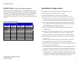
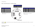
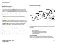
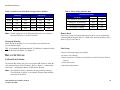
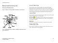
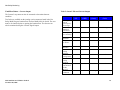
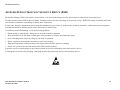
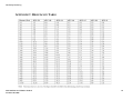
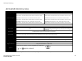
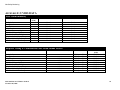
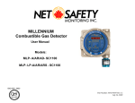
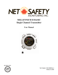
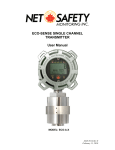
Ultraviolet / Infrared
Flame Detector
User Manual
Model:
UV/IRS-A-X OR AR-X
MAN-0075 Rev 03 UVIRS-A-X/AR-X
November 06, 2008
Net Safety Monitoring
IMPORTANT INFORMATION
This manual is for informational purposes only. Although every effort has
been made to ensure the correctness of the information, technical
inaccuracies may occur and periodic changes may be made without notice.
Net Safety Monitoring Inc., assumes no responsibility for any errors
contained within this manual.
If the products or procedures are used for purposes other than as described in
the manual, without receiving prior confirmation of validity or suitability,
Net Safety Monitoring Inc., does not guarantee the results and assumes no
obligation or liability.
Complete instructions have been provided for the safe service, use,
installation, configuration and maintenance of this product in compliance
with EN 60079-14 and EN 60079-10 for hazardous locations. Ensure this
manual is read thoroughly before installation or operation.
No part of this manual may be copied, disseminated or distributed without
the express written consent of Net Safety Monitoring Inc.
Net Safety Monitoring Inc., products are carefully designed and
manufactured from high quality components and can be expected to provide
many years of trouble free service. Each product is thoroughly tested,
inspected and calibrated prior to shipment. Failures can occur which are
beyond the control of the manufacturer. Failures can be minimized by
adhering to the operating and maintenance instructions herein. Where the
absolute greatest of reliability is required, redundancy should be designed
into the system.
Warranty
Net Safety Monitoring Inc., warrants its sensors against defective parts and
workmanship for a period of 24 months from date of purchase; other
electronic assemblies for 36 months from date of purchase.
No other warranties or liability, expressed or implied, will be honoured by
Net Safety Monitoring Inc.
Contact Net Safety Monitoring Inc or an authorized representative for details.
We welcome your input at Net Safety Monitoring. If you have any comments
please contact us at the phone/address below or visit our web site and
complete our on-line customer survey: www.net-safety.com.
Contact Information
Net Safety Monitoring Inc.
2721 Hopewell Place NE
Calgary, AB
Canada
T1Y 7J7
Telephone: (403) 219-0688 Fax: (403) 219-0694
www.net-safety.com
E-mail: | Email: [email protected]
Copyright © 2007 Net Safety Monitoring Inc.
Printed in Canada
MAN-0075 Rev 03 UVIRS-A-X/AR-X
November 06, 2008
3
TABLE OF CONTENTS
Important Information ...................................................................................... 3 Warranty .......................................................................................................... 3 Contact Information ......................................................................................... 3 Introduction...................................................................................................... 5 Spectral Sensitivity Range........................................................................... 5 Locate Detector ........................................................................................... 5 Typical applications ..................................................................................... 5 Potential ignition sources............................................................................. 5 Potential inhibitors ....................................................................................... 6 Absorbing Gases ......................................................................................... 6 Immune ........................................................................................................ 6 Range .............................................................................................................. 6 Field of View (as per FM and NFPA definition) ............................................... 7 Installation Considerations .............................................................................. 7 Unpack ............................................................................................................ 8 Reflector Positioning ....................................................................................... 9 Field Installation ............................................................................................ 10 Wiring......................................................................................................... 10 Grounding .................................................................................................. 10 Sealing ....................................................................................................... 10 Connecting................................................................................................. 11 Detector Setup .............................................................................................. 13 System Sensitivity ..................................................................................... 13 DIP Switch Access ................................................................................. 13 Sensitivity Setting ................................................................................... 13 Time Delay Setting................................................................................. 13 Closing the Housing ............................................................................... 14 Relay Settings ............................................................................................... 14 Coil and Latch Status ................................................................................ 14 Remote Reset ........................................................................................ 14 Final Setup ............................................................................................. 14 Detector Functionality ................................................................................... 15 Detector Window/Lens .............................................................................. 15 Start Up Procedure .................................................................................... 15 System Check ........................................................................................... 15 Monitor ....................................................................................................... 15 Condition Status—LEDs ........................................................................ 15 Condition Status—Current Output ......................................................... 16 Detector Maintenance ................................................................................... 17 Testing ....................................................................................................... 17 Manual Check Procedure .......................................................................... 17 Automatic Visual Integrity (VI) Test ........................................................... 17 Manual VI Test........................................................................................... 17 Test Procedure....................................................................................... 18 Cleaning Window/Lens and Reflector ........................................................... 19 O-ring ......................................................................................................... 19 How To Return Equipment ............................................................................ 20 Troubleshoot ................................................................................................. 21 Appendix A: Common UV Absorbing Gases ................................................ 22 Appendix B: Electrostatic Sensitive Device (ESD)........................................ 23 Appendix C: Resistance Table ...................................................................... 24 Appendix D: Specifications ........................................................................... 25 Appendix E: UVIRS DATA ............................................................................ 26 Appendix E: UVIRS DATA (continued) ........................................................ 27 Net Safety Monitoring
INTRODUCTION
Locate Detector
The UV/IRS is a smart, stand-alone fire detector, combining sensors for both
the ultra-violet and infrared spectra. The detector is designed to respond to a
wide range of hydrocarbon based fires and the rugged design is ideal for both
indoor and outdoor applications.
When positioning fire detectors, consider such factors as, distance from the
fire, type of fuel and temperature, as well as any environmental factors which
may influence the detector’s response to radiation.
The microcontroller monitors and analyzes each sensor to identify a variety
of flame conditions. Only when the defined detection criteria for both IR and
UV sensors indicate a fire condition will the detector alarm.
Spectral Sensitivity Range
The UV/IRS fire detector responds to UV radiation wavelengths of 185 to
260 nanometres (1850 to 2600 angstroms) and IR radiation in the 4.4 micron
range. Note that UV radiation reaching the earth from the sun does not
extend into the sensitivity range of the detector, nor does radiation from
normal artificial lighting, such as fluorescent, mercury vapour and
incandescent lamps.
Typical applications
• automotive-manufacturing and paint spray booths
• aircraft hangars (commercial and military)
• offshore platforms, refineries, pipelines and production ships
• printing industry facilities
• oil, gas and petrochemical refineries/production/storage/off loading/shipping
• various production, processing and storage facilities
• munitions handling
• warehouses (flammable liquids/toxic gases) and tank farms (floating/non-floating)
• power generation pumps, generators and unmanned stations
Potential ignition sources
A hydrocarbon fuel-based fire can erupt in areas where the following are
found:
• alcohol
• gasoline
• paint
• aviation fuel
MAN-0075 Rev 03 UVIRS-A-X/AR-X
November 06, 2008
• acetylene
• natural gas
• solvents
• heptane/naptha
• diesel and hydraulic fuel
• liquefied natural gas (LNG)
• liquefied petroleum gas (LPG)
• propane/methane/butane
5
Net Safety Monitoring
Potential inhibitors
RANGE
A potential inhibitor is anything located between the detector and a potential
fire source which could prevent the UV/IRS from detecting a fire or reduce
its sensitivity to fire. Possible inhibitors include but are not limited to the
following:
• Solid objects such as machinery, glass or plexiglass between the detector
and potential fire source
• Water, fog, rain, dirt or dust on the detector window or heavy smoke
between the detector and potential fire source
Absorbing Gases
A further potential inhibitor may be the presence of UV absorbing gases or
chemical vapours between the detector and source of potential fire. Such
gases could impede the detector’s ability to detect a UV flame source. Small
concentrations of these gases may not be sufficient to obstruct the sensor but
high concentrations may impede the UV sensor. Moving the detectors closer
to the probable fire source and increasing the sensitivity can, in some
circumstances, overcome this issue (refer to Appendix A ).
Immune
The practical application distance is directly related to the intensity of the
ultraviolet/infrared radiation source.
Table 1: Response Testing
Response Testing
Fuel
n-Heptane
Methanol
Methane
Propane
Jet Fuel
Diesel
Lube Oil
Ethanol
Gasoline
Size
1' x 1'
1' x 1'
36" Plume
16" Plume
1' x 1'
1' x 1'
1' x 1'
1' x 1'
1' x 1'
Distance
(ft/m)
140/42.7
40/12.2
100/30.5
35/10.6
90/27.4
80/24.4
50/15.2
60/18.3
120/36.6
Average
Response Time
(Seconds)
10.6
9.7
5.9
4.0
4.7
5.1
6.7
5.7
5.9
NOTE: The response time is based on zero time delay and maximum
sensitivity.
The UV/IRS exhibits excellent immunity to many conditions/activities
including but not limited to the following:
• steady hot body radiation
• sunlight (direct/reflected)
• artificial lighting
• arc welding radiation
MAN-0075 Rev 03 UVIRS-A-X/AR-X
November 06, 2008
6
Net Safety Monitoring
Field of View (as per FM and NFPA definition)
The area in front of a flame detector, where a standardized flame can be
detected and which is specified by distance and angle off the central axis, is
the Field of View. The referenced flame is moved to 50% of the maximum
on-axis detection distance and then moved off-axis horizontally and
vertically to the limit of detection. These off-axis angle limits specify Field
of View.
Table 2: Field of View Testing
Field of View Testing
Fuel
n-Heptane
Methanol
Methane
Propane
Jet Fuel
Diesel
Lube Oil
Ethanol
Gasoline
Size
1' x 1'
1' x 1'
36" Plume
16" Plume
1' x 1'
1' x 1'
1' x 1'
1' x 1'
1' x 1'
Horizontal
Degrees
120 (+60, -60)
120 (+60, -60)
120 (+60, -60)
110 (+55, -55)
120 (+60, -60)
120 (+60, -60)
120 (+60, -60)
120 (+60, -60)
120 (+60, -60)
Vertical
Degrees
120 (+60, -60)
105 (+45, -60)
95 (+35, -60)
95 (+35, -60)
95 (+35, -60)
95 (+35, -60)
95 (+35, -60)
100 (+40, -60)
95 (+35, -60)
NOTE: Data based on Maximum Sensitivity Setting.
Installation Considerations
The following should be considered when mounting flame detectors.
• Point detector toward where the flame is expected.
• Ensure an unobstructed view of the area to be monitored.
• Employ more than one detector to ensure the hazard is fully covered.
• Mount the detector a few feet (about 1 metre) below the ceiling so it can
respond before being blocked by smoke accumulation at the ceiling.
• If dense smoke is likely to accumulate prior to flame (as in an electrical
fire), supplement UV/IR detector(s) with other protection such as Net
Safety Monitoring Airborne Particle Monitor.
• The detector should be accessible for cleaning the window/lens and
reflector surfaces.
• Tilt detector downward a minimum of 10 to 20° to reduce dirt and dust
accumulation which could obscure the detector’s viewing window.
• Securely mount detector so as to reduce vibration as much as possible.
• When located outside, detector sensitivity can be reduced by heavy fog,
rain and/or ice.
• Consider shortening the time delay settings when smoke is expected to
accumulate before or during a fire (refer to "System Sensitivity").
• Reduce sensitivity setting if false alarms, related to surrounding activities,
occur (refer to "System Sensitivity" )
• When installed near or on water (such as an off shore platform), be sure to
take into account the low horizon level when tilting detector downward.
• UV radiation, other than that produced by an actual fire, is referred to as
"background UV". An example of a high level of background UV could
be a flare stack situated outside of a building. The UV radiation produced
by this flare, in conjunction with a false alarm IR source, may be
MAN-0075 Rev 03 UVIRS-A-X/AR-X
November 06, 2008
7
Net Safety Monitoring
detected as fire when a door to the building is opened. Windows or other
reflective surfaces may also cause unusually high levels of UV radiation
to enter the building from the flare. In a situation like this, the fire
detection system response must be carefully checked and the sensitivity
level adjusted high enough so that this "background UV" will not cause
false alarms.
Figure 1: Detector Housing and Swivel Mount
• UV fire detectors respond to radiation other than ultraviolet. X-rays in
conjunction with a false alarm IR source can activate the detector. Since
X- rays are often used in industrial inspection it may be necessary to
disable the system when inspections are conducted nearby.
• For protection against line surge and extraneous transients, it is required to
install detector wires in a braided flexible conduit less than 5 feet.
UNPACK
Carefully remove all components from the packaging. Check components
against the enclosed packing list and inspect all components for obvious
damage such as broken or loose parts.
If you find any components missing or damaged, notify the representative or
Net Safety Monitoring immediately.
Note: Units are factory sealed.
MAN-0075 Rev 03 UVIRS-A-X/AR-X
November 06, 2008
8
Net Safety Monitoring
Figure 2: Dimensional Drawing
REFLECTOR POSITIONING
Ensure the external VI reflector is placed directly over the VI Emitters (refer
to Figure 7 for VI source location). Also ensure the detector is mounted with
the VI reflector in the top position, centred over the yellow dot.
Figure 3: Position of VI Reflector
MAN-0075 Rev 03 UVIRS-A-X/AR-X
November 06, 2008
9
Net Safety Monitoring
FIELD INSTALLATION
WARNING:
• Wiring codes and regulations may vary. Compliance with regulations
is the responsibility of the installer. Wiring must comply with
applicable regulations relating to the installation of electrical
equipment in a hazardous area. If in doubt, consult a qualified
official before wiring the system.
• This equipment is only suitable for ATEX Category 2 (Zone 1)
locations.
• Equipment must be installed in compliance with EN 60079-14.
• The permanently connected cable need appropiate protection of the
free end of the cable. Use an ATEX certified Junction Box.
• Do not open housing and expose electronics in a classified area .
(Do not open when an explosive atmosphere may be present)
• Ensure area is de-classified prior to opening housing.
• The parts of the bushing outside the flameproof enclosure have to be
protected from mechanical impact by means of Ex
components(e.g.Enclosure, Thread adapters, Conduit)
Wiring
For protection against line and extraneous transients, it is required to install
detector pig tail lead wires in a braided flexible conduit less than 5 feet in
length to the termination box. From the termination box to the power supply
the recommended detector cable is four conductor (or greater), shielded 18
AWG rated 300 V for distances up to 150 feet. When cable is installed in
conduit, the conduit must not be used to support wiring to any other
electrical equipment. Detectors can be located over 150 feet and up to 2000
feet, if 16 AWG shielded conductor is used. The maximum distance between
the detector and the power supply is limited by the resistance of the
connecting wiring, which is a function of the gauge of the wire being used.
MAN-0075 Rev 03 UVIRS-A-X/AR-X
November 06, 2008
Refer to “Appendix C, Resistance Table (Ohms)". The unterminated wires
must be terminated in a suitable certified ATEX enclosure or fitting.
Grounding
An external ground is required. The flame detector must also be connected to
an ATEX certified junction Box to ensure adherence to safety conditions. If
the junction box is non-metallic, the external ground must be provided by
some other means.
SEALING
Water-proof and explosion-proof conduit seals are recommended to prevent
the accumulation of moisture within the junction box. Seals should be
located as close to the device as possible and not more than 18 inches
(46 cm) away. Explosion-proof installations may require an additional seal
where conduit enters a non-hazardous area. When pouring a seal, use a fibre
dam to ensure proper formation of the seal. Seals should never be poured at
temperatures below freezing.
The jacket and shielding of the cable should be stripped back to permit the
seal to form around the individual wires. This will prevent air, gas and water
leakage through the inside of the shield and into the enclosure.
It is recommended that explosion-proof drains and conduit breathers be used.
Changes in temperature and barometric pressure can cause 'breathing' which
allows moist air to enter conduit. Joints are seldom enough to prevent
'breathing'.
10
Net Safety Monitoring
CONNECTING
There are two configurations of the UV/IRS available: Analog (A) and
Analog with Relays (AR). Review the following figures for wiring and other
settings specific to A or AR configurations.
WARNING:
Prior to wiring, ensure power is disconnected. Improper
wiring can cause damage to the detector.
Figure 4: Wire Colour Coding — ANALOG
FLAME DETECTOR WIRE CODING
Wire
Function
Colour
Green
Earth Ground (GND)
Blue
Manual VI (MVI)
White
Vdc (+)
Black
Com (-)
Red
4-20mA Signal Output
WARNING:
For Analog models, if terminations are being done in a
Net Safety Multi-Purpose Junction Box, refer to MAN-0081 for specific
terminal designations.
MAN-0075 Rev 03 UVIRS-A-X/AR-X
November 06, 2008
11
Net Safety Monitoring
Figure 5: Junction Box Connection — ANALOG/RELAY BOARD
NO
NC
COM
FIELD WIRING
Function
Remote Reset
Manual VI
4-20mA Signal Output
Com (-)
Vdc (+)
Note: Terminate shield of field wiring at one end
only to Earth Ground.
FIRE RELAY
FAULT RELAY
NO
NC
COM
NO
NC
COM
Terminal
RRst
MVI
SIG
-PWR
+PWR
Relay Contacts
Normally Open
Normally Closed
Common
RRst
MVI
SIG
-PWR
+PWR
B
R
BLK
W
Terminal
B
R
BLK
W
FLAME DETECTOR WIRING
Wire
Function
Blue
Manual VI / Communication
Red
4-20mA Signal Output
Black
Com (-)
White
Vdc (+)
Green
Earth Ground (GND)
Note: Connect Green Wire ( Earth GND) to
ground lug of housing.
OFF
ON
1
2
Dip Switch (See “Relay
Settings” for details).
WARNING:
If the 4-20mA signal is not used, connect a jumper between the terminals for 4-20mA signal output (SIG) and –PWR (Com-) on the Field
Wiring terminal block.
MAN-0075 Rev 03 UVIRS-A-X/AR-X
November 06, 2008
12
Net Safety Monitoring
DETECTOR SETUP
Figure 6: DIP Switch Location
SYSTEM SENSITIVITY
The UV/IRS fire detector can be adjusted to various sensitivity levels by
setting the detector to respond at a predetermined detector count rate. The
count rate is dependent upon the intensity of the ultraviolet/infrared radiation
reaching the detector, which in turn depends on the type of fuel, temperature,
flame size and distance of flame from the detector.
DIP Switch Access
DIP Switches are used to set the detector’s sensitivity and time delay
settings. The DIP Switches are located on the internal Sensor module of the
UV/IRS.
WARNING:
Do not open the fire detector in a classified area. The area
must be de-classified prior to opening the fire head. This detector is ATEX
approved and has a locking collar that requires a 2mm Hex key to open
WARNING:
Do not touch internal components other than the DIP
Switches (see Appendix B, " Electrostatic Sensitive Device (ESD) ")
To access and select Dip switches, follow the steps below:
Sensitivity Setting
The adjustable Sensitivity setting is used to optimize the UV/IRS for various
installations.
When selecting a Sensitivity setting, consider the following points:
1. Unscrew Locking Sleeve Collar’s 6 set screws and slide it off the
housing
2. Unscrew the Housing Top counter clockwise.
3. Slide a DIP Switch to the ON or OFF position. Refer to Figure 6 and
Table 3 for instructions.
-
Size of potential fire
Distance between possible fire and detector
Type of flammable substance to be detected
Environmental factors
Time Delay Setting
Defining the Time Delay allows the Fire alarm signal to delay (for the
specified time), before indicating an alarm. This feature can be beneficial
depending upon the conditions/activities surrounding the detector.
MAN-0075 Rev 03 UVIRS-A-X/AR-X
November 06, 2008
13
Net Safety Monitoring
Table 4: Relay Setting (Junction Box)
Table 3: Sensitivity and Time Delay Settings (Sensor Module)
Sensitivity
Coil and Latch Status
Time Delay
Position 1
Position 2
Position 3
Position 4
8CPS
ON
ON
0 secs
ON
ON
16 CPS
ON
OFF
3 secs
ON
OFF
24 CPS
OFF
ON
5 secs
OFF
ON
32 CPS
OFF
OFF
7 secs
OFF
OFF
Note: Default settings are set for Maximum Sensitivity of 8 Counts per
Second (CPS) and a 3 second Time Delay.
Closing the Housing
Fire Relay
Position 1
Position 2
De-energized / Non-latching
ON
ON
Energized / Non-latching
ON
OFF
De-energized / Latching
OFF
ON
Energized / Latching
OFF
OFF
Remote Reset
If the alarm is setup for latching status, then it can be reset by momentarily
connecting RRST (Remote Reset) to –PWR in the Junction Box(Relay only).
Refer to Figure 5 and Table 4.
When closing the Housing Cover, be sure that the top and bottom are
screwed together tightly.
TIP: It is extremely important that the VI reflector is centred over the
yellow dot. Refer to Figure 3 or Figure 7.
Final Setup
RELAY SETTINGS
• Securely close Housing
Coil and Latch Status
• Ensure centre line of reflector is positioned over the Yellow Dot. Refer to
Figure 3.
The Junction Box (Relay only) has a two-position DIP Switch to define the
Coil and Latch Status for the Fire Relay. Refer to Figure 5, "Junction Box
Connection – Analog/Relay Board” for DIP Switch location.
• Ensure all internal settings are complete
• Clean detector lens
• Mount and align detector
Note: The default Fire Relay is normally De-energized/Non-Latching.
The Fault Relay is factory set to normally Energized/Non-latching
and cannot be modified.
MAN-0075 Rev 03 UVIRS-A-X/AR-X
November 06, 2008
14
Net Safety Monitoring
DETECTOR FUNCTIONALITY
START UP PROCEDURE
DETECTOR WINDOW/LENS
Once powered up, the UV/IRS will begin a 90 second start up routine.
During this time, the current output will be 3 mA. The UV and IR source
lights and the Green power LED will be on for the 90 seconds. Once the start
up procedure has finished, and no faults are present, the detector will begin
normal operation (current output 4 mA and Green LED will remain on).
Figure 7: Detector Viewing Windows (Non-heater version shown)
System Check
Once powered up, the system should be checked. Refer to the section entitled
"Manual Check Procedure " for instructions.
WARNING:
W hen testing the system, ensure all external equipment is
disabled to prevent unwanted alarm activation. Enable external equipment
once testing is completed.
MONITOR
The Detector’s status can be determined by monitoring the current loop
and/or the condition LEDs.
Condition Status—LEDs
There are three (3) LEDs used to indicate the status of the detector (refer to
Table 5: Status LEDs and Current Output).
Note: An optional heater is available to eliminate condensation on the
glass window/lens.
MAN-0075 Rev 03 UVIRS-A-X/AR-X
November 06, 2008
15
Net Safety Monitoring
Condition Status—Current Output
The Current Loop status can also be measured to determine detector
condition.
Test Jacks are available on the Analog version connector board in the Net
Safety Multi-Purpose Junction Box. Refer to MAN-0081 for details. The area
must be de-classified prior to opening the Junction Box. The detector can
also be monitored using the 4-20 mA Signal Output.
MAN-0075 Rev 03 UVIRS-A-X/AR-X
November 06, 2008
Table 5: Status LEDs and Current Output
LED Status
Current
O/P
Green LED
(PWR)
Red LED
(Alarm)
Yellow LED
(Fault)
Internal power
Fault or
system power
out of range
Automatic or
manual VI
Test Failure
Power up – 90
secs start delay
1mA
OFF
2mA
OFF
OFF
Flashing
3mA
Solid
OFF
OFF
Normal
Operation
Background
UV Source
4mA
Solid
OFF
OFF
6mA
Solid
OFF
OFF
Background
IR Source
Manual VI
Testing
Adequate
Manual VI
Testing Good
Manual VI
Testing
Excellent
Early Warning
– Intermittent
UV/IR
detected
Fire
Confirmed
8mA
Solid
OFF
OFF
10mA
Solid
Solid
OFF
11mA
Solid
Solid
OFF
12mA
Solid
Solid
OFF
16mA
Solid
OFF
OFF
20mA
OFF
Flashing
OFF
Solid
16
Net Safety Monitoring
DETECTOR MAINTENANCE
Although an automatic testing of the optics is done every 90 seconds, the
system should be periodically checked. To maintain maximum sensitivity,
the viewing window and reflector should be cleaned on a routine basis
depending on the type and amount of contaminants in the area.
TESTING
WARNING:
When testing the system, ensure all external equipment is
disabled to prevent unwanted activation.
Manual Check Procedure
The whole system should be checked periodically with a Net Safety UV/IR
test lamp to make sure that the detectors are not obstructed, that the area
covered by the detector has not changed and that there is no fault in the VI
circuit.
1. Activate and direct the UV/IR test lamp at the detector viewing window.
The current output will change with the amount of radiation being
detected and the Red LED will flash (refer to “ Table 5 - Status LEDs
and Current Output”).
2. Turn off the UV/IR test lamp after successful check.
3. Repeat steps 1 & 2 for all detectors in the system.
4. After all detectors have been checked, return the system to the normal
operating mode and enable any external equipment.
Automatic Visual Integrity (VI) Test
The detector performs an automatic Visual Integrity (VI) test every 90
seconds during normal operation. If the lens is dirty, obstructed, or the
reflector is dirty, obstructed or misaligned, the unit will perform a number of
VI tests to confirm the presence of the obstruction.
If the obstruction is temporary, the unit will return to normal after the
obstruction is removed. If the obstruction remains, the unit will drop the
current output to 2 mA and the yellow LED will flash continuously
indicating a misaligned reflector, failed sensor or contaminants on the
window or reflector. The detector will remain in this condition until the
problem is corrected. The detector window should be promptly cleaned (refer
to "Cleaning window/Lens & reflector" ) or the obstruction removed. Also
refer to the troubleshooting section – Possible Problems & Solutions.
Manual VI Test
This test procedure can assist with maintenance planning and is often
performed during commissioning. The detector has a manual VI input and
the manual VI test is performed by:
• connecting Manual VI to system power by a direct connection OR
• connecting a momentary contact push button between system power and
the manual VI input.
• The Net Safety Junction Box is optional and is available with or without a
Manual VI Test Switch (for Analog models). Activate the Manual VI
Test Switch with the magnet if the switch is available, otherwise use
other available options mentioned above for manual VI Test.
MAN-0075 Rev 03 UVIRS-A-X/AR-X
November 06, 2008
17
Net Safety Monitoring
Note: The manual VI feature is optional. If not used, leave the M VI input
disconnected or tied to system common.
The Manual VI test will return one of four current output responses
depending upon the cleanliness of the detector window and reflector, the
alignment of the reflector or the state of the sensor.
•
Poor
(2 mA)
•
•
•
Adequate
Good
Excellent
(10 mA) clean optical surfaces, check reflector alignment
(11 mA) optical surfaces moderately clean
(12 mA) optical surfaces perfectly clean.
clean optical surfaces, align reflector
WARNING:
The detector will stay in the manual VI test mode as long as
the manual VI input is held at the system power voltage. During the manual
VI test all other detector functions are disabled. It is therefore imperative that
after this test is performed the manual VI test input be released.
A visual integrity (VI) fault may be simulated by completely misaligning or
removing the reflector, then putting the unit in MVI test mode. When this is
done, the unit will go into fault indicated by the flashing yellow LED and a
current output of 2 mA. Once the reflector is properly aligned (indicated in
Figure 3 and Figure 7) and the unit taken out of MVI test mode, the unit will
return to normal operation with a current output of 4 mA.
Test Procedure
1. Connect the manual VI test input terminal to system power by either a
direct connection or manual push button. For Analog models, activate the
Manual VI Test Switch if available inside the Net Safety Junction Box,
with the external magnet provided. Otherwise use other Manual VI Test
options previously mentioned.
2. Hold the manual VI input at this voltage for at least two seconds. The
Green and Red LED will be activated for the duration of the test.
3. The detector will output a current that corresponds to the quality of the
VI reading obtained (see Table 5), after it performs a VI test reading.
4. Release the manual VI test input. The detector should immediately return
to normal operation.
5. If a VI fault is present, the current output will indicate 2 mA and the
Yellow LED will flash.
.
MAN-0075 Rev 03 UVIRS-A-X/AR-X
November 06, 2008
18
Net Safety Monitoring
CLEANING WINDOW/LENS AND REFLECTOR
When cleaning the window and reflector use the cloth and the cleaning
solution provided with the detector. Use only the provided cleaning solution
as some cleaners can leave a residue or film that may block IR radiation.
To minimize dirt accumulation around the VI surface, a product such as Net
Safety’s Air Shield should be purchased to minimize particulate build up on
the viewing window.
WARNING:
Always bypass Alarm Output when performing
maintenance tasks and ensure all external equipment are disconnected/
deactivated.
O-ring
The rubber o-ring on the detector housing is used to ensure the detector is
watertight. The housing should be opened periodically and the o-ring
inspected for breaks, cracks or dryness. To test the o-ring, remove it from the
detector housing and stretch it slightly. If cracks are visible, the o-ring
should be replaced. If it feels dry to the touch, a thin coating of lubricant
should be applied (such as polyalphaolefin grease). When re-installing the oring, be sure that it is properly seated in the groove on the housing.
The o-ring must be properly installed and in good condition to prevent water
from entering the detector and causing failure. The life expectancy of rubber
o- rings varies depending on the type and amount of contaminants present in
the area. The person who maintains the system must rely on experience and
common sense to determine how frequently the rings should be inspected. A
coating of lubricant should also be applied to the enclosure threads before
reassembling the detector to help prevent moisture from entering.
MAN-0075 Rev 03 UVIRS-A-X/AR-X
November 06, 2008
19
Net Safety Monitoring
HOW TO RETURN EQUIPMENT
A Material Return Authorization number is required in order to return
equipment. Please contact Net Safety Monitoring at (403) 219-0688 before
returning equipment or consult our Service Department to possibly avoid
returning equipment.
If you are required to return equipment, include the following information:
Also, please ensure a duplicate copy of the packing slip is enclosed inside the
box indicating item 1-4 along with the courier and account number for
returning the goods.
All Equipment must be Shipped prepaid. Collect shipments will not be
accepted.
Pack items to protect them from damage and use anti-static bags or
aluminium- backed cardboard as protection from electrostatic discharge.
1. A Material Return Authorization number (provided over the phone to
you by Net Safety).
2. A detailed description of the problem. The more specific you are
regarding the problem, the quicker our Service department can determine
and correct the problem.
3. A company name, contact name and telephone number.
4. A Purchase Order, from your company, authorizing repairs or request for
quote.
5. Ship all equipment, prepaid to:
Net Safety Monitoring Inc
2721 Hopewell Place NE
Calgary, Alberta, Canada
T1Y 7J7
6. Mark all packages: RETURN for REPAIR
Waybills, for shipments from outside Canada, must state:
Equipment being returned for repair.
All charges to be billed to the sender.
MAN-0075 Rev 03 UVIRS-A-X/AR-X
November 06, 2008
20
Net Safety Monitoring
TROUBLESHOOT
The occurrence of a false alarm may be due to various factors. In order to determine the source of a false alarms, keep accurate records including time, date,
weather conditions, activities in area, etc. Consult the following table for possible solutions to false alarm conditions.
Table 6: Possible Problems and Solutions
False Alarm Condition
Current O/P
Green LED
0 mA
Yellow LED
Possible Solution
Shorted signal Output Loss of Power
Check wiring Check fuses (3 AMP fuse on bottom PCB) (any in-line power fuse).
Loose Wire(s)
Check power source at unit
Internal power fault or System power
Check power supply.
Red LED
Solid/ off
1 mA
Possible Problem
Solid
out of range
2 mA
Flashing
VI (visual integrity) fault
Clean window (use Net Safety Monitoring Lens cleaner only). Check for obstruction(s) within
Field of View. Check reflector position and alignment Check UV / IR source bulb.
If 4-20 output is not used, jumper it to negative PWR(Com-); close current loop.
6 mA
Solid
Background UV source
Confirm external UV source by covering detector window so it is blind to all radiation. - If
signal goes away, background UV is present. Field of View should be cleared of UV
sources/activities (i.e., cracked lenses on sodium/mercury vapour bulbs, welding, grinding,
flare stacks, etc.); realign detector coverage area; redefine Time Delay; reset Sensitivity
setting. - If signal persists, electrical wiring or detector electronics may be at fault
8 mA
Solid
Background IR source
Confirm external IR source by covering detector window so it is blind to all radiation. - If
signal goes away, background IR is present. Field of View should be cleared of IR
sources/activities (i.e., hot bodied sources like manifolds, heaters, etc); (realign detector
coverage area; redefine Time Delay; reset Sensitivity setting. - If signal persists, electrical
wiring or detector electronics may be at fault
10 mA
Solid
Solid
Manual VI test (adequate)
Clean all optical surfaces (use Net Safety Monitoring Lens cleaner only)
11 mA
Solid
Solid
Manual VI test (good)
No action required, optics are moderately clean
12 mA
Solid
Solid
Manual VI test (excellent)
No action required, all optical surfaces are perfectly clean
MAN-0075 Rev 03 UVIRS-A-X/AR-X
November 06, 2008
21
Net Safety Monitoring
APPENDIX A: COMMON UV ABSORBING GASES
Since the UV/IR-A & UV/IR-AR fire detectors are designed to detect fires by responding to the ultra-violet (UV) and Infrared (IR) radiation they emit, it is very
important to be aware of UV absorbing gases that may be present between the detector and the sources of potential fires. Small concentrations of these types of
gases may not absorb enough UV radiation to cause a problem, but when higher concentrations of these gases are present the detectors may become blind as not
enough ultra-violet radiation can reach them to activate an alarm. Moving detectors closer to the probable source of fire and increasing the sensitivity of the
detector can help to overcome this problem in some cases. Following is a list of common UV absorbing gases:
•
•
•
•
•
•
•
•
•
•
•
•
•
•
•
Acetaldehyde
Acetone
Acrylonitrile
Ethyl Acrylate
Methyl Acrylate
Ethanol
Ammonia
Aniline
Benzene
1, 3 Butadiene
2-Butanone
Butylamine
Chlorobenzene
1-Chloro-1- Nitropropane
Chloroprene
MAN-0075 Rev 03 UVIRS-A-X/AR-X
November 06, 2008
•
•
•
•
•
•
•
•
•
•
•
•
•
•
•
•
Cumene
Cyclopentadiene
O-Dichlorobenzene
P-Dichlorobenzene
Methyl Methacrylate
Alpha-Methylstyrene
Naphthalene
Nitroethane
Nitrobenzene
Nitromethane
1-Nitropropane
2-Nitropropane
2-Pentanone
Phenol
Phenyl Clycide Ether
Pyridine
•
•
•
•
•
•
•
Hydrogen Sulfide
Styrene
Tetrachloroethylene
Toluene
Trichloroethylene
Vinyl Toluene
Xylene
22
Net Safety Monitoring
APPENDIX B: ELECTROSTATIC SENSITIVE DEVICE (ESD)
Electrostatic discharge (ESD) is the transfer, between bodies, of an electrostatic charge caused by direct contact or induced by an electrostatic field.
The most common cause of ESD is physical contact. Touching an object can cause a discharge of electrostatic energy—ESD! If the charge is sufficient and occurs
near electronic components, it can damage or destroy those components.
In some cases, damage is instantaneous and an immediate malfunction occurs. However, symptoms are not always immediate—performance may be marginal or
seemingly normal for an indefinite period of time, followed by a sudden failure.
To eliminate potential ESD damage, review the following guidelines:
•
Handle boards by metal shields—taking care not to touch electronic components
•
Wear grounded wrist or foot straps, or ESD shoes or heel grounders to dissipate unwanted static energy
•
Prior to handling boards, dispel any charge in your body or equipment
•
Ensure components are transported and stored in static safe packaging
•
When returning boards, carefully package in the original carton and static protective wrapping
•
Ensure ALL personnel are educated and trained in ESD Control Procedures
In general, exercise accepted and proven precautions normally observed when handling electrostatic sensitive devices.
A warning label is placed on the packaging, identifying product using electrostatic sensitive semiconductor devices.
MAN-0075 Rev 03 UVIRS-A-X/AR-X
November 06, 2008
23
Net Safety Monitoring
APPENDIX C: RESISTANCE TABLE
MAN-0075 Rev 03 UVIRS-A-X/AR-X
November 06, 2008
24
Net Safety Monitoring
APPENDIX D: SPECIFICATIONS
Models: UV/IRS‐A (Analog) 10 to 32 VDC
Operating Voltage Power Consumption UV/IRS‐AR (Analog/Relay) At 10Vdc: Nominal 95mA/ 0.95W. Maximum 225mA/ 2.25W
*With Heater: Nominal 200mA/ 2.0W. Maximum 345mA/ 3.45W At 24Vdc: Nominal 45mA/ 1.1W. Maximum 115mA/ 2.76W
*With Heater: Nominal 90mA/ 2.16W. Maximum 165mA/ 3.96W At 32Vdc: Nominal 35mA/ 1.12W. Maximum 105mA/ 3.36W *With Heater: Nominal 70mA/ 2.24W. Maximum 145mA/ 4.64W
At 10Vdc: Nominal 95mA/ 0.95W. Maximum 225mA/ 2.25W
*With Heater: Nominal 200mA/ 2.0W. Maximum 335mA/ 3.35W At 24Vdc: Nominal 45mA/ 1.1W. Maximum 115mA/ 2.76W *With Heater: Nominal 90mA/ 2.16W. Maximum 165mA/ 3.96W At 32Vdc: Nominal 35mA/ 1.12W. Maximum 105mA/ 3.36W *With Heater: Nominal 70mA/ 2.24W. Maximum 145mA/ 4.64W
In Rush Current 1.5A for 22ms Current Output 0 to 20 mA – Into a max loop impedance of 800Ohms @ 32Vdc or 150Ohms @ 11.0Vdc. Non‐Isolated loop supply Relay Output Field of View Spectral Range Form C contacts rated 1A @ 30Vdc, 0.5A @125Vac. Selectable energized/ de‐
energized, latching/ non‐latching Fire relay. Fault relay fixed as energized/ non‐latching N/A 120° Horizontal, 95° Vertical @ 50% of maximum on axis distance. UV radiation over the range of 185 to 260 nanometres (1850 to 2600 angstroms); IR radiation in the 4.4micron range Time Delay DIP switch selectable 0, 3, 5, 7 seconds, Sensitivity Settings DIP switch selectable 8, 16, 24 or 32 counts per seconds Temperature & RH FM Certified (‐40°C to +75°C / ‐40°F to 167°F). Operational (‐50°C to +75°C / ‐58°F to 167°F). 0 – 95% RH non condensing Metallurgy & IP/NEMA Aluminum or SS316 (factory sealed housing). IP66 and NEMA 4X Weight (with swivel) 2.1Kg /4.5lbs (SS316 Option @ 3.4Kg/ 7.5lbs) FM Performance certified to: Class3260, ANSI/NEMA 250, and IEC60529. Approvals 0575
II2G, EEx d II B+H2 T5
NOTE: Performance certified by FM with maximum sensitivity setting and zero second time delay
MAN-0075 Rev 03 UVIRS-A-X/AR-X
November 06, 2008
25
Net Safety Monitoring
APPENDIX E: UVIRS DATA
False Alarm Immunity
Falsee Alarm Source
Sunlight direct
Sunlight indirect
Arc Welder
1500 Watt heater
40 Watt Fluorescent Lights
500 Watt Halogen Light
250 Watt Incandescent Light
250 Watt Sodium Vapor Lamp
70 Watt Sodium Vapor Lamp
250 Watt Metal Halide Lamp
Distance
(ft/m)
--------------30/9.1
10/3.0
10/3.0
3/0.9
3/0.9
10/3.0
10/3.0
10/3.0
Modulated
Unmodulated
No Alarm
No Alarm
No Alarm
No Alarm
No Alarm
No Alarm
No Alarm
No Alarm
No Alarm
No Alarm
No Alarm
No Alarm
-------No Alarm
No Alarm
No Alarm
No Alarm
No Alarm
No Alarm
No Alarm
Response Testing w/ Un-modulated False Alarm Stimuli Present
False Alarm Source
Sunlight direct
Sunlight indirect
1500 Watt heater
40 Watt Fluorescent Lights
500 Watt Halogen Light
250 Watt Incandescent Light
250 Watt Sodium Vapor Lamp
70 Watt Sodium Vapor Lamp
250 Watt Metal Halide Lamp
MAN-0075 Rev 03 UVIRS-A-X/AR-X
November 06, 2008
False Alarm Source Distance (ft/m)
Fire Source
----------------------------10/3.0
10/3.0
3/0.9
3/0.9
10/3.0
10/3.0
10/3.0
16" Propane Plume
16" Propane Plume
16" Propane Plume
16" Propane Plume
16" Propane Plume
16" Propane Plume
16" Propane Plume
16" Propane Plume
16" Propane Plume
Fire Source Distance
(ft/m)
25/7.62
25/7.62
25/7.62
25/7.62
25/7.62
25/7.62
25/7.62
25/7.62
25/7.62
26
Net Safety Monitoring
APPENDIX E: UVIRS DATA (CONTINUED)
Response Testing w/ Modulated False Alarm Stimuli Present
False Alarm Source
Sunlight direct
Sunlight indirect
1500 Watt heater
40 Watt Fluorescent Lights
500 Watt Halogen Light
250 Watt Incandescent Light
250 Watt Sodium Vapor Lamp
70 Watt Sodium Vapor Lamp
250 Watt Metal Halide Lamp
MAN-0075 Rev 03 UVIRS-A-X/AR-X
November 06, 2008
Distance (ft/m)
----------------------------10/3.0
10/3.0
3/0.9
3/0.9
10/3.0
10/3.0
10/3.0
Fire Source
16" Propane Plume
16" Propane Plume
16" Propane Plume
16" Propane Plume
16" Propane Plume
16" Propane Plume
16" Propane Plume
16" Propane Plume
16" Propane Plume
Fire Source Distance (ft/m)
25/7.62
25/7.62
25/7.62
25/7.62
25/7.62
25/7.62
25/7.62
25/7.62
25/7.62
27
Net Safety Monitoring Inc. 2721 Hopewell Place NE, Calgary, AB Canada T1Y 7J7 1‐866‐FIREGAS (347‐3427) | ph. (403) 219‐0688 | fx. (403) 219‐0694 http://www.net‐safety.com | | Email: nsmsales@net‐safety.com PRODUCT SERVICES CONTACT INFORMATION Telephone [ 8am ‐ 5pm MDT ]: (403) 769‐6074 | (403) 717‐8219 Fax: (403) 219‐0694 Email: productservices@net‐safety.com http://www.net‐safety.com/service/product_services.html 28
MAN-0075 Rev 03 UVIRS-A-X/AR-X
November 06, 2008
REF-0005 (Rev 0)
December 09, 2010.
Condition
Detector intermittently powers up/down
Detector does not power up - Green LED Off
(See Figure 7 when locating LEDs, also refer to
“Start Up Procedure” on page 15)
Unstable 4-20mA signal
No 4-20mA Output Signal (0 mA) at and after
start-up (see “Start Up Procedure” on page 15)
1.0mA Fault - Solid Yellow LED
(See Figure 7 on page 15 when locating LEDs)
1.6mA Fault - Flashing Yellow LED
(See Figure 7 on page 15 when locating LEDs)
1.8mA Fault - Flashing Yellow LED
(See Figure 7 on page 15 when locating LEDs)
2.0mA Fault - Flashing Yellow LED
(See Figure 7 on page 15 when locating LEDs)
6mA Output Signal
8mA Output Signal
16mA or 20mA, no fire present
ADDENDUM
TROUBLESHOOTING GUIDE: UV/IRS Flame Detectors
Possible Cause
• Faulty power supply or /wiring.
•
• Faulty electronics.
•
• Faulty power supply or/wiring.
•
• Voltage to detector outside specified range.
•
• Blown inline fuse.
•
• Faulty electronics (no power to detector)
•
• Unshielded cables used for wiring or improper
•
shield and ground connection.
• Faulty electronics.
•
• Open/broken 4-20mA signal loop wiring.
•
• Faulty electronics.
•
• Power supply failure.
•
• Supply voltage to detector less than 10Vdc.
•
• Detector internal power supply failure.
•
• VI test fault in UV path.
•
•
VI test fault in IR path.
•
•
•
•
•
•
•
•
Missing VI reflector.
Complete misalignment of VI reflector.
Dirty VI reflector &/or lens.
Damaged or cracked lens.
UV radiation detected.
IR radiation detected.
OR
Detector sensor(s) too sensitive.
•
•
•
•
•
•
•
•
•
•
UV & IR radiation present.
Damaged or faulty sensor(s).
Faulty electronics.
•
•
•
Possible Solution
Replace power supply or/ check wiring.
Contact factory.
Replace power supply or/ check wiring.
Change/correct input voltage to detector.
Replace inline fuse.
Contact factory.
Confirm shield & ground wiring. Follow wiring
guidelines specific to installation & equipment.
Contact factory.
Close 4-20mA signal loop wiring.
Contact factory.
Replace power supply.
Confirm supply voltage (10-32Vdc) to detector.
Contact factory.
*Align reflector properly. Clean reflector &/or
lens. Perform MVI test. Contact factory.
*Align reflector properly. Clean reflector &/or
lens. Perform MVI test. Contact factory.
*Fit & align VI reflector. Perform MVI test.
*Align VI reflector properly. Perform MVI test.
*Clean VI reflector &/or lens. Perform MVI test.
Contact factory.
Locate & remove background UV radiation.
Locate & remove background IR radiation.
Adjust sensitivity & time delay settings. See
pages 13 & 14
Locate & remove background UV & IR radiation.
Contact factory.
Contact factory.
• Voltage to detector outside specified range.
• Adjust power supply voltage /check wiring.
erroneous relay state
(for –AR, analog-relay model detector)
• Faulty electronics.
• Contact factory.
* See “Reflector Positioning” on page 9, “Cleaning Window/Lens and Reflector” on page 19 and “Manual VI (MVI) Test” on pages 17 & 18.*
29
MAN-0075 Rev 03 UVIRS-A-X/AR-X
November 06, 2008