1
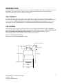
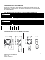
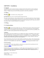
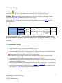
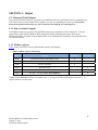
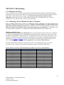
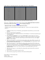
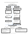
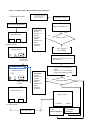
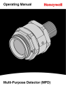
MILLENNIUM II
Combustible Gas Sensor
Catalytic Bead Sensor
User Manual
Model: SC310X-100-ASSY
Part Number: MAN-0084 Rev 4
August 27, 2010
IMPORTANT INFORMATION
This manual is for informational purposes only. Although every effort has been made to ensure the correctness
of the information, technical inaccuracies may occur and periodic changes may be made without notice. Net
Safety Monitoring Inc. assumes no responsibility for any error contained within this manual.
If the products or procedures are used for purposes other than as described in the manual, without receiving
prior confirmation of validity or suitability, Net Safety Monitoring Inc. does not guarantee the results and
assumes no obligation or liability. No part of this manual may be copied, disseminated or distributed without the
express consent of Net Safety Monitoring Inc.
Net Safety Monitoring Inc. products are carefully designed and manufactured from high quality components and
can be expected to provide many years of trouble free service. Each product is thoroughly tested, inspected and
calibrated prior to shipment. Failures can occur which are beyond the control of the manufacturer. Failures can
be minimized by adhering to the operating and maintenance instructions herein. Where the absolute greatest of
reliability is required, redundancy should be designed into the system.
WARRANTY
Net Safety Monitoring Inc warrants this sensor against defective parts and workmanship for a period of 5 years
from the date of shipment. No other warranties or liability, expressed or implied, will be honoured by Net Safety
Monitoring Inc. Contact Net Safety Monitoring Inc. or an authorized representative for details.
We welcome your input at Net Safety Monitoring Inc. If you have any comments please contact us at the
telephone number or address below or visit our web-site, www.net-safety.com/, and complete our on-line
customer survey.
If further language translation for this manual is required please contact:
CONTACT INFORMATION
Net Safety Monitoring Incorporated
Corporate Headquarters
2721 Hopewell Place NE
Calgary, AB Canada T1Y 7J7
MAN-0084 Rev 4 Catalytic Bead Sensor
August 27, 2010
Net Safety Monitoring Inc
Direct: (403) 219-0688
Facsimile: (403) 219-0694
E-mail: [email protected]
Web-site: www.net-safety.com/
TABLE OF CONTENTS
INTRODUCTION .................................................................................................................................................................. 5 THE PRODUCT ................................................................................................................................................................. 5 THE MANUAL.................................................................................................................................................................... 5 Transmitter and Sensor Enclosure Dimensions .............................................................................................................. 6 SECTION 1: Plan .................................................................................................................................................................. 7 1.1 Locate Sensor ................................................................................................................................................................ 7 1.2 Sensor Non-Separated/direct mounting ......................................................................................................................... 7 1.3 Sensor Separated/remote mounting ............................................................................................................................... 7 SECTION 2: Installation ...................................................................................................................................................... 8 2.1 Unpack........................................................................................................................................................................... 8 2.2 Mount............................................................................................................................................................................. 8 2.3 Wiring ............................................................................................................................................................................ 8 2.3.1 Field Installation .................................................................................................................................................... 8 Earth Grounding ................................................................................................................................................................. 8 2.3.2 Sensor Wiring ........................................................................................................................................................ 9 2.3.3 Installation Checklist ............................................................................................................................................. 9 SECTION 3: Operation ...................................................................................................................................................... 10 3.1 Configuration Settings ................................................................................................................................................. 10 3.2 Sensor Power Up ......................................................................................................................................................... 10 3.3 Sensor Communication ................................................................................................................................................ 10 3.4 SensorGuard ................................................................................................................................................................ 10 SECTION 4: Output ........................................................................................................................................................... 11 4.1 Alarm and Fault Outputs ............................................................................................................................................. 11 4.1.1 Other Available Outputs ...................................................................................................................................... 11 4.1.2 Modbus registers .................................................................................................................................................. 11 SECTION 5: Maintaining.................................................................................................................................................... 12 5.1 Calibration Procedure ................................................................................................................................................. 12 5.1.1 Calibrating with the Millennium II Basic Transmitter. ........................................................................................ 12 5.1.2 Calibrating with the Millennium II Transmitter................................................................................................... 16 5.1.3 Cross sensitivity ................................................................................................................................................... 20 5.2 Sensor Replacement Procedure ................................................................................................................................... 20 5.3 Troubleshooting ........................................................................................................................................................... 21 5.4 Storage......................................................................................................................................................................... 21 5.5 Spare Parts / Accessories ............................................................................................................................................ 21 5.6 How to Return Equipment ........................................................................................................................................... 22 3
MAN-0084 Rev 4 Catalytic Bead Sensor
August 27, 2010
Net Safety Monitoring Inc.
Appendix ............................................................................................................................................................................... 23 Appendix A: Electrostatic Sensitive Device (ESD) ............................................................................................................ 23 Appendix B: Resistance Table ........................................................................................................................................... 24 Appendix C: Millennium II Catalytic Bead Sensor Specifications .................................................................................... 25 4
MAN-0084 Rev 4 Catalytic Bead Sensor
August 27, 2010
Net Safety Monitoring Inc.
INTRODUCTION
Catalytic Bead (SC310) combustible gas sensors are designed specifically for use with any Millennium II series
transmitters. These state of the art “Smart” sensors are both versatile and reliable for fast, accurate and
continuous monitoring of gases in extreme environments.
THE PRODUCT
The sensor assembly consists of a factory sealed explosion proof enclosure (housing) rated for hazardous
locations and a replaceable combustible sensor module. This sensor should only be used with the Millennium II
series transmitters (Millennium II Basic Transmitter and the Millennium II Transmitter). If the sensor is
connected to any other model transmitter, it will not function and may result in the sensor being damaged.
THE MANUAL
This manual has been designed to ensure the sensor is set-up, operated and maintained properly. It outlines
specific details of the Catalytic Bead sensor and addresses calibration procedures using the Millennium II
Basic Transmitter and the Millennium II Transmitter. If you encounter any problems, see the
troubleshooting section of this manual or contact your local representative.
Figure 1: Sensor Dimensional Drawing
Measurements are in inches and millimeters (mm).
External Grounding Point
0.75” (19 mm)
1.25“ ( 31.75mm)
4.375” (111mm)
“ (119mm)
“
(66mm)
2.9”
(74mm)
5
MAN-0084 Rev 4 Catalytic Bead Sensor
August 27, 2010
Net Safety Monitoring Inc.
Transmitter and Sensor Enclosure Dimensions
The tables below give the enclosure (housing) dimensions of the Millennium II Transmitter with sensor and
Millennium II Basic Transmitter with sensor. Both transmitter and sensor enclosures are offered in Aluminum
(AL) and Stainless Steel (SS).
Table 1: Millennium II enclosure and sensor dimensions (A through H) in Inches(in) and Millimeters(mm)
Millennium II transmitter
enclosure
Transmitter & sensor(AL)
Transmitter & sensor(SS)
A
in
6.3
5.9
B
mm
160
150
in
5.6
5.1
C
mm
142
130
in
5.4
4.6
D
mm
137
117
in
9.7
8.9
E
mm
246
226
in
6.0
6.0
F
mm
152
152
in
5.7
5.8
G
mm
145
147
in
2.6
2.6
H
mm
66
66
in
2.9
2.9
mm
66
66
in
2.9
2.9
mm
74
74
Table 2: Millennium II Basic enclosure (or junction box enclosure) and sensor dimensions (A through J) in
Inches(in) and Millimeters(mm)
Millennium II Basic &
sensor
Transmitter & sensor(AL)
Transmitter & sensor(SS)
in
4.8
4.7
Table 2(cont’d)
Millennium II Basic &
sensor
Transmitter & sensor(AL)
Transmitter & sensor(SS)
in
3.0
2.8
A
B
mm
122
119
in
3.6
3.6
mm
76
71
in
9.0
8.9
I
C
mm
91
91
in
3.6
3.6
D
mm
91
91
in
4.8
4.7
E
mm
122
119
in
5.1
5.1
F
mm
130
130
in
0.3
0.3
G
mm
7.6
7.6
in
2.6
2.6
H
J
mm
229
226
Figure 2: Dimensional drawing for sensor with Millennium II series transmitters
Millennium II Basic Transmitter with sensor
Millennium II Transmitter with sensor
A
E
A
B
F
B
D
C
I
C
E
J
R 0.157”
(3.98mm)
D
F
4.1” (AL)
(103.0mm)
3.8” (SS)
(97.0mm)
G
G
H
H
6
MAN-0084 Rev 4 Catalytic Bead Sensor
August 27, 2010
Net Safety Monitoring Inc.
mm
74
74
SECTION 1: Plan
1.1 Locate Sensor
Prior to the installation process, a plan should be developed for placement of the sensor. Although there are no
absolute rules determining the quantity of detectors or location of a sensor, the following points should be
considered when planning the installation.
•
•
•
•
•
•
Carefully locate the sensor in an area where gases may potentially accumulate. (Remember, light gases
tend to rise and heavy gases tend to accumulate in low areas).
Use redundant systems to enhance protection and reliability.
Consider the air movement patterns within the facility.
Consider the construction of the facility such as trenches where heavy gases or peaks where light gases
may accumulate.
Seek advice from experts knowledgeable about the primary gas to be detected.
Use common sense and refer to the regulatory publications that discuss guidelines for your industry.
1.2 Sensor Non-Separated/direct mounting
The sensor is attached directly to a transmitter and placed in the appropriate location for detecting the gas in
question (target gas).
Figure 3: Locating Sensor
1.3 Sensor Separated/remote mounting
The sensor should always be connected to a certified
junction box when separated from transmitter. The
transmitter is located near eye-level for easy access and the
sensor is mounted where gas is likely to accumulate. A
calibration cup is clipped onto the bottom of the sensor
enclosure and the calibration tubing is attached to the
calibration cup and runs back to a convenient place for
applying calibration gas, eliminating the need to access the
sensor directly. Calibration gas can then be applied from
ground level.
To compensate for the effect of distance when remotely
calibrating, in separation configuration, decrease the
tubing diameter or increase the calibration gas flow rate
between the gas canister and sensor. On initial install,
always confirm tubing run is not affecting calibration.
Calibrate the sensor using tubing run and then confirm
readings directly at sensor by applying calibration gas and
comparing the output results. Readings should be accurate
to the calibration gas concentration used.
7
MAN-0084 Rev 4 Catalytic Bead Sensor
August 27, 2010
Net Safety Monitoring Inc.
SECTION 2: Installation
2.1 Unpack
Carefully remove all the components from the packaging and check them against the enclosed packing list.
Inspect all components for any obvious damage such as broken or loose parts. If you find any components
missing or damaged, notify your local Net Safety representative or the factory immediately.
2.2 Mount
Warning
Never install the sensor pointing upwards.
Recommendation: The sensor should be installed pointing downwards.
The sensor is mounted directly to either transmitter enclosure or to a separation junction box enclosure through a
¾” NPT conduit entry. Both the transmitter and junction box enclosures have mounting holes to allow mounting
to a wall or pole as desired. Mounting kit hardware is required when mounting to a pole. Contact your local Net
Safety Representative for detailed information on mounting kits.
2.3 Wiring
2.3.1 Field Installation
Warning
Wiring codes and regulations may vary. ATEX requires that supply connection wiring must be
rated at least 5°C above the maximum ambient temperature of 85°C. Wiring must comply with all applicable
regulations relating to the installation of electrical equipment in a hazardous area and is the responsibility of the
installer. If in doubt, consult a qualified official before wiring the system.
Guidelines
When separating sensor from transmitter, the use of shielded cable is highly recommended for sensor wiring to
protect against interference caused by extraneous electrical or electromagnetic ‘noise’. To meet IEC 61000-1,
IEC 61000-4 EMI, follow recommendations on cable choice and guidelines in the specific Millennium II series
transmitter manual (MAN-0082 or MAN-0076). In applications where the wiring is installed in conduit, the
conduit must not be used for wiring to other electrical equipment.
The maximum distance between the sensor and transmitter is limited by the resistance of the connecting wiring,
which is a function of the gauge of the wire being used. Net Safety recommends that sensor separation distance
should not be more than 2000 ft with 16 AWG wire. See Appendix B for wire gauges and resistance values.
Earth Grounding
An external ground is required. One method is to connect the external ground to the grounding point on the
enclosure. See Figure 1 for grounding connection location.
Conduit Entry
Sensors are mounted directly to transmitters via ¾” NPT conduit entries through which wires are connected to
terminals. Sensors may also be mounted remotely from transmitters using certified junction boxes with
designated terminals. Transmitter and junction box enclosures are shipped with one stopping plug fitted and
tightened to a ¾” NPT conduit entry.
8
MAN-0084 Rev 4 Catalytic Bead Sensor
August 27, 2010
Net Safety Monitoring Inc.
2.3.2 Sensor Wiring
Warning
Do not open enclosures in a classified area (Do not open when an explosive atmosphere may
be present). Ensure the power to the transmitter is switched off before connecting sensor wires.
Warning
Avoid touching electronic components, as they are susceptible to electrostatic discharge
(ESD). Refer to Appendix A, “Electrostatic Sensitive Device (ESD)”.
Connect sensor wires to the sensor terminals in the applicable transmitter. Refer to the Table 3 for sensor
terminal definitions.
Table 3: Sensor wires and Millennium II series Terminal definitions
Sensor Terminals Sensor Wire White Red Blue Black Green Marked +Vdc Sig A Sig B COM Function 10.5 ‐ 32Vdc A B Common/Supply Ground Earth Ground NOTE: When separating sensor from transmitter using Net Safety separation kit, refer to Multi-purpose
Junction Box Manual (MAN-0081) for terminal designations. Always ensure that the transmitter is supplying
the required voltage across sensor power terminals inside junction box. Refer to table above for sensor voltage
requirements.
2.3.3 Installation Checklist
Prior to operation, it is important to do the following:
•
•
•
•
•
•
•
•
•
•
Ensure transmitter and sensor are properly and firmly mounted.
Ensure that stopping plug is tightened to unused conduit entry.
Ensure transmitter and sensor are not being obstructed; transmitter and sensor are accessible and target
gas is not inhibited from reaching sensor.
Remove sensor red protective plastic cap/cover from sensor mouth.
If IP filters are being used/fitted to sensor, check for damage or debris. Refer to specific IP filter
instruction guide (MAN-0109).
If calibration cup (splash guard) is being used/fitted to sensor, ensure a snug fit.
Ensure adherence to applicable local guidelines and requirements on wiring and sealing of equipment in
hazardous and non-hazardous areas.
Ensure that proper shielding and grounding practices are adhered to, and local codes are being followed.
Check system operational voltage and conditions. See Table 3 and Appendix C.
Check wiring at all termination and junction points; wiring at transmitter terminals, junction box and at
power supply. See Table 3 above and specific transmitter manual.
9
MAN-0084 Rev 4 Catalytic Bead Sensor
August 27, 2010
Net Safety Monitoring Inc.
SECTION 3: Operation
3.1 Configuration Settings
All configuration settings are accessed through the Millennium II series transmitters. This is done by setting DIP
switches on the Millennium II Basic Transmitter and by selecting menu options in the Millennium II
Transmitter. Some configurations are done by the HART communicator on Analog /HART transmitter models.
Refer to Section ‘5.1.1: Calibrating with the Millennium II Basic Transmitter’ and Section ‘5.1.2: Calibrating
with the Millennium II Transmitter’ for information on selecting the target gas. Also see the relevant transmitter
manual for information on Modbus settings.
3.2 Sensor Power Up
When power is applied to sensors by transmitters, a 30 second warm-up routine will begin, whereby sensors are
automatically tested to ensure proper functioning. Refer to the Millennium II Basic Transmitter manual (MAN0082) or the Millennium II Transmitter manual (MAN-0076) for status indications during this period. It is
recommended that these sensors be powered up for 24 hours prior to the first calibration.
3.3 Sensor Communication
SC310 sensors use a proprietary protocol to communicate with the Millennium II series transmitters. These
sensors should never be connected to any device other than the Millennium II series transmitters. Selected DIP
switches and menu options allow communication between transmitters and sensors. Configuration settings are
stored in the sensor’s memory. Incorrect settings will cause sensors not to communicate properly with
transmitters. If any problems develop see troubleshooting section.
3.4 SensorGuard
SensorGuard is a proprietary firmware feature that protects the pellistor sensor from the damage and/or response
shift commonly caused by exposure to high concentrations of combustible gas. With this feature, repeated or
lengthy exposure to high gas concentrations has negligible effect on sensor performance. Sensor life is
prolonged and calibration frequency is reduced. This does not eliminate the necessity of periodic sensor
response checks which should be performed as part of an effective maintenance schedule.
If a gas signal exceeds 100% LEL, the Millennium II series transmitters will latch the output of the sensor at 20
mA and the display of the Millennium II Transmitter will flash ‘100% LEL’ continually until power is recycled
or a manual reset is initiated. Refer to ‘manual reset’ in the Millennium II Basic Transmitter manual (MAN0082) or the Millennium II Transmitter manual (MAN-0076).
If the gas signal exceeds 105% LEL, the sensor will deactivate the sensing element to protect it from extreme
drift or damage caused by high gas concentrations. This protective feature extends the useful lifetime of the
sensor and reduces or eliminates disruption of its calibration. As an extra safety precaution, the system should be
checked for accuracy after such over-range exposure and if necessary re-calibrated. The system will need to be
reset to clear the latched output.
10
MAN-0084 Rev 4 Catalytic Bead Sensor
August 27, 2010
Net Safety Monitoring Inc.
SECTION 4: Output
4.1 Alarm and Fault Outputs
Sensor alarm and fault outputs are generated by the Millennium II series transmitters based on communication
with sensors, however some output values, registers, etc, may vary depending on sensor type. The default
alarm levels (point) for the sensor are: 20 % for the low level and 40 % for the high level.
4.1.1 Other Available Outputs
All available outputs are associated with the Millennium II series transmitters. These outputs are: 4-20 mA
output, Relay output, RS 485 Modbus (RTU) output and HART Communication output. Refer to the
Millennium II Basic Transmitter manual (MAN-0082) or the Millennium II Transmitter manual (MAN-0076)
for more information.
4.1.2 Modbus registers
Table 4 below, shows the user accessible Modbus registers and meaning.
Table 4: Modbus registers and meaning
Reg #
Meaning
Readable
Writeable
40001
Concentration value as calculated by sensor
X
40002
Sensor status
X
40003
Sensor Temperature
X
40101
Resets the sensor
X
40102
Initialize zero & span *( to calibrate sensor, enter channel #)*
X
40104
Zero only *( to zero sensor, enter channel #)*
X
* Note: For the Millennium II Basic Transmitter enter ‘1’ in register 40102 to calibrate the sensor and ‘1’ in
register 40104 to zero the sensor.
11
MAN-0084 Rev 4 Catalytic Bead Sensor
August 27, 2010
Net Safety Monitoring Inc.
SECTION 5: Maintaining
5.1 Calibration Procedure
There are specific steps to be followed when calibrating with the Millennium II Basic and the Millennium II
Transmitters. These steps should be followed if accurate results are to be obtained. The calibration of Catalytic
Bead sensors requires the presence of oxygen. An air balanced calibration gas should be used for
calibration, otherwise these sensors will not calibrate properly. It is recommended that these sensors be
calibrated every 3 months (90 days) to ensure proper functioning.
5.1.1 Calibrating with the Millennium II Basic Transmitter.
When a Catalytic Bead sensor is fitted to a Millennium II Basic Transmitter, the default setting of the
transmitter’s DIP Switch 2 Positions is as follows: Position 1 ON and Positions 2, 3 and 4 all OFF. These
DIP Switch positions should not be altered. When calibrating, follow the normal calibration procedure below
using 50% span of the specific LEL gas to be detected (target gas) for calibrations. If calibration is not
successful perform a manual reset. See Millennium II Basic Manual (MAN-0082) for manual reset.
Methane as calibration gas:
If only Methane gas is available as calibration gas, then a specific Correction Factor (“K Factor”) relating to
the target gas (non-Methane) has to be manually entered using the HART Communicator. This feature is only
available on Analog/HART Transmitter Models. The appropriate Correction Factor is dependent on the Lower
Explosive Limit (LEL) of the desired target gas as specified by the performance standard(s) applicable at the
installation site. Table 5 and Table 6 provide Correction Factors for common gases and their respective LEL
values. Use 50% span Methane gas with the appropriate % by volume as indicated below.
The tables below outline the primary detectable gases of the sensor. Multiple other gases are however,
detectable. Please contact your representative regarding any gases not included in tables below.
Table 5: K-Factors for ISA (N. American) LEL values (Calibrate with 2.5% by volume Methane)
Gas
Propane
n-Butane
Isobutylene
Hydrogen
Ethane
Pentane
Hexane
Heptane
Ethylene
Propylene
Methanol
LEL
2.1% Volume
1.8% Volume
1.8% Volume
4.0% Volume
3.0% Volume
1.4% Volume
1.2% Volume
1.1% Volume
2.7% Volume
2.4% Volume
6.7% Volume
Correction Factor
1.8
2.0
2.1
1.2
1.4
2.2
2.3
2.7
1.5
1.5
1.2
Ethanol
3.3% Volume
1.7
12
MAN-0084 Rev 4 Catalytic Bead Sensor
August 27, 2010
Net Safety Monitoring Inc.
Table 6: K-Factors for IEC (European) LEL values (Calibrate with 2.2% by volume Methane)
Gas
Propane
n-Butane
Isobutylene
Hydrogen
Ethane
Pentane
Hexane
Heptane
Ethylene
Propylene
Methanol
Ethanol
LEL
1.7% Volume
1.4% Volume
1.8% Volume
4.0% Volume
2.5% Volume
1.4% Volume
1.0% Volume
1.1% Volume
2.3% Volume
2.0% Volume
5.5% Volume
3.1% Volume
Correction Factor
2.0
1.9
1.7
1.2
1.5
1.9
2.5
2.4
1.6
1.6
1.3
1.6
Note: For other gases and Correction Factors, please contact the manufacturer (factory).
If the sensor’s configuration setting is setup correctly as desired, refer to Millennium II Basic Transmitter
calibration procedure below and/or Figure 4 before attempting calibration.
Millennium II Basic Transmitter Normal Calibration Procedure:
Calibrations may be performed either by using the magnet (non – intrusive) or by using the push button
(intrusive).
1. Confirm successful power up of Transmitter, (green blip/blink of status LED every second: no fault
indicated).
2. Bypass any output alarms (recommended).
3. For analog model connect a standard current meter to the transmitter’s Test Jacks (not required but gives
visual confirmation).
4. Press and hold the “push button” (or activate the “Reed switch” using the magnet) for at least 15
seconds, the status LED flashes green fast, and then goes solid green (first solid green). Keep holding
“push button” or magnet, after which, status LED goes solid red. When this occurs, release “push
button” or remove magnet.
5. When the current output is 3 mA (indicated by analog models) and the Status LED is once again solid
green (second solid green), apply zero gas (clean air). Recommendation: Flow ZERO AIR at a rate of
0.5 liter per minute or more to the sensor.
6. When the current output is 3.3 mA (indicated by analog models) and the Status LED is flashing red,
apply specific calibration gas (50% of full span). Recommendation: Flow span gas at a rate of 0.5 liter
per minute to the sensor for direct sensor calibrations. If sensor is remotely mounted and long tubing run
is used, increase gas flow rate (e.g.1.0 liter per minute) to ensure tubing length does not affect
calibration results.
7. When the current output is 3.6 mA (indicated by analog models) and the Status LED is solid green,
remove the gas.
8. Apply zero gas (clean air) again to purge the system.
9. After the sensor is purged of gas, the detector will return to normal operation.
13
MAN-0084 Rev 4 Catalytic Bead Sensor
August 27, 2010
Net Safety Monitoring Inc.
Note: When calibrating with the Millennium II Basic Transmitter always use 50% span gas (half the scale).
Calibration gas MUST be air balanced for SC310 sensors. Calibration instructions are also accessed using
the HART Communicator with the Analog/HART model transmitter. For HART Menu Structure/Tree, see
Millennium II Basic transmitter manual (MAN-0082).
Zero Calibration Option:
This option is useful if the sensor’s zero point has drifted as a result of a change in the ambient conditions.
The “Zero” calibration option is selected if a sensor is only being zeroed (this not a complete calibration).
The application of span gas is not required, as only the sensor’s zero point is adjusted. Ensure that no
contaminants are present, if the surrounding air is to be used for Zeroing. If Zero calibration is needed, at step 4
above, hold the push button or activate Reed switch (for 6-9 seconds) using the magnet, until the status LED
goes solid green, and then release the switch. Zero calibration will begin immediately.
See Figure 4: Calibration Flow chart for Millennium II Basic Transmitter on next page for additional
reference.
14
MAN-0084 Rev 4 Catalytic Bead Sensor
August 27, 2010
Net Safety Monitoring Inc.
Figure 4: Calibration Flow chart for Millennium II Basic Transmitter
Calibration Procedure
ZERO Calibration
Activate/Hold *calibration
switch* for 6 -9 seconds.
FULL Calibration
Activate/Hold *calibration switch* for 10-15
seconds. Keep holding through first solid
Green until status LED is Solid Red.
Status LED: Solid Red
Status LED: Flashes fast
Green
Status LED: Solid Green
Release push button
/magnet
Status LED: Solid Green
Current output: 3.0 mA
indicated by Analog
models
Release push button
/magnet
Apply air from canister or use
clean ambient air to perform ‘zero’
Apply air from canister or use
clean ambient air to perform ‘zero’
Status LED: Flashing Red
Current output: 3.3 mA
indicated by Analog models
Apply 50% span target gas to perform ‘span’
NO
Calibration successful?
Status LED: Solid Green.
YES
Current output: 3.6 mA
indicated by Analog models
Calibration Failed. Status LED:
Alternating Red/Green flashes.
Current output: 3.0/3.3 mA indicated by Analog
models.
Perform manual reset. Refer to “manual reset” in MII
Basic transmitter manual (man-0082).
Repeat calibration procedure.
Note: * See the Millennium II Basic transmitter manual (MAN-0082) when locating calibration
switch MAN-0084
(push button) or magnetic
switch.
Rev 4 Catalytic
Bead Sensor
August 27, 2010
Net Safety Monitoring Inc.
•
Remove gas and purge system with clean air from canister
upon completion of Full calibration procedure, then
remove air canister.
•
Remove air canister after Zero calibration procedure if an
air canister was used.
15
5.1.2 Calibrating with the Millennium II Transmitter.
The following procedures are specific to this controller and should be followed to ensure accurate calibration
and detection of gases. The transmitter also offers some flexibility in the use of calibration gas. If the calibration
gas available is not 50% span gas, the transmitter will allow calibration to be performed with calibration gas
within the range of 10- 60% span gas. For the most accurate calibration however, the calibration gas value
should be within 40-60% of the full scale range. To select the calibration gas value, enter the transmitter’s main
menu and select ‘cal. gas value’ and enter the value. Refer to MAN-0076 when navigating through menu
options.
Configuration for the target calibration gas:
If a calibration gas cylinder of the desired target gas (Methane or otherwise) is available, refer to the steps below
to first configure the sensor for the target gas.
1. Enter the Main menu, first by pressing any key to get the “enter main menu” prompt, then press menu
button 1(Reed switch 1) to select “yes.”
2. Select the up arrow key (menu button 1 or Reed switch 1) or down arrow key (menu button 2 or Reed
switch 2), until “Select Gas Type” option is displayed.
3. Select the enter key (Menu button 3 or Reed switch 3) to enter the option and ensure the default setting,
CH1: No correction & CH2: No correction is being displayed, then exit and proceed to the calibration
procedure; calibrate with the specific target gas (detectable gases listed in Table 5 or Table 6).
4. If the “custom” option is being displayed at step 3, select Menu button 3 or Reed switch 3 and then use
Menu button 2 or Reed switch 2 to navigate to “No correction”. Select “No correction” option with
Menu button 3 or Reed switch 3.
5. Use the navigation keys along with Menu button 3 or Reed switch 3until the main menu is completely
exited.
Note: Use the specific gas to be detected (with the same calibration value as that selected in the transmitter’s
menu under “Cal. gas value”) for calibrating the sensor.
Configuration for Methane as the calibration gas:
If only methane is available as calibration gas, then select “Custom” in the controller’s main menu under ‘select
gas type’. Enter the specific K-Factor from Table 5 or Table 6 above. Follow the steps below in entering K
Factor.
1. Enter the Main menu, first by pressing any key to get the “enter main menu” prompt, then press menu
button 1(Reed switch 1) to select “yes.”
2. Select the up arrow key (menu button 1 or Reed switch 1) or down arrow key (menu button 2 or Reed
switch 2), until “Select Gas Type” option is displayed.
3. Select Menu button 3 or Reed switch 3 then use and Menu button 2 or Reed switch 2 to navigate to
“Custom”. Select “Custom” with Menu button 3 or Reed switch 3.
4. To configure the K Factor option/sub menu, select Menu button 3 or Reed switch 3 again.
16
MAN-0084 Rev 4 Catalytic Bead Sensor
August 27, 2010
Net Safety Monitoring Inc.
5.
“Enter K Factor” will be displayed with an existing K-Factor value. Use menu button 1 or Reed switch 1
to increase the displayed digits and use (menu button 2 or Reed switch2) to navigate across digits.
6. When the desired K Factor value is entered as desired (taken from Table 5 or Table 6), exit by selecting
“Exit” with Menu button 3 or Reed switch 3.
7. Use the navigation keys along with Menu button 3 or Reed switch 3 until the main menu is completely
exited.
Note: Use the available Methane gas (with the same calibration value as that selected in the transmitter menu
under Cal. gas value) for calibration the sensor.
Refer to Millennium II Transmitter calibration procedure below and/or Figure 5 before attempting
calibration.
Millennium II Transmitter Normal (Full) Calibration Procedure:
If the sensor’s configuration setting is setup correctly as desired, follow the steps below for Full Calibration /
Normal Calibration Procedure. Note that if a calibration is not successful the message “Span failed” will be
displayed and a manual reset will have to be initiated. Refer to Millennium II Transmitter manual (MAN-0076)
for manual reset.
1. Enter the main menu, first by pressing any key to get the “enter main menu” prompt, then press/select
menu button 1 or Reed switch 1 to select “yes.”
2. When “Calibrate Sensor?” is displayed, select the enter key (menu button 3 or Reed switch 3).
3.
When “Calibrate Sensor #1?” is highlighted, press the enter key (menu button 3 or Reed switch 3) if
this is the sensor to be calibrated or,
4. If Sensor #2 is to be calibrated, select the down arrow key (menu button 2 or Reed switch 2) to scroll to
“Calibrate Sensor #2?”
5. When the desired sensor to be calibrated (1 or 2) is highlighted, activate the enter key (menu button 3 or
Reed switch 3).
6. Select “YES” (menu button 1 or Reed Switch 1) to confirm the selection.
7. Apply clean air when “Apply Clean Air” is displayed, then select “Z & Span” using (menu button 1 or
Reed Switch 1) for normal calibration. “Setting zero” will be displayed as the sensor is being zeroed.
(Ensure no contaminant gases are present if ambient air is being used).
8. Apply 50% calibration gas (or % Cal. gas value chosen in menu option) when prompted.
Recommendation: Flow span gas at a rate of 0.5 liter per minute to the sensor for direct calibrations. If
sensor is remotely mounted and long tubing run is used, increase gas flow rate (e.g. 1.0 liter per minute)
to ensure tubing length does not affect calibration results.
9. The display will show “Spanning” with the gas value (%LEL ) as the gas is detected.
17
MAN-0084 Rev 4 Catalytic Bead Sensor
August 27, 2010
Net Safety Monitoring Inc.
10. Remove the calibration gas when “Remove Cal Gas” is displayed.
11. “Cal Complete” will be displayed when calibration is complete.
12. Apply zero gas (clean air) to purge system.
Note: Calibration gas MUST be air balanced. Calibration instructions are also accessed using the HART
Communicator with the single channel Millennium II Transmitter model.
Zero Calibration Option:
This option is useful if the sensor’s zero point has drifted as a result of a change in the ambient conditions.
The “Zero” calibration option is selected if the sensor is only being zeroed (this not a complete calibration)
It does not require the application of span gas, as only the sensor’s zero point is adjusted. Ensure that no
contaminants are present, if the surrounding air is to be used for Zeroing. If Zero calibration is needed, at step 7
above, select ‘Zero’ using (menu button 3 or Reed Switch 3) and use clean ambient air or air from canister to
calibrate.
See Figure 5: Calibration Flow chart for Millennium II Transmitter on next page for additional
reference. The chart shows calibration steps for channel 1. Calibration steps for channel 2 are similar.
18
MAN-0084 Rev 4 Catalytic Bead Sensor
August 27, 2010
Net Safety Monitoring Inc.
Figure 5: Calibration Flow chart for Millennium II Transmitter
Calibration Procedure
Purge system with clean
air from canister, then
remove air canister
Calibration complete
Activate any menu button
Remove Calibration Gas
Enter Main Menu
YES
NO
Activate menu button 1
Span Failed.
Perform
manual reset.
See MII
transmitter
manual
(MAN-0076).
Repeat
calibration
procedure.
YES
NO
Span successful?
CH1: Spanning
LEL reading
Calibrate Sensor?
Apply 50% Span gas (or Cal. gas
value chosen)
Activate menu
button 3 to select
Calibrate Sensor #1?
•
Calibrate Sensor #2?
•
EXIT
Activate menu button
3 to select
Zero Failed.
Perform
manual reset.
See MII
transmitter
manual
(MAN-0076).
Repeat
calibration
procedure.
Remove air canister if air canister was used
in Zero calibration. Zero calibration
complete.
Remove air canister in Full calibration
procedure and continue to span step
YES
NO
Zero successful?
Calibrate Sensor #1?
Apply Clean Air
YES
NO
Z & SPAN
ZERO
Activate menu button 1
MAN-0084 Rev 4 Catalytic
Bead
Sensor
Apply air from
canister
August 27, 2010 or use clean ambient
Net Safety Monitoring Inc.
Activate menu button 1
to select
Activate menu button 3
to select ZERO
FULL Calibration
Calibration
19
5.1.3 Cross sensitivity
The SC310 sensor will react to airborne materials that burn or explode in oxygen atmospheres, such as gaseous
hydrocarbons. Certain compounds, including Halogen-containing hydrocarbons, can reduce sensor response. In
some instances this reduction in response is reversible and the sensor will operate normally when such a
compound or gas is removed. Exposure to organic phosphates, esters and Silicon-containing compounds will
"poison" the sensor, resulting in an irreversible loss in sensitivity. For more information, please contact the
manufacturer.
5.2 Sensor Replacement Procedure
Sensors are pre-calibrated at the factory but field calibration must be performed as part of commissioning.
When a calibration can no longer be performed or the sensor is not operating properly the sensor module may
need to be replaced. Refer to steps below for replacing sensor module.
Warning Do not open enclosure in a classified area.
Note: Components are ESD sensitive, as a result all ESD rules and procedures should be observed. See
Appendix A for ESD guidelines.
To replace the sensor module:
1. Remove power from sensor.
2. Remove the locking ring by loosening the set crews with 1.5 mm Allen Key tool.
3. Remove the bottom part of the sensor enclosure by turning in a counter clockwise rotation to expose
sensor module.
4. Using the Teflon pull tab, pull sensor module straight down out of the sensor enclosure until it is
completely removed from the enclosure.
5. Align replacement sensor module with pins inside top section of the enclosure base and push on outer
plastic ring until sensor is seated properly. DO NOT PUSH ON CENTER ELEMENT.
6. Install and hand-tighten the bottom part of the sensor enclosure by turning in a clockwise direction.
7. Install the locking ring by tightening the set screws with 1.5 mm Allen Key tool.
8. Restore power to sensor via transmitter.
20
MAN-0084 Rev 4 Catalytic Bead Sensor
August 27, 2010
Net Safety Monitoring Inc.
5.3 Troubleshooting
Sensors and controllers / transmitters are not designed to be repaired in the field. If problems should develop,
first check for faulty wiring, confirm proper voltage to sensor, and attempt a calibration. If problems persist,
please contact Net Safety’s Service Department first by phone to try and resolve any issues. If issues cannot be
resolved, please follow the procedure on next page, on ‘how to return equipment.’
5.4 Storage
The sensor and its electronic components/parts should be stored in locations free from dust and moisture. The
storage temperature should be well within the limits of the certified temperatures of the equipment. See
Appendix C for certified temperatures.
5.5 Spare Parts / Accessories
Table 7: Available Spare Parts
Description
Net Safety Part Number
Calibration Cup / Splash Guard
CCS-1
Separation Kit
JB-MPD-A (aluminum) or JB-MPD-S (316 stainless steel)
Dust Filter Assembly
DSC-1
Replacement Cat Bead Sensor
SC310-100
IP66/67 Hydrophobic Filter
IPF-001
21
MAN-0084 Rev 4 Catalytic Bead Sensor
August 27, 2010
Net Safety Monitoring Inc.
5.6 How to Return Equipment
A Material Return Authorization number is required in order to return equipment. Please contact Net Safety
Monitoring at (403) 219-0688, before returning equipment or consult our Service Department to possibly avoid
returning equipment.
If you are required to return equipment, include the following information:
1. A Material Return Authorization number (provided over the phone to you by Net Safety).
2. A detailed description of the problem. The more specific you are regarding the problem, the quicker our
Service Department can determine and correct the problem.
3. A company name, contact name and telephone number.
4. A purchase order, from your company, authorizing repairs or request for quote.
5. Ship all equipment, prepaid to:
Net Safety Monitoring Inc.,
2721 Hopewell Place NE,
Calgary, Alberta, Canada, T1Y 7J7
6. Mark all packages: RETURN for REPAIR.
7. Waybills, for shipment outside Canada, must state:
Equipment being returned for repair
All charges to be billed to the sender
Ensure a duplicate copy of the packing slip is enclosed inside the box indicating item 1 – 4 along with the
courier and account number for returning the goods.
Pack items to protect them from damage and use anti-static bags or aluminum-backed cardboard as protection
from electro-static discharge.
ALL equipment must be shipped prepaid. Collect shipments will not be accepted.
22
MAN-0084 Rev 4 Catalytic Bead Sensor
August 27, 2010
Net Safety Monitoring Inc.
Appendix
Appendix A: Electrostatic Sensitive Device (ESD)
Definition: Electrostatic discharge (ESD) is the transfer, between bodies, of an electrostatic charge caused by
direct contact or induced by an electrostatic field.
The most common cause of ESD is physical contact. Touching an object can cause a discharge of
electrostatic energy—ESD! If the charge is sufficient and occurs near electronic components, it can damage
or destroy those components. In some cases, damage is instantaneous and an immediate malfunction occurs.
However, symptoms are not always immediate—performance may be marginal or seemingly normal for an
indefinite period of time, followed by a sudden failure.
To eliminate potential ESD damage, review the following guidelines:
• Handle boards by metal shields—taking care not to touch electronic components.
• Wear grounded wrist or foot straps, ESD shoes or heel grounders to dissipate unwanted static energy.
• Prior to handling boards, dispel any charge in your body or equipment.
• Ensure all components are transported and stored in static safe packaging
• When returning boards, carefully package in the original carton and static protective wrapping
• Ensure ALL personnel are educated and trained in ESD Control Procedures
In general, exercise accepted and proven precautions normally observed when handling electrostatic sensitive
devices. A warning label is placed on the packaging, identifying product using electrostatic sensitive
semiconductor devices.
23
MAN-0084 Rev 4 Catalytic Bead Sensor
August 27, 2010
Net Safety Monitoring Inc.
Appendix B: Resistance Table
Distance
(Feet)
100
AWG #20
0.5mm2
1.02
AWG #18
0.8mm2
0.64
AWG #16
1.0mm2
0.40
AWG #14
2.0mm2
0.25
200
2.03
1.28
0.80
0.51
300
3.05
1.92
1.20
0.76
400
4.06
2.55
1.61
1.01
500
5.08
3.20
2.01
1.26
600
6.09
3.83
2.41
1.52
700
7.11
4.47
2.81
1.77
800
8.12
5.11
3.21
2.02
900
9.14
5.75
3.61
2.27
1000
10.20
6.39
4.02
2.53
1250
12.70
7.99
5.03
3.16
1500
15.20
9.58
6.02
3.79
1750
17.80
11.20
7.03
4.42
2000
20.30
12.80
8.03
5.05
2250
22.80
14.40
9.03
5.68
2500
25.40
16.00
10.00
6.31
3000
30.50
19.20
12.00
7.58
3500
35.50
22.40
14.10
8.84
4000
40.60
25.50
16.10
10.00
4500
45.70
28.70
18.10
11.40
5000
50.10
32.00
20.10
12.60
5500
55.80
35.10
22.10
13.91
6000
61.00
38.30
24.10
15.20
6500
66.00
41.50
26.10
16.40
7000
71.10
44.70
28.10
17.70
7500
76.10
47.90
30.10
19.00
8000
81.20
51.10
23.10
20.20
9000
91.40
57.50
36.10
22.70
10000
102.00
63.90
40.20
25.30
Resistance shown is one way. This figure should be doubled when determining closed loop resistance.
24
MAN-0084 Rev 4 Catalytic Bead Sensor
August 27, 2010
Net Safety Monitoring Inc.
Appendix C: Millennium II Catalytic Bead Sensor Specifications
SENSOR
Catalytic Bead
Performance
Power Consumption
(10.5 – 32 VDC) < 1.5WATT
Voltage Range
10.5 – 32 VDC
RFI, EMC, Immunity
RFI: 150 to 170 MHz and 450 to 470 MHz, 5W FM radio at 1 meter away; EMC: IEC 61000-1-4 and IEC
61000-4-3 Severity level 2
T50 < 5.5 sec
T60 < 6 sec
T90 < 12 sec
Response Time
Zero Drift
+/- 2% per month
Repeatability
+/- 1% LEL
Environmental
Temperature
Performance verified: -55°C to +85°C
Certified: -40°C to +75°C.
RH
0 – 99% RH
Metallurgy
Aluminum (AL6061) or Stainless Steel (316 SS)
Nema / IP Rating
NEMA 4X / IP 64
Weight
Aluminum (AL6061) enclosure: 0.4kg/1.0lbs,
Stainless Steel (SS316) enclosure: 1.4kg/3.5lbs
Separation
Up to 2000 feet / 600 meters with 16 AWG wires
Separation
Approvals
Approvals
Performance certified to FM6310, FM6320, CSA 22.2 No. 152, IEC/EN61779‐1, IEC/EN61779‐4, ANSI/ISA‐12.13.01 FM certification (Canada and US) Class 1, Div 1, Grps BCD, Zone 1, AEx/Ex d IIB+H2, T5,
IP64, Type 4X
FM ATEX: 0575 II2 G Ex d IIB+H2, T5, IP64 FM07ATEX0012X 25
MAN-0084 Rev 4 Catalytic Bead Sensor
August 27, 2010
Net Safety Monitoring Inc.
Net Safety Monitoring Inc. 2721 Hopewell Place NE, Calgary, AB Canada T1Y 7J7 1‐866‐FIREGAS (347‐3427) | ph. (403) 219‐0688 | fx. (403) 219‐0694 http://www.net‐safety.com | Email: nsmsales@net‐safety.com PRODUCT SERVICES CONTACT INFORMATION Telephone [ 8am ‐ 5pm MDT ]: (403) 769‐6074 | (403) 717‐8219 Fax: (403) 219‐0694 Email: productservices@net‐safety.com http://www.net‐safety.com/service/product_services.html MAN-0084 Rev 4 Catalytic Bead Sensor
August 27, 2010
Net Safety Monitoring Inc