1
INSTRUCTION MANUAL
VHF FM TRANSCEIVER/
UHF FM TRANSCEIVER
TK-280/ TK-380
800 MHz FM TRANSCEIVER/
900 MHz FM TRANSCEIVER
TK-480/ TK-481
KENWOOD CORPORATION
© B62-1483-00 (K)
09 08 07 06 05 04 03 02 01
THANK YOU
We are grateful you chose KENWOOD for your land
mobile radio applications. We believe this easy-to-use
transceiver will provide dependable communications to
keep personnel operating at peak efficiency.
KENWOOD transceivers incorporate the latest in
advanced technology. As a result, we feel strongly that
you will be pleased with the quality and features of this
product.
MODELS COVERED BY THIS MANUAL
• TK-280: VHF FM Transceiver
• TK-380: UHF FM Transceiver
• TK-480: 800 MHz FM Transceiver
• TK-481: 900 MHz FM Transceiver
NOTICES TO THE USER
◆ Government law prohibits the operation of unlicensed radio
transmitters within the territories under government control.
◆ Illegal operation is punishable by fine and/or imprisonment.
◆ Refer service to qualified technicians only.
SAFETY: It is important that the operator is aware of
and understands hazards common to the operation of
any transceiver.
EXPLOSIVE ATMOSPHERES (GASES, DUST, FUMES, etc.)
Turn off your transceiver while taking on fuel, or while parked in
gasoline service stations.
i
One or more of the following statements may be applicable:
FCC WARNING
This equipment generates or uses radio frequency energy. Changes
or modifications to this equipment may cause harmful interference
unless the modifications are expressly approved in the instruction
manual. The user could lose the authority to operate this equipment
if an unauthorized change or modification is made.
INFORMATION TO THE DIGITAL DEVICE USER REQUIRED BY THE FCC
This equipment has been tested and found to comply with the limits
for a Class B digital device, pursuant to Part 15 of the FCC Rules.
These limits are designed to provide reasonable protection against
harmful interference in a residential installation.
This equipment generates, uses and can generate radio frequency
energy and, if not installed and used in accordance with the
instructions, may cause harmful interference to radio communications.
However, there is no guarantee that the interference will not occur in a
particular installation. If this equipment does cause harmful
interference to radio or television reception, which can be determined
by turning the equipment off and on, the user is encouraged to try to
correct the interference by one or more of the following measures:
• Reorient or relocate the receiving antenna.
• Increase the separation between the equipment and receiver.
• Connect the equipment to an outlet on a circuit different from that
to which the receiver is connected.
• Consult the dealer for technical assistance.
ATTENTION (U.S.A. Only):
The RBRC Recycle seal found on KENWOOD nickelcadmium (Ni-Cd) battery packs indicates KENWOOD’s
voluntary participation in an industry program to collect
and recycle Ni-Cd batteries after their operating life has
expired. The RBRC program is an alternative to
disposing Ni-Cd batteries with your regular refuse or in
municipal waste streams, which is illegal in some areas.
For information on Ni-Cd battery recycling in your area, call (toll free)
1-800-8-BATTERY (1-800-822-8837).
KENWOOD’s involvement in this program is part of our commitment to
preserve our environment and conserve our natural resources.
ii
CONTENTS
UNPACKING AND CHECKING EQUIPMENT ................... 1
Supplied Accessories ...................................... 1
PREPARATION .................................................. 2
Installing/ Removing the (Optional) NiCd Battery Pack ... 2
Installing the (Optional) Antenna ........................ 3
Installing the Belt Clip ..................................... 3
Installing the Cover over the Universal Connector ..... 4
Installing the (Optional KMC-25) Speaker/ Microphone ... 4
GETTING ACQUAINTED ........................................ 5
Display ...................................................... 7
PROGRAMMABLE AUXILIARY FUNCTIONS ................. 8
OPERATION OVERVIEW.......................................10
Trunking Format ...........................................10
Conventional Format (TK-280/ TK-380 Only) .......... 10
OPERATING BASICS ...........................................11
Switching Power ON/ OFF ................................11
Adjusting the Volume .....................................11
Selecting a System/ Group/ Channel ................... 11
Time-out Timer (TOT) ....................................12
TRUNKED OPERATION (Trunking Format) .................. 13
Placing a Dispatch Call .................................. 13
Receiving a Dispatch Call ................................13
Placing a Telephone Call (Keypad Models Only) ...... 14
Receiving a Telephone Call (Keypad Models Only) ... 14
CONVENTIONAL OPERATION (Trunking Format) ........... 15
Transmitting ...............................................15
iii
Receiving .................................................. 15
SYSTEM SCAN (Trunking Format) ........................... 16
Scanning Trunked Systems .............................. 16
Scanning Conventional Systems ........................16
Scan Lockout ..............................................17
Scan Revert ................................................17
GROUP SCAN (Trunking Format) ............................18
CONVENTIONAL OPERATION (Conventional Format) ..... 19
Transmitting ...............................................19
Receiving .................................................. 19
SCAN (Conventional Format) ................................20
Priority Scan ...............................................20
2-TONE SIGNALLING (Conventional Format) .............. 21
FleetSync™: ALPHANUMERIC 2-WAY PAGING FUNCTION ... 22
Key Functions .............................................22
Selcall (Selective Calling) ............................... 23
Status Message ...........................................25
Optional Short Messages Feature ...................... 27
DTMF (DUAL TONE MULTI FREQUENCY) CALLS .......... 28
Making a DTMF Call (Keypad Models Only) ........... 28
DTMF Signalling ..........................................30
DBD (Dead Beat Disable) ................................30
AUDIBLE USER FEEDBACK TONES .......................... 31
iv
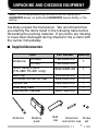
UNPACKING AND CHECKING EQUIPMENT
Note: The following unpacking instructions are for use by your
KENWOOD dealer, an authorized KENWOOD service facility, or the
factory.
Carefully unpack the transceiver. We recommend that
you identify the items listed in the following table before
discarding the packing material. If any items are missing
or have been damaged during shipment, file a claim with
the carrier immediately.
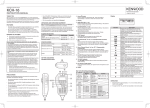
■ Supplied Accessories
Item
TK-480
Antenna
TK-481
NiCd battery pack
(TK-480/ TK-481 only)
Belt clip
Univeral connector cap
Screw set
Warranty card
Instruction manual
Antenna
Battery
pack
Part Number Quantity
T90-0636-XX
1
T90-0640-XX
W09-0900-XX
1
J29-0658-XX
B09-0363-XX
N99-2004-XX
––
B62-1483-XX
1
1
1
1
1
Belt
clip
Universal
Screw
connector cap set
1
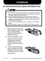
PREPARATION
■ Installing/ Removing the (Optional) NiCd Battery Pack
◆ Do not recharge the battery pack if it is already fully charged.
Doing so may cause the life of the battery pack to shorten or
the battery pack may be damaged.
◆ After recharging the battery pack, disconnect it from the
charger. If the charger power is reset (turned on after being
turned off), recharging will start again and the battery pack
will become overcharged.
◆ Do not short the battery terminals or dispose of the battery
by fire.
◆ Never attempt to remove the casing from the battery pack.
1 Match the four grooves
of the battery pack with
the corresponding
guides on the back of
the transceiver.
2 Slide the battery pack
along the back of the
transceiver until the
release latch on the
base of the transceiver
locks.
3 To remove the battery
pack, pull back on the
release latch and slide
the pack away from the
transceiver.
2
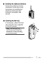
■ Installing the (Optional) Antenna
Screw the antenna into the
connector on the top of the
transceiver by holding the
antenna at its base and
turning it clockwise until
secure.
■ Installing the Belt Clip
If necessary, attach the belt
clip using the two supplied
3 x 6 mm screws.
Note: If the belt clip is not
installed, its mounting location
may get hot during continuous
transmission or when left sitting
in a hot environment.
3
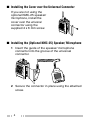
■ Installing the Cover over the Universal Connector
If you are not using the
optional KMC-25 speaker/
microphone, install the
cover over the univeral
connector using the
supplied 4 x 6 mm screw.
■ Installing the (Optional KMC-25) Speaker/ Microphone
1 Insert the guide of the speaker/ microphone
connector into the groove of the universal
connector.
2 Secure the connector in place using the attached
screw.
4
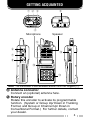
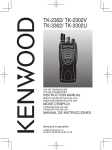
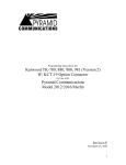
GETTING ACQUAINTED
q w e
t
r
Microphone
Speaker
o
y
!2
u
i
!0
!1
Note: The transceiver is also available without the DTMF keypad (!1).
q Antenna connector
Connect an (optional) antenna here.
w Rotary encoder
Rotate this encoder to activate its programmable
function. (System or Group Up/ Down in Trunking
Format, and Group or Channel Up/ Down in
Conventional Format.) For further details, contact
your dealer.
5
e POWER switch/ VOLUME control
Turn clockwise to switch ON the transceiver. Rotate
to adjust the volume. Turn counterclockwise fully to
switch OFF the transceiver.
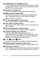
r Auxiliary (orange) key
Press to activate its auxiliary function {page 8}.
t Battery pack release latch
Pull back on this latch to release the battery pack.
See “Installing/ Removing the (Optional) NiCd
Battery Pack” on page 2.
y PF (Programmable Function) key
Press to activate its auxiliary function {page 8}.
u PTT (Push-To-Talk) switch
Press this switch, then speak into the microphone to
call a station.
i PF (Programmable Function) key
Press to activate its auxiliary function {page 8}.
o Transmit/ Battery low indicator
This red LED lights during transmission. If
programmed by your dealer, when the battery pack
power is low, the LED flashes during transmission.
Replace or recharge the battery pack.
!0 S, A, tB, and Cs
s keys
Press to activate their auxiliary functions {page 8}.
!1 DTMF keypad (keypad models only)
Press the keys on the keypad to send DTMF tones.
!2 Universal connector
Connect the (optional KMC-25) speaker/ microphone
here. Otherwise, keep the supplied cover in place.
6
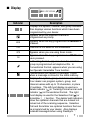
■ Display
MON SVC SCN LO
Indicator
Description
MON
Displays the system, channel, and group numbers.
Also displays various functions which have been
programmed by your dealer.
Appears when the selected channel is
programmed as priority.
Appears when the key programmed as Monitor is
pressed.
SVC
This icon is not used on this transceiver.
SCN
LO
Appears when you are using Scan mode.
Appears when the key programmed as RF Power
Lo is pressed.
In Trunking Format, appears when the selected
group is programmed as telephone IDs. In
Conventional Format, appears when you are using
the Operator Selectable Tone function.
Flashes when you receive a message. Lights
when a message is stored in the stack memory.
Displays the system, group, and channel numbers.
Your dealer can program system, group, and
channel names with up to 10 characters, in place
of numbers. The left most display is used as a
delete indicator ( ) in Trunking Format and an add
indicator ( ) in Conventional Format. The right
most display is used for the Selective Call ( ) or
Scrambler ( _ ) function. The delete/ add indicators
show the systems/ channels that are locked/ not
locked out of the scanning sequence. Selective
Call and Scrambler are optional functions that can
be programmed by your dealer. Also displays
received messages when using FleetSync .
7
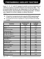
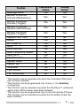
PROGRAMMABLE AUXILIARY FUNCTIONS
Keys r, y, i, and !0 {pages 5 and 6} can be programmed
with the auxiliary functions listed in the following table. The
programmable functions are dependant on the operation of
the transceiver (Conventional or Trunking Format). Contact
your dealer for further details on these functions.
Note:
◆ If “Function” is programmed onto a key, the DTMF keypad (keypad
models only) can also be used for additional programmable keys.
◆ Conventional Format is available for only the TK-280 and TK-380
models.
Function
Auto Tel
AUX 1
Channel Down
Channel Up
DTMF ID (BOT)
DTMF ID (EOT)
Display Character
Emergency 2
Function
Group Down
Group Up
Home Channel
Home Group
Key Lock
Lamp
Memory (RCL/STO)
Memory (RCL)
Memory (STO)
8
Conventional
Format
No
Yes
Yes
Yes
Yes
Yes
Yes
Yes
Yes
Yes
Yes
Yes
No
Yes
Yes
Yes
Yes
Yes
Trunking
Format
Yes
Yes
No
No
Yes
Yes
Yes
Yes
Yes
Yes
Yes
No
Yes
Yes
Yes
Yes
Yes
Yes
Function
Message Mode
Monitor A (Monitor
Unmute (Momentary))
Monitor B (Monitor
Unmute (Toggle))
Monitor C (Carrier
Squelch (Momentary))
Monitor D (Carrier
Squelch (Toggle))
Operator Sel Tone
Redial
RF Power Lo
Scan
Scan Del/Add
Scan Temporary Delete
Send GPS 3
SP Attenuation 4
System Down
System Up
Scrambler 5
Talk Around
TEL Disconnect
1
2
3
4
5
Conventional
Format
Yes
Trunking
Format
Yes
Yes
Yes
Yes
Yes
Yes
Yes
Yes
Yes
Yes
Yes
Yes
Yes
Yes
No
Yes
Yes
No
No
Yes
Yes
No
No
Yes
Yes
Yes
Yes
Yes
Yes
Yes
Yes
Yes
Yes
No
Yes
This function can be selected only when the Scrambler/ ANI board
has not been installed.
This function can be programmed only on key r, the Auxiliary
(orange) key.
This function can be selected only when the FleetSync™ enhanced
option and a GPS receiver have been installed.
This function can be programmed only on the microphone PF keys.
This function can be selected only when the Scrambler board has
been installed.
9
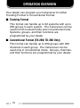
OPERATION OVERVIEW
Your dealer can program your transceiver for either
Trunking Format or Conventional Format.
■ Trunking Format
This format can handle up to 32 systems with up to
250 groups in each system. The transceiver can be
used in both trunked mode and conventional mode.
Systems, groups, and their functions are
programmed by your dealer.
■ Conventional Format (TK-280/ TK-380 Only)
This format can handle up to 250 groups with 250
channels in each group. The transceiver can be
used only in conventional mode. Groups, channels,
and their functions are programmed by your dealer.
10
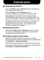
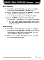
OPERATING BASICS
■ Switching Power ON/ OFF
Turn the Power switch/ Volume control clockwise to
switch the transceiver ON.
Turn the Power switch/ Volume control
counterclockwise to switch the transceiver OFF.
If the Radio Password function is programmed,
“PASSWORD” will appear on the display when the
power is turned ON. To unlock the transceiver, enter
the password, then press the S key. If you enter the
wrong password, an error tone sounds and the
transceiver remains locked. The password can
contain a maximum of 6 digits.
■ Adjusting the Volume
Rotate the Power switch/ Volume control to adjust
the volume. Clockwise increases the volume and
counterclockwise decreases it.
■ Selecting a System/ Group/ Channel
Select the desired system and group (Trunking
Format) using the encoder and the keys programmed
with System or Group Up/ Down.
Select the desired group and channel (Conventional
Format) using the encoder and the keys programmed
with Group or Channel Up/ Down.
11
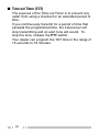
■ Time-out Timer (TOT)
The purpose of the Time-out Timer is to prevent any
caller from using a channel for an extended period of
time.
If you continuously transmit for a period of time that
exceeds the programmed time, the transceiver will
stop transmitting and an alert tone will sound. To
stop the tone, release the PTT switch.
Your dealer can program the TOT time in the range of
15 seconds to 10 minutes.
12
TRUNKED OPERATION (Trunking Format)
■ Placing a Dispatch Call
1 Select the desired system and group using the
encoder and the System or Group keys.
2 Press the PTT switch.
3 If a tone does not sound, communication is
possible; start speaking into the microphone.
Release the PTT switch to receive.
•
For best sound quality at the receiving station, hold
the microphone approximately 1.5 inches (3 ~ 4 cm)
from your mouth.
■ Receiving a Dispatch Call
1 Select the desired system and group using the
encoder and the System or Group keys. (If the
Scan function has been programmed, you can
switch it ON or OFF as desired.)
2 When you hear the dispatcher’s voice, readjust
the volume as necessary.
13
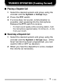
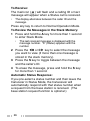
■ Placing a Telephone Call (Keypad Models Only)
1 Select the desired system and group using the
encoder and the System or Group keys.
2 Press and hold the PTT switch for approximately
1 second to ensure a connection.
•
Confirm that there is a dial tone after you release the
PTT switch.
3 Press and hold the PTT switch, then dial using
the front panel keypad.
•
After dialing, release the PTT switch and wait for a
response from the called party.
4 When the called party responds, press the PTT
switch and speak into the microphone. Release
the PTT switch to receive.
•
Only one person can speak at a time.
5 To end the call, press and hold the PTT switch,
then press the # key or the key programmed as
Tel Disconnect.
■ Receiving a Telephone Call (Keypad Models Only)
1 Select the desired system and group using the
encoder and the System or Group keys. (If the
Scan function has been programmed, you can
switch it ON or OFF as desired.)
•
A ringing tone will sound when a call is received.
2 Press and hold the PTT switch to speak, and
release it to receive.
•
Only one person can speak at a time.
3 To end the call, press and hold the PTT switch,
then press the # key or the key programmed as
Tel Disconnect.
14
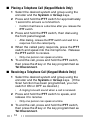
CONVENTIONAL OPERATION (Trunking Format)
■ Transmitting
1 Select the desired system and group using the
encoder and the System or Group keys.
2 Press the key programmed as Monitor to check
whether or not the channel is free.
•
If the channel is busy, wait until it becomes free.
3 Press the PTT switch and speak into the
microphone. Release the PTT switch to receive.
•
For best sound quality at the receiving station, hold
the microphone approximately 1.5 inches (3 ~ 4 cm)
from your mouth.
■ Receiving
1 Select the desired system and group using the
encoder and the System or Group keys. (If the
Scan function has been programmed, you can
switch it ON or OFF as desired.)
2 When you hear the dispatcher’s voice, readjust
the volume as necessary.
15
SYSTEM SCAN (Trunking Format)
If the Scan function is programmed, systems can be
scanned by pressing the key programmed as Scan.
When the Scan key is pressed, the SCN indicator and
“-SCAN-” or the revert system/ group number, appear on
the display and scanning starts. The systems not locked
out of the scanning sequence are scanned.
When a call is received, scanning stops and the system
and group digits appear. Press the PTT switch and
speak into the microphone to respond to the call. The
transceiver will continue scanning after a predetermined
time delay if the PTT switch is released and no further
signal is received.
■ Scanning Trunked Systems
When scanning trunked systems, the revert groups
and the groups not locked out of the scanning
sequence are scanned. See “GROUP SCAN” on
page 18.
■ Scanning Conventional Systems
When scanning conventional systems, the revert
groups and the groups not locked out of the scanning
sequence are scanned. See “GROUP SCAN” on
page 18.
16
■ Scan Lockout
If a programmable auxiliary key is programmed with
Scan Del/Add, each system can be locked out of the
scan sequence manually. The delete indicator ( s )
will appear on the display when the selected system
is locked out.
■ Scan Revert
You can select revert systems and groups using the
encoder and the System or Group keys.
Four types of Scan Reverts which can be
programmed by your dealer are available:
• Last Called Revert: The last system/ group
received is assigned as the new revert system
and group.
• Last Used Revert: The last system/ group
responded to is assigned as the new revert
system and group.
• Selected: The last system/ group selected is
assigned as the new revert system and group.
• Selected + Talkback: If the system/ group has
been changed during Scan, the newly selected
system/ group is assigned as the new revert
system and group. The transceiver “talks back”
on the current receive group.
17
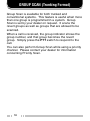
GROUP SCAN (Trunking Format)
Group Scan is available for both trunked and
conventional systems. This feature is useful when more
than one group is programmed in a system. Group
Scan is set by your dealer on request. It scans the
revert groups as well as groups that are allowed to be
scanned.
When a call is received, the group indicator shows the
group number, and that group becomes the revert
group. Simply press the PTT switch to respond to the
call.
You can also perform Group Scan while using a priority
channel. Please contact your dealer for information
concerning Priority Scan.
18
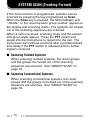
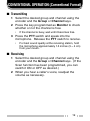
CONVENTIONAL OPERATION (Conventional Format)
■ Transmitting
1 Select the desired group and channel using the
encoder and the Group or Channel keys.
2 Press the key programmed as Monitor to check
whether or not the channel is free.
•
If the channel is busy, wait until it becomes free.
3 Press the PTT switch and speak into the
microphone. Release the PTT switch to receive.
•
For best sound quality at the receiving station, hold
the microphone approximately 1.5 inches (3 ~ 4 cm)
from your mouth.
■ Receiving
1 Select the desired group and channel using the
encoder and the Group or Channel keys. (If the
Scan function has been programmed, you can
switch it ON or OFF as desired.)
2 When you hear a caller’s voice, readjust the
volume as necessary.
19
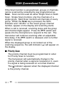
SCAN (Conventional Format)
If the Scan function is programmed, groups or channels
can be scanned by pressing the key programmed as
Scan. Scan can be used as either Single Scan or Multi
Scan. Single Scan monitors only the channels of a
single group. Multi Scan monitors all channels of every
group. When the Scan key is pressed, the SCN
indicator and “-SCAN-” or the revert group/ channel
number, appear on the display and scanning starts.
When a call is received, scanning stops and the group
and channel digits appear. Press the PTT switch and
speak into the microphone to respond to the call. The
transceiver will continue scanning after an adjustable
time delay, if the PTT switch is released, and no further
signal is received.
When the displayed group is not locked out of the
scanning sequence, the add indicator ( ) will appear on
the display.
■ Priority Scan
The priority channel must be programmed in order
for Priority Scan to function.
The transceiver will automatically change to the
priority channel when a signal is received on it, even
if a signal is being received on a normal channel.
The indicator appears when the displayed channel
is the priority channel.
20
2-TONE SIGNALLING (Conventional Format)
2-Tone Signalling is either activated or deactivated by
your dealer.
2-Tone Signalling only opens the squelch when the
transceiver receives two tones corresponding to those
set up in the transceiver. When the squelch opens, you
will be able to hear the caller without any further action.
After a correct 2-Tone signal is received and the squelch
opens, pressing the key programmed as Monitor will
cancel the connection.
If your dealer programmed Transpond for 2-Tone
Signalling, your transceiver will automatically send an
acknowledgment signal to the station that called you
with the correct 2-Tone signal. Transpond does not
function when you are called as a Group call.
If your dealer programmed Tone Alert for 2-Tone
Signalling, your transceiver will emit a beep when the
correct 2-Tone signal is received.
Note: This transceiver is only capable of decoding 2-Tone Signals. It
cannot encode a 2-Tone Signal.
21
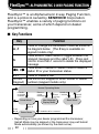
FleetSync™: ALPHANUMERIC 2-WAY PAGING FUNCTION
FleetSync™ is an Alphanumeric 2-way Paging Function,
and is a protocol owned by KENWOOD Corporation.
FleetSync™ enables a variety of paging functions on
your transceiver, some of which depend on dealer
programming.
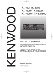
■ Key Functions
Key
Function
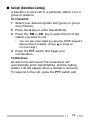
Press to change the transceiver mode as shown in
the diagram below. (The # key is available on
keypad models only).
Press while in Stack Mode to toggle between the
received message and the caller’s ID. Press and
S
hold for more than 1 second to delete the displayed
message.
Press while in Selcall or Status mode to select a
tB, Cs
s
station ID or your transceiver status.
PTT
Press to initiate a call.
(DTMF
Use the DTMF keypad to enter Selcall or Status
Keypad) numbers (keypad models only).
A, #
Normal Operating Mode
Press A
or receive
a Selcall
Receive
a new
message
Selcall Mode
1
Hold A for
Press 1 second
any key
New Message
Display Mode
Press
A or #
Stack Mode
Press
A or #
Press
A or #
1
Status Mode
Hold A or # for 1 second
Depending on how your dealer programmed the transceiver,
Selcall Mode may be skipped or the transceiver may exit Selcall
Mode automatically (as shown by the dash arrow).
22
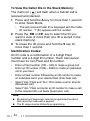
■ Selcall (Selective Calling)
A Selcall is a voice call to a particular station or to a
group of stations.
To Transmit:
1 Select your desired system and group (or group
and channel).
2 Press the A key to enter Selcall Mode.
3 Press the tB or Cs key to select the ID of the
station you want to call.
•
You can also enter digits by using the DTMF keypad if
Manual Dial is enabled. (Press to erase an
incorrect digit.)
4 Press the PTT switch and begin your
conversation.
To Receive:
An alert tone will sound, the transceiver will
automatically enter Selcall Mode, and the calling
station’s ID will appear when a Selcall is received.
To respond to the call, press the PTT switch and
23
To View the Caller IDs in the Stack Memory:
The mail icon ( ) will flash when a Selcall call is
received and stacked.
1 Press and hold the A key for more than 1 second
to enter Stack Mode.
•
The last received Caller ID is displayed with the Caller
ID number. “I” (ID) appears with the number.
2 Press the tB or Cs key to select the ID you
want to view (if more than one ID is stored in the
stack memory).
3 To erase the ID, press and hold the S key for
more than 1 second.
Identification Codes:
An ID code is a combination of a 3-digit Fleet
number and a 4-digit ID number. Each transceiver
must have its own Fleet and ID number.
•
•
•
•
•
Enter a Fleet number (100 ~ 349) to make a group call.
Enter an ID number (1000 ~ 4999) to make an individual
call in your fleet.
Enter a Fleet number followed by an ID number to make
an individual call in your desired fleet (Inter-fleet call).
Select “ALL” Fleet and “ALL” ID to make a call to all units
(Broadcast call).
Select “ALL” Fleet and enter an ID number to make a call
to the selected ID in all fleets (Supervisor call).
Note:
◆ Broadcast and Supervisor calls are programmed functions
that cannot be made with a keypad.
◆ The ID range may be limited by programming.
24
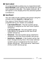
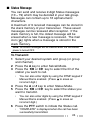
■ Status Message
You can send and receive 2-digit Status messages
(10 ~ 79) which may be decided in your talk group.
Messages can contain up to 16 alphanumeric
characters.
A maximum of 9 received messages can be stored in
the stack memory of your transceiver. These saved
messages can be reviewed after reception. If the
stack memory is full, the oldest message will be
erased when a new message is received. The mail
icon ( ) lights when a message is stored in the
stack memory.
Note: All stored messages will be cleared when the transceiver
power is turned OFF.
To Transmit:
1 Select your desired system and group (or group
and channel).
2 Press the A key to enter Selcall Mode.
3 Press the tB or Cs key to select the ID of the
station you want to call.
•
You can also enter digits by using the DTMF keypad if
Manual Dial is enabled. (Press to erase an
incorrect digit.)
4 Press the A or # key to enter Status Mode.
5 Press the tB or Cs key to select the status you
want to transmit.
•
You can also enter digits by using the DTMF keypad if
Manual Dial is enabled. (Press to erase an
incorrect digit.)
6 Press the PTT switch to initiate the Status call.
•
“COMPLETE” is displayed when the call has been
successfully transmitted.
25
To Receive:
The mail icon ( ) will flash and a calling ID or text
message will appear when a Status call is received.
•
The display alternates between the caller ID and the
message.
Press any key to return to Normal Operation Mode.
To Review the Messages in the Stack Memory:
1 Press and hold the A key for more than 1 second
to enter Stack Mode.
•
The last received message is displayed with the
message number. “S” (Status) appears with the
number.
2 Press the tB or Cs key to select the message
you want to view (if more than one message is
stored in the stack memory).
3 Press the S key to toggle between the message
and the caller’s ID.
4 To erase the message, press and hold the S key
for more than 1 second.
Automatic Status Response:
If you pre-select a status number and then leave the
transceier in Status Mode, the transceiver will
automatically respond with that status number when
a request from the base station is received. (The
base station request function is optional.)
26
■ Optional Short Messages Feature
Received short messages (maximum of 48
characters) are displayed the same as Status
messages {page 24}, however only 4 short
messages can be stored in the stack memory. “M”
(Message) and the message number appear with the
message.
27
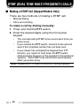
DTMF (DUAL TONE MULTI FREQUENCY) CALLS
■ Making a DTMF Call (Keypad Models Only)
There are two methods of making a DTMF call:
•
•
Manual dialing
Store and sending
To make a call by dialing manually:
1 Press and hold the PTT switch.
2 Enter the desired digits using the front panel
keypad.
•
•
•
The corresponding DTMF tones sound each time you
press a key.
If you release the PTT switch, transmit mode will end
even if the complete number has not been sent.
If your dealer has activated the Keypad Auto PTT
function, you need not hold down the PTT switch
while pressing the keys on the keypad in Conventional
systems. The DTMF code will be sent automatically
when you press a key.
Note: Keypad Auto PTT does not function in Trunking systems.
28
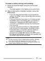
To make a call by storing and sending:
1 Enter the desired digits using the front panel
keypad.
•
The digits appear on the display as you enter them.
2 After entering the complete number, press the
PTT switch.
•
•
•
If you are using the transceiver in a Conventional
system, the DTMF code is transmitted after pressing
the PTT switch.
If you are using the transceiver in a Trunking system,
the DTMF code is transmitted after a connection is
established. Releasing the PTT switch before a
connection is established will stop the transmission
from occuring.
If you are using the transceiver in a RIC (Repeater
Inter-Connect) Trunking system, the DTMF code is
transmitted after a connection with the telephone
system is established. If you press the key
programmed as Auto Tel instead of the PTT switch,
the call will automatically connect to the repeater, and
the DTMF code will be transmitted.
Note:
◆ You can only store up to 16 digits before sending. Entering
more than 16 digits will cause an error tone to sound.
◆ If you switch the power OFF before sending the number, the
number will be cleared from memory.
29
■ DTMF Signalling
Your dealer can program a group with a DTMF
signalling code. When you receive a call with a code
that matches yours, the signalling indicator will flash
and a tone will sound. Squelch opens and you will
hear the call.
Squelch will close when you receive a call with a
code that matches your signalling reset code.
When making a call on a group programmed with a
DTMF signalling code, the signalling indicator will
light and the squelch will open.
■ DBD (Dead Beat Disable)
Depending on how your dealer programs your
transceiver, when you receive a call containing a
DBD code, either transmit mode or receive and
transmit modes will be disabled. When a DBD code
is received, a tone will sound.
DBD is cancelled when you receive a call with a DBD
cancel code.
30
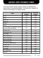
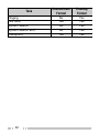
AUDIBLE USER FEEDBACK TONES
The transceiver emits various tones to indicate the
transceiver’s operating status. Contact your dealer for
further information on these tones.
Tone
Alert
Busy
DBD On
DBD Off
Delay
Deny
Free System Ring Back Mode/
System Search Mode
Group Call
Individual Call
Intercept
Key Input Error
Key Press [A]
Key Press [B]
Key Press [C]
Password Agreement
Power ON
Pre Alert
Proceed
PTT Release
Queue
Conventional
Format
Trunking
Format
Yes
Yes
Yes
Yes
No
No
Yes
Yes
Yes
Yes
Yes
Yes
No
Yes
Yes
Yes
No
Yes
Yes
Yes
Yes
Yes
Yes
Yes
No
Yes
No
Yes
Yes
Yes
Yes
Yes
Yes
Yes
Yes
Yes
No
Yes
Yes
Yes
31
Tone
Ringing
Roll Over
System Search
System Search End
Transpond
32
Conventional
Format
Trunking
Format
No
Yes
No
No
Yes
Yes
Yes
Yes
Yes
Yes