1
INSTRUCTION MANUAL
VHF FM TRANSCEIVER
TK-2140
TK-3140
UHF FM TRANSCEIVER
KENWOOD CORPORATION
© B62-1476-00 (K)
09 08 07 06 05 04 03 02 01 00
THANK YOU
We are grateful you chose KENWOOD for your land
mobile radio applications. We believe this easy-to-use
transceiver will provide dependable communications to
keep personnel operating at peak efficiency.
KENWOOD transceivers incorporate the latest in
advanced technology. As a result, we feel strongly that
you will be pleased with the quality and features of this
product.
MODELS COVERED BY THIS MANUAL
• TK-2140: VHF FM Transceiver
• TK-3140: UHF FM Transceiver
NOTICES TO THE USER
◆ Government law prohibits the operation of unlicensed radio
transmitters within the territories under government control.
◆ Illegal operation is punishable by fine and/or imprisonment
◆ Refer service to qualified technicians only.
SAFETY: It is important that the operator is aware of
and understands hazards common to the operation of
any transceiver.
WARNING:
EXPLOSIVE ATMOSPHERES (GASES, DUST, FUMES, etc.)
Turn off your transceiver while taking on fuel, or while parked in
gasoline service stations.
i
One or more of the following statements may be
applicable:
FCC WARNING
This equipment generates or uses radio frequency energy. Changes
or modifications to this equipment may cause harmful interference
unless the modifications are expressly approved in the instruction
manual. The user could lose the authority to operate this equipment
if an unauthorized change or modification is made.
INFORMATION TO THE DIGITAL DEVICE USER REQUIRED BY
THE FCC
This equipment has been tested and found to comply with the limits
for a Class B digital device, pursuant to Part 15 of the FCC Rules.
These limits are designed to provide reasonable protection against
harmful interference in a residential installation.
This equipment generates, uses and can generate radio frequency
energy and, if not installed and used in accordance with the
instructions, may cause harmful interference to radio communications.
However, there is no guarantee that the interference will not occur in a
particular installation. If this equipment does cause harmful
interference to radio or television reception, which can be determined
by turning the equipment off and on, the user is encouraged to try to
correct the interference by one or more of the following measures:
• Reorient or relocate the receiving antenna.
• Increase the separation between the equipment and receiver.
• Connect the equipment to an outlet on a circuit different from that
to which the receiver is connected.
• Consult the dealer for technical assistance.
ATTENTION (U.S.A. Only):
The RBRC Recycle seal found on KENWOOD
nickel-cadmium (Ni-Cd) battery packs indicates
KENWOOD’s voluntary participation in an industry
program to collect and recycle Ni-Cd batteries after
their operating life has expired. The RBRC program
is an alternative to disposing Ni-Cd batteries with
your regular refuse or in municipal waste streams,
which is illegal in some areas.
For information on Ni-Cd battery recycling in your area, call (toll free)
1-800-8-BATTERY (1-800-822-8837).
KENWOOD’s involvement in this program is part of our commitment
to preserve our environment and conserve our natural resources.
ii
CONTENTS
UNPACKING AND CHECKING EQUIPMENT ................... 1
SUPPLIED ACCESSORIES ......................................... 1
PREPARATION .................................................. 2
BATTERY PACK PRECAUTIONS .................................... 2
INSTALLING/ REMOVING THE (OPTIONAL) RECHARGEABLE BATTERY
PACK OR ALKALINE BATTERY CASE ............................... 6
INSTALLING/ REMOVING ALKALINE BATTERIES ...................... 7
INSTALLING THE (OPTIONAL) ANTENNA ............................ 8
INSTALLING THE BELT CLIP ....................................... 8
INSTALLING THE COVER OVER THE UNIVERSAL CONNECTOR .......... 9
INSTALLING THE (OPTIONAL KMC-25) SPEAKER/ MICROPHONE .... 9
GETTING ACQUAINTED .......................................10
DISPLAY ......................................................12
PROGRAMMABLE AUXILIARY FUNCTIONS ................ 13
OPERATION OVERVIEW.......................................15
TRUNKING FORMAT ............................................15
CONVENTIONAL FORMAT ........................................15
OPERATING BASICS ...........................................16
SWITCHING POWER ON/ OFF .................................. 16
ADJUSTING THE VOLUME .......................................16
SELECTING A SYSTEM/ GROUP/ CHANNEL ........................16
TIME-OUT TIMER (TOT) .......................................17
TRUNKED OPERATION (Trunking Format) .................. 18
PLACING A DISPATCH CALL .....................................18
RECEIVING A DISPATCH CALL ...................................18
iii
CONVENTIONAL OPERATION (Trunking Format) ...........19
TRANSMITTING .................................................19
RECEIVING ....................................................19
SYSTEM SCAN (Trunking Format) ...........................20
SCANNING TRUNKED SYSTEMS ..................................20
SCANNING CONVENTIONAL SYSTEMS .............................20
SCAN LOCKOUT ................................................21
SCAN REVERT .................................................21
GROUP SCAN (Trunking Format) ............................22
CONVENTIONAL OPERATION (Conventional Format) .....23
TRANSMITTING .................................................23
RECEIVING ....................................................23
SCAN (Conventional Format) ................................24
PRIORITY SCAN ................................................24
2-TONE SIGNALLING (Conventional Format) .............. 25
FleetSync™: ALPHANUMERIC 2-WAY PAGING FUNCTION ... 26
KEY FUNCTIONS ...............................................26
SELCALL (SELECTIVE CALLING) .................................27
STATUS MESSAGE .............................................29
OPTIONAL SHORT MESSAGES FEATURE ..........................31
AUDIBLE USER FEEDBACK TONES ..........................32
iv
UNPACKING AND CHECKING EQUIPMENT
Note: The following unpacking instructions are for use by your
KENWOOD dealer, an authorized KENWOOD service facility, or the
factory.
Carefully unpack the transceiver. We recommend that
you identify the items listed in the following table before
discarding the packing material. If any items are missing
or have been damaged during shipment, file a claim with
the carrier immediately.
SUPPLIED ACCESSORIES
Item
Part Number
Quantity
Belt clip
J29-0688-XX
1
Univeral connector cap
B09-0625-XX
1
Dressed screw
N08-0548-XX
1
Warranty card
—
1
B62-1476-XX
1
Instruction manual
Belt clip
Universal
connector cap
Dressed
screw
1
PREPARATION
BATTERY PACK PRECAUTIONS
◆ Do not recharge the battery pack if it is already fully charged.
Doing so may cause the life of the battery pack to shorten or the
battery pack may be damaged.
◆ After recharging the battery pack, disconnect it from the charger.
If the charger power is reset (turned ON after being turned OFF),
recharging will start again and the battery pack will become
overcharged.
◆ Do not use the transceiver while charging the battery pack. We
recommend you switch the transceiver power OFF while charging
is taking place.
◆ Do not short the battery terminals or dispose of the battery by
fire.
◆ Never attempt to remove the casing from the battery pack.
Information concerning the (optional) Li-ion battery pack:
The battery pack includes flammable objects such as organic solvent.
Mishandling may cause the battery to rupture producing flames or
extreme heat, deteriorate, or cause other forms of damage to the
battery. Please observe the following prohibitive matters.
DANGER
•
•
Do not disassemble or reconstruct battery!
The battery pack has a safety function and protection circuit to
avoid danger. If they suffer serious damage, the battery may
generate heat or smoke, rupture, or burst into flame.
Do not short-circuit the battery!
Do not join the + and – terminals using any form of metal (such as
a paperclip or wire). Do not carry or store the battery pack in
containers holding metal objects (such as wires, chain-neckless or
hairpins). If the battery pack is short-circuited, excessive current
will flow and the battery may generate heat or smoke, rupture, or
burst into flame. It will also cause metal objects to heat up.
2
•
•
•
•
•
•
•
Do not incinerate or apply heat to the battery!
If the insulator is melted, the gas release vent or safety function is
damaged, or the electrolyte is ignited, the battery may generate
heat or smoke, rupture, or burst into flame.
Do not use or leave the battery near fires, stoves, or other
heat generators (areas reaching over 80°C)!
If the polymer separator is melted due to high temperature, an
internal short-circuit may occur in the individual cells and the
battery may generate heat or smoke, rupture, or burst into flame.
Do not immerse the battery in water or get it wet by other
means!
If the battery’s protection circuit is damaged, the battery may
charge at extreme current (or voltage) and an abnormal chemical
reaction may occur. The battery may generate heat or smoke,
rupture, or burst into flame.
Do not charge the battery near fires or under direct sunlight!
If the battery’s protection circuit is damaged, the battery may
charge at extreme current (or voltage) and an abnormal chemical
reaction may occur. The battery may generate heat or smoke,
rupture, or burst into flame.
Use only the specified charger and observe charging
requirements!
If the battery is charged in unspecified conditions (under high
temperature over the regulated value, excessive high voltage or
current over regulated value, or with a remodelled charger), it
may overcharge or an abnormal chemical reaction may occur.
The battery may generate heat or smoke, rupture, or burst into
flame.
Do not pierce the battery with any object, strike it with an
instrument, or step on it!
This may break or deform the battery, causing a short-circuited.
The battery may generate heat or smoke, rupture, or burst into
flame.
Do not jar or throw the battery!
An impact may cause the battery to leak, generate heat or smoke,
rupture, and/or burst into flame. If the battery’s protection circuit is
damaged, the battery may charge at an abnormal current (or
voltage), and an abnormal chemical reaction may occur. The
battery may generate heat or smoke, rupture, or burst into flame.
3
•
•
•
•
•
•
•
Do not use the battery pack if it is damaged in any way!
The battery may generate heat or smoke, rupture, or burst into
flame.
Do not solder directly onto the battery!
If the insulator is melted or the gas release vent or safety function
is damaged, the battery may generate heat or smoke, rupture, or
burst into flame.
Do not reverse the battery polarity (and terminals)!
When charging a reversed battery, an abnormal chemical
reaction may occur. In some cases, an unexpected large amount
of current may flow upon discharging. The battery may generate
heat or smoke, rupture, or burst into flame.
Do not reverse-charge or reverse-connect the battery!
The battery pack has positive and negative poles. If the battery
pack does not smoothly connect with a charger or operating
equipment, do not force it; check the polarity of the battery. If the
battery pack is reverse-connected to the charger, it will be
reverse-charged and an abnormal chemical reaction may occur.
The battery may generate heat or smoke, rupture, or burst into
flame.
Do not touch a ruptured and leaking battery!
If the electrolyte liquid from the battery gets into your eyes, wash
your eyes out with fresh water as soon as possible, without
rubbing your eyes. Go to the hospital immediately. If left
untreated, it may cause eye-problems.
Do not charge the battery for longer than the specified time!
If the battery pack has not finished charging even after the
regulated time has passed, stop it. The battery may generate
heat or smoke, rupture, or burst into flame.
Do not place the battery pack into a microwave or high
pressure container!
The battery may generate heat or smoke, rupture, or burst into
flame.
4
•
Keep ruptured and leaking battery packs away from fire!
If the battery pack is leaking (or the battery emits a bad odor),
immediately remove it from flammable areas. Electrolyte leaking
from battery can easily catch on fire and may cause the battery to
generate smoke or burst into flame.
Do not use an abnormal battery!
If the battery pack emits a bad odor, appears to have different
coloring, is deformed, or seems abnormal for any other reason,
remove it from the charger or operating equipment and do not
use it. The battery may generate heat or smoke, rupture, or burst
into flame.
•
■ Using the Li-ion Battery Pack
•
•
•
Charge the battery pack before using it.
To keep the battery discharge at a minimum, remove the battery
pack from the equipment when it is not in use. Store the battery
pack in a cool and dry location.
When storing the battery pack for a long period:
1 Remove the battery pack from the equipment.
2 Discharge the battery pack, if possible.
3 Store the battery pack in a cool (below 25°C) and dry
location.
■ Characteristics of the Li-ion Battery Pack
•
•
•
•
•
As the battery pack is charged and discharged repeatedly, the
battery capacity decreases.
Even if the battery pack is unused, the battery pack degrades.
It takes a longer time to charge the battery pack in cooler areas.
The life of battery pack is shortened when it is charged and
discharged in hotter areas. When the battery pack is stored in a
hot location, the battery pack degrades quicker. Do not leave
the battery pack in vehicles or near heating appliances.
When the battery pack operating time becomes short, even if it
is fully charged, replace the battery pack. Continuing to charge
and discharge the battery pack may result in elecrolyte leakage.
5
INSTALLING/ REMOVING THE (OPTIONAL) RECHARGEABLE BATTERY
PACK OR ALKALINE BATTERY CASE
1 Match the guides of the
battery pack with the
corresponding grooves on
the upper rear of the
transceiver, then firmly press
the battery pack to lock it in
place.
2 Flip the safety catch into
place to prevent accidentally
pressing the release latch
and removing the battery.
3 To remove the battery pack,
lift the safety catch, press the
release latch, then pull the
battery pack away from the
transceiver.
Note: When lifting the safety catch,
make sure you do not lift both the
catch and the release latch at the
same time as you may inadvertantly
damage the release latch. This is
especially true when using an
implement such as a small screw
driver to lift the safety catch.
6
INSTALLING/ REMOVING ALKALINE BATTERIES
◆ Do not install batteries in a hazardous environment where sparks
could cause an explosion.
◆ Never discard old batteries in fire; extremely high temperatures can
cause batteries to explode.
◆ Do not short circuit the battery case terminals.
◆ Do not use commercially available rechargeable batteries.
Note:
◆ If you do not plan to use the transceiver for a long period, remove
the batteries from the battery case.
◆ This battery case has been designed for transmitting at a power
of approximately 1 W (the low power setting on your transceiver).
If you want to transmit a stronger signal (using the high power
setting on your transceiver), use an optional rechargeable battery
pack.
1 To open the battery case,
press on the two tabs on the
upper rear of the case then
pull the two halves apart.
2 Insert 6 AA (LR 6) alkaline
batteries into the battery
case.
•
Be sure to match the
polarities with those marked
in the bottom of the battery
case.
3 Align the tabs of the cover
with the base, then push
down on the cover until it
locks in place.
7
INSTALLING THE (OPTIONAL) ANTENNA
Screw the antenna into the
connector on the top of the
transceiver by holding the
antenna at its base and turning
it clockwise until secure.
INSTALLING THE BELT CLIP
Note: When first installing the belt
clip, you must remove the battery
pack from the rear of the transceiver.
1 Remove the two screws
from the rear of the
transceiver, then remove the
small, plastic black covering
that was held in place.
2 Insert the belt clip mount
into the space on the rear of
the transceiver.
3 Using the 2 screws, affix the
belt clip in place.
8
INSTALLING THE COVER OVER THE UNIVERSAL CONNECTOR
If you are not using the optional
KMC-25 speaker/ microphone,
install the cover over the
univeral connector using the
supplied 4 x 6 mm dressed
screw.
INSTALLING THE (OPTIONAL KMC-25) SPEAKER/ MICROPHONE
1 Insert the guide of the speaker/ microphone
connector into the groove of the universal connector.
2 Secure the connector in place using the attached
screw.
9
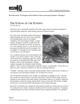
GETTING ACQUAINTED
1
2
4
8
3
5
6
7
10
11
9
q Antenna connector
Connect an (optional) antenna here.
w Rotary encoder
Rotate this encoder to activate its programmable
function. (System or Group Up/ Down in Trunking
Format, and Group or Channel Up/ Down in
Conventional Format.) For further details, contact
your dealer.
10
e POWER switch/ VOLUME control
Turn clockwise to switch ON the transceiver. Rotate
to adjust the volume. Turn counterclockwise fully to
switch OFF the transceiver.
r Transmit/ Battery low indicator
This red LED lights during transmission. If
programmed by your dealer, when the battery pack
power is low, the LED flashes during transmission.
Replace or recharge the battery pack.
t Auxiliary (orange) key
Press to activate its auxiliary function {page 13}.
y Battery pack safety catch
Flip this catch to prevent accidentally pressing the
battery pack release latch. See “INSTALLING/ REMOVING
THE (OPTIONAL) RECHARGEABLE BATTERY PACK OR ALKALINE
BATTERY CASE” on page 6.
u Battery pack release latch
Press this latch to release the battery pack. See
“INSTALLING/ REMOVING THE (OPTIONAL) RECHARGEABLE
BATTERY PACK OR ALKALINE BATTERY CASE” on page 6.
i PTT (Push-To-Talk) switch
Press this switch, then speak into the microphone to
call a station.
o Side 1, Side 2 keys
Press to activate their auxiliary functions {page 13}.
!0 S, A, tB, and Cs
s keys
Press to activate their auxiliary functions {page 13}.
!1 Universal connector
Connect the (optional KMC-25) speaker/ microphone
here. Otherwise, keep the supplied cover in place.
11
DISPLAY
MON SVC SCN LO
Indicator
Description
Displays the channel or group number in
conventional mode and the system or group
number in trunking mode.
Appears when performing Priority Scan.
MON
Appears when the key programmed as Monitor is
pressed.
SVC
This icon is not used on this transceiver.
SCN
Appears when performing Scan.
LO
Appears when the key programmed as RF Power
LO is pressed.
Appears while using the telephone system.
Appears when you have a message.
Displays the group name or the system/ group
number with up to 10 digits. The remaining 2 digits
are used for various indicators.
12
PROGRAMMABLE AUXILIARY FUNCTIONS
Keys w, t, i and o {pages 10 and 11} can be
programmed with the auxiliary functions listed in the
following table. The keys can only be programmed with
functions, depending on whether you are using
Conventional Format or Trunking Format. Please
contact your dealer for further details on these functions.
Function
Auto Telephone
Channel Down
Channel Up
Channel Up/Down 1
Display Character
DTMF ID (BOT)
DTMF ID (EOT)
Emergency 2
Group Down
Group Up
Group Up/Down 1
Home Channel
Home Group
Key Lock
Lamp
Memory (RCL/STO)
Memory (RCL)
Memory (STO)
Message Mode 3
Conventional
Format
Trunking
Format
No
Yes
Yes
Yes
Yes
Yes
Yes
Yes
Yes
Yes
Yes
Yes
No
Yes
Yes
Yes
Yes
Yes
Yes
Yes
No
No
No
Yes
Yes
Yes
Yes
Yes
Yes
Yes
No
Yes
Yes
Yes
Yes
Yes
Yes
Yes
13
1
2
3
4
Function
Conventional
Format
Trunking
Format
Monitor Momentary
Monitor Toggle
None
Operator Selectable Tone
Redial
RF Power Low
Scan
Scan Del/Add
Scan Temporary Delete
SP Attenuation 4
Squelch Level
Squelch Off Momentary
Squelch Off Toggle
System Down
System Up
System Up/Down 1
Talk Around
Telephone Disconnect
Yes
Yes
Yes
Yes
Yes
Yes
Yes
Yes
No
Yes
Yes
Yes
Yes
No
No
No
Yes
No
Yes
Yes
Yes
No
Yes
Yes
Yes
Yes
Yes
Yes
No
Ye s
Yes
Yes
Yes
Yes
No
Yes
These functions can be programmed only on key w, the
encoder.
This function can be programmed only on key t, the
Auxiliary (orange) key.
This function can be programmed only on key o’s A key.
This function can be programmed only on the programmable
function key of the optional KMC-25 speaker/ microphone.
14
OPERATION OVERVIEW
Your dealer can program your transceiver for either
Trunking Format or Conventional Format.
TRUNKING FORMAT
This format can handle up to 32 systems with up to 250
groups in each system. The transceiver can be used in
both trunked mode and conventional mode. Systems,
groups, and their functions are programmed by your
dealer.
CONVENTIONAL FORMAT
This format can handle up to 250 groups with 250
channels in each group. The transceiver can be used
only in conventional mode. Groups, channels, and their
functions are programmed by your dealer.
15
OPERATING BASICS
SWITCHING POWER ON/ OFF
Turn the Power switch/ Volume control clockwise to
switch the transceiver ON.
Turn the Power switch/ Volume control counterclockwise to switch the transceiver OFF.
ADJUSTING THE VOLUME
Rotate the Power switch/ Volume control to adjust the
volume. Clockwise increases the volume and counterclockwise decreases it.
SELECTING A SYSTEM/ GROUP/ CHANNEL
Select the desired system and group (Trunking Format)
using the encoder and the keys programmed with
System or Group Up/ Down.
Select the desired group and channel (Conventional
Format) using the encoder and the keys programmed
with Group or Channel Up/ Down.
16
TIME-OUT TIMER (TOT)
The purpose of the Time-out Timer is to prevent any
caller from using a channel for an extended period of
time.
If you continuously transmit for a period of time that
exceeds the programmed time, the transceiver will stop
transmitting and an alert tone will sound. To stop the
tone, release the PTT switch.
Your dealer can program the TOT time in the range of 15
seconds to 10 minutes.
17
TRUNKED OPERATION (Trunking Format)
PLACING A DISPATCH CALL
1 Select the desired system and group using the
encoder and the System or Group keys.
2 Press the PTT switch, then speak into the
microphone. Release the PTT switch to receive.
•
For best sound quality at the receiving station, hold the
microphone approximately 1.5 inches (3 ~ 4 cm) from
your mouth.
RECEIVING A DISPATCH CALL
1 Select the desired system and group using the
encoder and the System or Group keys. (If the
Scan function has been programmed, you can switch
it ON or OFF as desired.)
2 When you hear the dispatcher’s voice, readjust the
volume as necessary.
18
CONVENTIONAL OPERATION (Trunking Format)
TRANSMITTING
1 Select the desired system and group using the
encoder and the System or Group keys.
2 Press the key programmed as Monitor to check
whether or not the channel is free.
•
If the channel is busy, wait until it becomes free.
3 Press the PTT switch and speak into the
microphone. Release the PTT switch to receive.
•
For best sound quality at the receiving station, hold the
microphone approximately 1.5 inches (3 ~ 4 cm) from
your mouth.
RECEIVING
1 Select the desired system and group using the
encoder and the System or Group keys. (If the
Scan function has been programmed, you can switch
it ON or OFF as desired.)
2 When you hear the dispatcher’s voice, readjust the
volume as necessary.
19
SYSTEM SCAN (Trunking Format)
If the Scan function is programmed, systems can be
scanned by pressing the key programmed as Scan.
When the Scan key is pressed, the SCN indicator and
“-SCAN-” or the revert system/ group number, appear on
the display and scanning starts. The systems not locked
out of the scanning sequence are scanned.
When a call is received, scanning stops and the system
and group digits appear. Press the PTT switch and
speak into the microphone to respond to the call. The
transceiver will continue scanning after a predetermined
time delay if the PTT switch is released and no further
signal is received.
SCANNING TRUNKED SYSTEMS
When scanning trunked systems, the revert groups and
the groups not locked out of the scanning sequence are
scanned. See “GROUP SCAN” on page 22.
Scanning Conventional Systems
When scanning conventional systems, the revert groups
and the groups not locked out of the scanning sequence
are scanned. See “GROUP SCAN” on page 22.
20
SCAN LOCKOUT
If a programmable auxiliary key is programmed with
Scan Del/Add, each system can be locked out of the
scan sequence manually. The delete indicator ( s ) will
appear on the display when the selected system is
locked out.
SCAN REVERT
You can select revert systems and groups using the
encoder and the System or Group keys.
Four types of Scan Reverts which can be programmed
by your dealer are available:
•
Last Called Revert: The last system/ group
received is assigned as the new revert system and
group.
•
Last Used Revert: The last system/ group
responded to is assigned as the new revert system
and group.
•
Selected: The last system/ group selected is
assigned as the new revert system and group.
•
Selected + Talkback: If the system/ group has been
changed during Scan, the newly selected system/
group is assigned as the new revert system and
group. The transceiver “talks back” on the current
receive group.
21
GROUP SCAN (Trunking Format)
Group Scan is available for both trunked and
conventional systems. This feature is useful when more
than one group is programmed in a system. Group
Scan is set by your dealer on request. It scans the
revert groups as well as groups that are allowed to be
scanned.
When a call is received, the group indicator shows the
group number, and that group becomes the revert group.
Simply press the PTT switch to respond to the call.
You can also perform Group Scan while using a priority
channel. Please contact your dealer for information
concerning Priority Scan.
22
CONVENTIONAL OPERATION (Conventional Format)
TRANSMITTING
1 Select the desired group and channel using the
encoder and the Group or Channel keys.
2 Press the key programmed as Monitor to check
whether or not the channel is free.
•
If the channel is busy, wait until it becomes free.
3 Press the PTT switch and speak into the
microphone. Release the PTT switch to receive.
•
For best sound quality at the receiving station, hold the
microphone approximately 1.5 inches (3 ~ 4 cm) from
your mouth.
Receiving
1 Select the desired group and channel using the
encoder and the Group or Channel keys. (If the
Scan function has been programmed, you can switch
it ON or OFF as desired.)
2 When you hear a caller’s voice, readjust the volume
as necessary.
23
SCAN (Conventional Format)
If the Scan function is programmed, groups or channels
can be scanned by pressing the key programmed as
Scan. Scan can be used as either Single Scan or Multi
Scan. Single Scan monitors only the channels of a
single group. Multi Scan monitors all channels of every
group. When the Scan key is pressed, the SCN
indicator and “-SCAN-” or the revert group/ channel
number, appear on the display and scanning starts.
When a call is received, scanning stops and the group
and channel digits appear. Press the PTT switch and
speak into the microphone to respond to the call. The
transceiver will continue scanning after an adjustable
time delay, if the PTT switch is released, and no further
signal is received.
When the displayed group is not locked out of the
scanning sequence, the add indicator ( ) will appear on
the display.
PRIORITY SCAN
The priority channel must be programmed in order for
Priority Scan to function.
The transceiver will automatically change to the priority
channel when a signal is received on it, even if a signal
is being received on a normal channel.
The indicator appears when the displayed channel is
the priority channel.
24
2-TONE SIGNALLING (Conventional Format)
2-Tone Signalling is either activated or deactivated by
your dealer.
2-Tone Signalling only opens the squelch when the
transceiver receives two tones corresponding to those
set up in the transceiver. When the squelch opens, you
will be able to hear the caller without any further action.
After a correct 2-Tone signal is received and the squelch
opens, pressing the key programmed as Monitor will
cancel the connection.
If your dealer programmed Transpond for 2-Tone
Signalling, your transceiver will automatically send an
acknowledgment signal to the station that called you
with the correct 2-Tone signal. Transpond does not
function when you are called as a Group call.
If your dealer programmed Tone Alert for 2-Tone
Signalling, your transceiver will emit a beep when the
correct 2-Tone signal is received.
Note: This transceiver is only capable of decoding 2-Tone Signals. It
cannot encode a 2-Tone Signal.
25
FleetSync™: ALPHANUMERIC 2-WAY PAGING FUNCTION
FleetSync™ is an Alphanumeric 2-way Paging Function,
and is a protocol owned by KENWOOD Corporation.
FleetSync™ enables a variety of paging functions on your
transceiver, some of which depend on dealer programming.
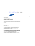
KEY FUNCTIONS
Key
Function
A
Press to change the transceiver mode as shown in
the diagram below.
S
Press while in Stack Mode to toggle between the
received message and the caller’s ID. Press and
hold for more than 1 second to delete the
displayed message.
Press to stop auto-scrolling received messages.
tB, Cs
s
Also press to scroll manually.
PTT
Press to initiate a call.
Normal Operating Mode
Press A
or receive
a Selcall
Receive
a new
message
Selcall Mode *
Hold A for
Press 1 second
any key
New Message
Display Mode
Press
A
Stack Mode
Press A
Press
A
Status Mode
Hold A for 1 second
* Depending on how your dealer programmed the transceiver,
Selcall Mode may be skipped or the transceiver may exit Selcall
Mode automatically (as shown by the dash arrow).
26
SELCALL (SELECTIVE CALLING)
A Selcall is a voice call to a particular station or to a
group of stations.
■ Transmitting
1 Select your desired system and group (or group
and channel).
2 Press the A key to enter Selcall Mode.
3 Use the encoder to select the ID of the station
you want to call.
4 Press the PTT switch and begin your
conversation.
■ Receiving
An alert tone will sound, the transceiver will
automatically enter Selcall Mode, and the calling
station’s ID will appear when a Selcall is received.
To respond to the call, press the PTT switch and
speak into the microphone.
27
■ View the Caller IDs in the Stack Memory
The mail icon ( ) will flash when a Selcall call is
received and stacked.
1 Press and hold the A key for more than 1 second
to enter Stack Mode.
•
The last received Caller ID is displayed with the
Caller ID number. “I” (ID) appears with the number.
2 Use the encoder to select the ID you want to
view (if more than one ID is stored in the stack
memory).
3 To erase the ID, press and hold the S key for
more than 1 second.
■ Identification Codes
An ID code is a combination of a 3-digit Fleet
number and a 4-digit ID number. Each transceiver
must have its own Fleet and ID number.
•
•
•
•
•
Enter a Fleet number (100 ~ 349) to make a group call.
Enter an ID number (1000 ~ 4999) to make an
individual call in your fleet.
Enter a Fleet number followed by an ID number to
make an individual call in your desired fleet
(Inter-fleet call).
Select “ALL” Fleet and “ALL” ID to make a call to all
units (Broadcast call).
Select “ALL” Fleet and enter an ID number to make a
call to the selected ID in all fleets (Supervisor call).
Note:
◆ Broadcast and Supervisor calls are programmed functions
that cannot be made with a keypad.
◆ The ID range may be limited by programming.
28
STATUS MESSAGE
You can send and receive 2-digit Status messages
(10 ~ 79) which may be decided in your talk group.
Messages can contain up to 16 alphanumeric
characters.
A maximum of 9 received messages can be stored in
the stack memory of your transceiver. These saved
messages can be reviewed after reception. If the stack
memory is full, the oldest message will be erased when
a new message is received. The mail icon ( ) lights
when a message is stored in the stack memory.
Note: All stored messages will be cleared when the transceiver
power is turned OFF.
■ Transmitting
1 Select your desired system and group (or group
and channel).
2 Press the A key to enter Selcall Mode.
s key to select the ID of
3 Press the tB key or Cs
the station you want to call.
4 Press the A key to enter Status Mode.
s key to select the status
5 Press the tB key or Cs
you want to transmit.
6 Press the PTT switch to initiate the Status call.
•
“COMPLETE” is displayed when the call has been
successfully transmitted.
29
■ Receiving
The mail icon ( ) will flash and a calling ID or text
message will appear when a Status call is received.
•
The display alternates between the caller ID and the
message.
Press any key to return to Normal Operation Mode.
■ Reviewing the Messages in the Stack Memory
1 Press and hold the A key for more than 1 second
to enter Stack Mode.
•
The last received message is displayed with the
message number. “S” (Status) appears with the
number.
2 Use the encoder to select the message you want
to view (if more than one message is stored in the
stack memory).
s key to stop the
3 Press the tB key or Cs
message from auto-scrolling if desired. Also use
these keys to scroll through the message
manually.
4 Press the S key to toggle between the message
and the caller’s ID.
5 To erase the message, press and hold the S key
for more than 1 second.
30
■ Automatic Status Response
If you pre-select a status number and then leave the
transceier in Status Mode, the transceiver will
automatically respond with that status number when
a request from the base station is received. (The
base station request function is optional.)
OPTIONAL SHORT MESSAGES FEATURE
Received short messages (maximum of 48 characters)
are displayed the same as Status messages {page 28},
however only 4 short messages can be stored in the
stack memory. “M” (Message) and the message number
appear with the message.
31
AUDIBLE USER FEEDBACK TONES
The transceiver emits various tones to indicate the
transceiver’s operating status. Contact your dealer for
further information on these tones.
Tone
Alert
Busy
Delay
Deny
Free System Ring Back Mode/
System Search Mode
Group Call
Individual Call
Intercept
Key Input Error
Key Press [A]
Key Press [B]
Key Press [C]
Password Agreement
Power ON
Pre Alert
Proceed
Queue
Ringing
Roll Over
System Search
System Search End
32
Conventional
Format
Trunking
Format
Yes
Yes
No
No
Ye s
Yes
Yes
Yes
No
Yes
Yes
Yes
No
Yes
Yes
Yes
Yes
Yes
Yes
Yes
No
No
No
Yes
No
No
Yes
Yes
Yes
Yes
Yes
Yes
Yes
Yes
Yes
No
Yes
Yes
Yes
Yes
Yes
Yes