1
Last Updated November 9, 2007
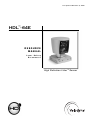
HDL™- 64E
RESOURCE
MANUAL
Laser Safety
Parameters
High Definition Lidar™ Sensor
Ta b l e o f C o n t e n t s
Introduction . . . . . . . . . . . . . . . . . . . . . . . . . . . . . . . . . . . . . . . . . . . . . . . . . . . . . . .3
Forward . . . . . . . . . . . . . . . . . . . . . . . . . . . . . . . . . . . . . . . . . . . . . . . . . . . . . . . . .3
PART 1: Manufacturer and Report Identification . . . . . . . . . . . . . . . . . . . . . . . . . . . . . .5
PART 2: Product and Model Identification . . . . . . . . . . . . . . . . . . . . . . . . . . . . . . . . . .6
PART 3: Compliance with the Labeling Requirements . . . . . . . . . . . . . . . . . . . . . . . . . .7
PART 4: Compliance with the Informational Requirements . . . . . . . . . . . . . . . . . . . . . . .9
PART 5: Description of the Product . . . . . . . . . . . . . . . . . . . . . . . . . . . . . . . . . . . . .10
PART 6: Levels of Accessible Laser Radiation and Classification of the Laser Product . . .12
PART 7: Compliance with the Performance Requirements . . . . . . . . . . . . . . . . . . . . . .22
PART 8: Quality Control Tests and Testing Procedures . . . . . . . . . . . . . . . . . . . . . . . .30
PART 9: Life and Endurance Testing . . . . . . . . . . . . . . . . . . . . . . . . . . . . . . . . . . . . .31
PART 10: Instrumentation and Calibration . . . . . . . . . . . . . . . . . . . . . . . . . . . . . . . . .36
Appendix A: HDL-64E User’s Manual . . . . . . . . . . . . . . . . . . . . . . . . . . . . . . . . . . . .37
Appendix B: Manufacturer’s Laser Diode Specification . . . . . . . . . . . . . . . . . . . . . . . . .56
Appendix C: Inspection Check List . . . . . . . . . . . . . . . . . . . . . . . . . . . . . . . . . . . . . .62
INTRODUCTION
The scope of this report is to submit this report to the Food and Drug Administration for laser
array approval. This Product consists of a 64-piece laser array that is mountable on top of a
vehicle. The array revolves around an axis sending out laser beams to collect terrain data. This
terrain data is used for obstacle detection during a vehicle excursion.
FOREWORD
In recent years, LASER (Light Amplification by Stimulated Emission of Radiation) devices have
become less expensive and more commonplace. Lasers are used in supermarket scanners, CD
and DVD players, construction and surveying instruments, laser pointers for presentations, and
for other medical and industrial purposes. Also, lasers are often used outdoors as part of
orchestrated laser light shows at theme parks, casinos, and special events. Lasers have become
a ubiquitous part of consumer electronics.
In the United States, laser safety is dealt with by regulations, which are part of federal law.
How Lasers are Classified:
The level of a laser hazards in a product is defined by the Class the laser falls in.
Class I is non-hazardous and Class IV is the most hazardous. There are two classifications to
consider:
• the Class of the product (how much laser radiation is accessible to the user) and
• the Class of the radiation (how much laser radiation is accessible to service personnel).
The Class of the product is based upon the amount of laser radiation accessible to the user
during normal operation of the product. Although a product may be classified as Class I, the
product may incorporate a Class I, IIa, II, IIIa, IIIb or Class IV laser diode internally. This is the
laser radiation accessible to service personnel during a service function.
For example, a laser product such as a copy machine could have Class I laser radiation
accessible to the user. Inside the product there could be Class IV laser radiation accessible to
service personnel.
The principal concern for people is the possibility of being illuminated with a laser duringnormal
operations. Exposure to relatively bright light such as a laser, when the eye is adapted to lowlight levels, can result in temporary visual impairment. Visual effects can last from several
seconds to several minutes.
The Food and Drug Administration (FDA) has authority to regulate light-emitting products and
electronic product radiation. The FDA regulates lasers under their "Performance Standards for
Light-Emitting Products". This FDA standard utilizes the American National Standard Institute
(ANSI Z136.1) recommended Maximum Permissible Exposure (MPE), to prevent ocular tissue
damage in allapplications. The MPE is used to calculate the Nominal Ocular Hazard Distance
(NOHD), which is the distance of a laser beam beyond which an individual may be exposed without
risk of ocular tissue damage.
-3-
Every product using lasers has to be designed to ensure that it operates in accordance with best
practice with regard to the safety of lasers, LEDs and other optical hazards in order to minimize
the risk of personal injury to staff or third parties.
In order to do this, one written report, as comprehensive as possible, is submitted to FDA for
final evaluation. FDA will make it sure that it is following the correct procedures and taking the
necessary precautions as laid down by the various standards.
FDA will test and certify the prototype or completed product to the appropriate standard or
standards and provide a full test report including details of:
• Measurement test results
• Accessible emission limits
• Required engineering controls
• Required labeling
• Required information in user’s manual and product brochures
• Failure modes of drive electronics and other reasonably foreseeable failures affecting
safety
In the United States, compliance with the regulations for lasers and laser products issued by the
Center for Devices and Radiological Health (CDRH) of the Food and Drug Administration (FDA) is
mandatory. The current CDRH regulations pertaining to laser emissions are found in 21 CFR
1040.10 and 1040.11. CDRH, which is part of FDA, has the task of enforcing the regulations.
The laser product regulation is known as 21 CFR 1040.10 . This document represents the full
completion of 21 CFR 1040.10 and 1040.11, and the calculations performed in this document
were based on IEC standard 60285-1.
Obstacle Detection and Avoidance Systems are very effective electronic navigation systems.
There are different working principles and among these are LASER based systems that are used
by the described prototype.
This system consists of a 64 infrared lasers mounted on top of a vehicle. The system revolves
around an axis sending out laser beams to collect terrain data. This terrain data is used for
obstacle detection during a vehicle excursion.
IR laser diodes are pulsed diodes and the stated power rating is peak. While they have "high"
peak power ratings, the average power ratings are typically less than 1mW as they must run at
a very low duty cycle. They are suitable for rangefinder or similar applications. These laser
diodes come in plastic packages that look much like LEDs and, since there is limited opportunity
for cooling the devices and overheating is a concern, power dissipation is one of the major
limiting factors. This has an important side benefit of making the product safe by guaranteeing
continuous low power.
The Detection System described in the following report is using pulsed laser diodes activated with
a very low duty cycle, making the entire system a safety class I product. The following Product
Report contains construction and performance details describing how the Laser Obstacle
Detection and Avoidance System fully complies with the FDA safety regulations.
-4-
LASER PRODUCT REPORT
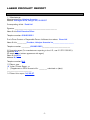
PART 1: MANUFACTURER AND REPORT IDENTIFICATION
1.1 Manufacturer:
Manufacturing Firm Velodyne Acoustics
Address 345 Digital Drive, Morgan Hill, CA 95037
Corresponding official: David Hall
Signature _____________________________________________________
Name & title Chief Executive Officer
Telephone number 408-465-2821
Firm's Prime Contact or Responsible Person if different from above: Bruce Hall
Name & title ____________President, Velodyne Acoustics Inc__________________________
Telephone number ___________408-465-2800___________________________________
1.2 Importing agent (For manufacturers exporting to the U.S., see 21 CFR 1005.25.):
Signature N/A
(Or attach copy of written agreement with agent)
Name & title N/A
Address N/A
Telephone number N/A
1.3 Report type:
( X ) Laser Product Report, or
(
) Supplement to CDRH Accession No. __________ submitted on (date)
_______________________________
1.4 Date of this report: 04/26/07
-5-
PART 2: PRODUCT AND MODEL IDENTIFICATION
2.1 List all names, brand names, model numbers and model family designations of the laser
product being reported. If the product is sold by other companies under different brand names,
also give the names and addresses of the companies, the brand names, and the model
numbers, and indicate how the brand names and model numbers correspond with your own
brand names and model numbers.
Product Name: HDL-64E
2.2 Is your laser product the result of the modification of a laser product certified by another
manufacturer? [see 1040.10(i)]
( )Yes
( X )No
If yes, identify the manufacturer(s), brand(s), and model number(s).
_______________________________________________________________
_______________________________________________________________
NOTE: Modification involves any changes to the product that affect its classification,
performance or labeling requirements (as required by the standard or an approved variance).
2.3 Does your laser product incorporate an unmodified, certified laser product?
( )Yes
( X )No
If yes, identify the manufacturer(s), brand(s), and model number(s).
________________________________________________________________
________________________________________________________________
2.4 Does your product incorporate a noncertified laser product?
( )Yes
( X )No
If yes, identify the manufacturer(s), brand(s), model(s), and describe the type of product.
________________________________________________________________
________________________________________________________________
2.5 Does your laser product incorporate a removable laser system or systems as defined in
1040.10(c)(2)?
( )Yes
( X )No
If yes, identify the manufacturer(s), brand(s), and model number(s).
________________________________________________________________
________________________________________________________________
2.6 If the laser product, as introduced into commerce, is not supplied with a laser or laser
system or the product does not incorporate a laser or laser system, report by manufacturer and
model number which laser or laser system, if any, is recommended by you for use with the
product.
N/A
2.7 If you do not recommend a specific laser or laser system for use with the reported product,
state the specifications of the laser or laser system to be incorporated.
N/A
-6-
PART 3: COMPLIANCE WITH THE LABELING REQUIREMENTS
For each of the following labels required for the product being reported, provide a sample or a
facsimile of each label. Clearly indicate the locations on the product of all required labels in your
response to this Part or to Part 5. Reference to diagrams, photographs, blueprints, product
literature, etc., is acceptable. See Compliance Guide, page 7, for assistance.
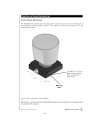
3.1 Certification label - Required on all laser products (1010.2).
Is the label (or a copy) submitted with this report?
( X )Yes
( ) No
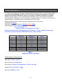
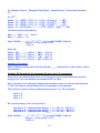
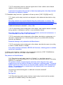
Location on product: __On laser housing. See Figure 1.
FIGURE 1
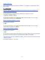
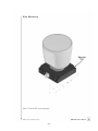
3.2 Identification label - Required on all laser products (1010.3).
Is the label (or a copy) submitted with this report?
( X )Yes
( )No
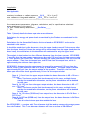
Location on product: __On laser housing____________________________
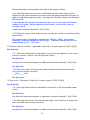
See Figure 2.
FIGURE.2
3.3 Warning logotype - Required on Class II, III, and IV laser products. [1040.10(g)(1),
(2),(3),(4),(8),(9),(10)].
Is the label (or a copy) submitted with this report?
( )Yes
( X )No
Location on product: N/A
-7-
3.4 Warning label - Required on Class IIa laser products [1040.10(g)(1)(i)].
copy) submitted with this report?
( )Yes
( X )No
Location on product: N/A
Is the label (or a
3.5 Aperture label(s) - Required on Class II, III and IV laser products [1040.10(g)(5),(8),(9),(10)
or 1040.11(a)(3)].
Are the label(s) (or copies) submitted with this report?
( )Yes
( X )No
Location on product: N/A
3.6 Label(s) for noninterlocked protective housings [1040.10(g)(6),(8),(9),(10)]. Are the label(s)
(or copies) submitted with this report?
( )Yes
( X )No
Location on product: ___________________________________________
Are the label(s) visible both prior to and during opening or removal of housing?
( )Yes
( X )No N/A
3.7 Label(s) for defeatably interlocked protective housings [1040.10(g)(7),(8),(9),(10)].
Are the label(s) (or copies) submitted with this report?
( )Yes
( X )No N/A
Location on product: _ This laser product contains non-defeatable interlocks__
Are the label(s) visible both prior to and during interlock defeat?
( )Yes
( X )No N/A
3.8 Label(s) for optionally interlocked protective housings. (See Laser Notice of March 2, 1977,
dealing with optional interlocks.) Is the label (or a copy) submitted with this report?
( )Yes
( X )No
Location on product: __N/A_________________________________________
Are labels visible both prior to and during opening or removal of the housing?
( )Yes
( X )No
NOTE: If the labeling requirements are inappropriate to your product, you may apply for
approval of alternate labeling. See sections 1010.2, 1010.3, and 1040,10(g)(10).
-8-
PART 4: COMPLIANCE WITH THE INFORMATIONAL REQUIREMENTS
4.1 Submit copies of user and servicing information (operator and service manuals) for your
laser product. If the manuals are very extensive, submit those portions that confirm compliance
with Section 1040.10(h) [and 1040.11(a)(2), if a medical laser product] and that permit
understanding how your laser product functions. See Compliance Guide, page 8, for assistance.
Are copies of user and service information attached to this report?
( )Yes
( X )No
If "Yes," please identify attachment: ___________
If "No," please explain why not
A User’s Manual is attached as Appendix A
NOTE: These materials may also be used in the product description required by Part 5.
4.2 Submit copies of any catalogs, specification sheets, and descriptive brochures for Class IIa,
II, III, and IV laser products.
Are copies of catalogs, specification sheets, or brochures attached to this report?
( )Yes
( X )No
If "Yes," please identify attachment:___________
If "No," please explain why not
This Product is a Class 1M device.
-9-
PART 5: DESCRIPTION OF THE PRODUCT
5.1 Describe the product and its function. You may refer to brochures and manuals submitted
with this report. Please include drawings or photographs adequate to document compliance of
the product with the performance and labeling requirements.
Is a product description attached to this report?
( X )Yes
( )No
Please identify attachment: _____________________
The product consists of 64-piece laser array that is mountable on top of a vehicle. The
array revolves around an axis sending out laser beams to collect terrain data. This terrain
data is used for obstacle detection.
The product is comprised of 4 Laser Assemblies consisting of 16 Lasers each (totaling 64
lasers). Two Laser Assemblies are located in the upper plane (which are referred to as
Upper Left Head and Upper Right Head) and two Laser Assemblies located in a lower plane
(referred to as Lower Left Head and Lower Right Head). The Lower Heads are oriented so
that aimed at the ground near the product. The Upper Heads are oriented so that these
laser pulses are substantially directed also towards the ground, but to a further distance
than the Lower Heads.
Initially, two lasers in each of the upper heads are pulsed (for example Lasers 1 and 2). The
optical pulse duration is approximately 5 nanoseconds. Four microseconds later (250 kHz
burst frequency), two other lasers (Lasers 3 and 4) in each of the upper head are pulsed.
Four microseconds later, two other lasers (Lasers 5 and 6) are triggered. This process
repeats until all 16 lasers have been pulsed. The overall period for this sequencing of the
laser pulses is 32 microseconds. This process of sequentially pulsing the 16 lasers in each
of the upper heads repeats two additional times (for a total of three cycles).
After these three cycles in the upper head, a single sequencing cycle is conducted for the
Lower Heads. At the completion of this cycle, the loop repeats (3 Upper Head Cycles then 1
Lower Head cycle).
While transmitting laser pulses, the product will rotate at a rate of approximately 600
revolutions per minute (10 revolutions per second).
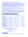
5.2 Describe the external and internal laser radiation fields and paths. Beam path diagrams
indicating protective housing, beam attenuators, viewports, scanners, targets, etc. would be
helpful. Please identify external and internal laser power or energy levels where applicable.
Are description and diagrams of the laser radiation fields and paths attached?
( X )Yes
( )No
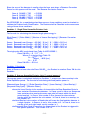
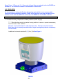
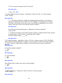
Please identify attachment: ___See Figure 3
- 10 -
FIGURE 3
DEPICTION OF THE PRODUCT LASER EMISSION
5.3 List the procedures performed during operation and indicate those collateral and laser
radiation fields specified in Part 6 to which human access is possible when those procedures are
being performed. [See definition of human access - Section 1040.10(b)(15)].
Operational procedures and accessible radiation:
When power is applied to the HDL-64E, the Product will begin to rotate. Once a minimum
rotational speed is achieved, the Lasers will be allowed to transmit. This rotation speed is
monitored by an accelerometer and comparator circuit. The typical minimum speed of
rotation before the lasers begin to transmit is 300 revolutions per minute.
The peak power emitted by each laser is controlled using a DSP controlled pulse charging
circuit. In addition, the power supplies used to provide this pulse charge are limited in the
amount of charge they can provide in the system. So, typically, the Product can only operate
the lasers at approximately half of their rated maximum power (45 watts). To provide
margin in the safety calculations, this number has been raised to two-thirds of the rated
maximum power (60 watts)
Laser radiation is only possible when the Product is rotating at the above mentioned
minimum rate. When radiating, the Laser emissions only occur through the Product’s output
window.
5.4 List the procedures performed during maintenance and indicate those collateral and laser
radiation fields specified in Part 6 to which human access is possible when those procedures are
being performed. See the definition of maintenance in section 1040.10(b)(24) and Compliance
Guide, page 5.
Maintenance procedures and accessible radiation:
No maintenance allowed by the user on this product.
5.5 List the procedures performed during service and indicate those collateral and laser
radiation fields specified in Part 6 to which human access is possible when those procedures are
being performed.
Service procedures and accessible radiation:
No service allowed by the user on this product.
- 11 -
PART 6: LEVELS OF ACCESSIBLE LASER RADIATION AND CLASSIFICATION
OF THE LASER PRODUCT
6.1 Give the specifications of all laser radiation fields described in Part 5 to which human access
is possible during operation. See Section 1040.10(e) for measurement parameters. Indicate
whether the values are measured or based on calculations. Whether measured or calculated,
please provide a diagram of your measurement/calculation set-up, and pertinent dimensions
such as separation distances, source and detector aperture size, etc. in order to show how your
measurements or calculations are in accordance with 1040.10(e).
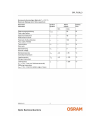
Please provide as much of the following as is appropriate to your product:
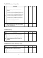
wavelength(s): 905 nm
maximum average radiant power: Get from Table 1 Below
beam divergence: 3.5 mrad horizontally
0.5 mrad vertically
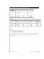
Using the 30 to 100 foot data from Table 1
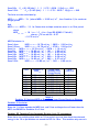
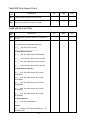
The beam spot size varies with distance from the Product. Table 1 shows the beam spot
size and area versus distance FORM THE Product’s output window.
Distance
14 mm
100 mm
1 foot
5 feet
10 feet
16 feet
20 feet
25 feet
30 feet
100 feet
Beam
Width(mm)
16.0
17.0
16.1
14.5
12.9
15.4
16.0
20.6
25.2
101.6
Beam
Height(mm)
45.0
43.0
31.5
14.6
10.8
8.5
7.8
9.3
9.7
20.3
Beam Area
(mm2)
720.0
731.0
507.2
211.7
139.3
130.9
124.8
191.6
244.4
2062.5
TABLE 1
LASER SPOT SIZE vs DISTANCE
Pulsed Operation Characteristics:
peak power: 60 W, maximum
pulse durations: 5 nanoseconds
pulse energy: 60 watt x 5 nanoseconds = 300 nJ per laser
repetition rate: 31.25 khz / 32µs
burst rate: 250 kHz / 4 us
- 12 -
if applicable:
Not Applicable
maximum irradiance or radiant exposure: __N/A____ W or J cm-2
max. radiance or integrated radiance: ___N/A__ W or J cm-2 sr-1
________________________________________________________________
Are measurement parameters, diagrams, calculations, and/or specifications submitted
as an attachment to this report?
( X )Yes - Please identify attachment: ___See Below______
( )No
Table 1 (above) details the beam spot size versus distance.
Calculations for energy and power levels transmitted by the Product are conducted in this
section.
Calculations for the Accessible Emission Limit are based on IEC 60285-1 and are also
attached in this section.
It should be noted that is this document, since the upper heads transmit 3 times more often
than the lower head (so 3 times the energy will be transmitted from the upper head than the
lower head), the calculations in this document will conducted for only the upper head.
The analysis is also broken into four different distances from the laser sources. IEC 608251 specifies that the laser power measurement be made 100 mm from the laser source using
a 7 mm aperture (for Class 1M). We also conduct the safety calculations 100 mm from the
output window, 1 foot from the output lens, and 20 feet from the output lens, which is
approximately the minimum laser spot size.
IEC 60285-1 dictates that the output power (or energy) be measured 100 mm from the
source, which in this product’s case is an array of laser diodes. The upper head is located
approximately 86 mm from the output window of the product. Therefore, the first laser
beam spot size will be check approximately 14 mm for the output window.
Case a) 14 mm from the upper output window the beam dimension is 45 x 16 mm =
720 mm2
Note: Two lasers may be fired simultaneously in this case, and both lasers
overlap the stated beam dimension, so the power calculations will be doubled
for this case.
Case b) At 100 mm from the upper output window, the beam dimension is 43 x 17
mm = 731 mm2
Note: Two lasers may be fired simultaneously in this case, and both lasers
overlap the stated beam dimension, so the power calculations will be doubled
for this case.
Case c) At 12 inches (304.8mm) from output lens, the dimension is 31x14.5mm =
507.2 mm2
Case d) At 20 feet (6096 mm) from the output lens, the beam diameter is 8x16mm
= 124.8mm2
Case d is the minimum spot size outside the lens.
Per IEC 60285-1, a receiver with 7mm diameter shall be used to measure the output power
form the Product. This 7 mm diameter detector will have a surface of 38.465mm2
- 13 -
Since the area of the detector is smaller than the laser spot sizes, a Detector Correction
Factor for this aperture will be used. This Detector Correction Factor is:
Case
Case
Case
Case
a)
b)
c)
d)
38.465
38.465
38.465
38.465
/
/
/
/
720
731
507.2
124.8
=
=
=
=
0.0534
0.0526
0.0758
0.3082
Per IEC 60285, for a repetitively pulsed laser source, three conditions must be checked to
validate the Product Laser Classification. The Product shall be Classified as the worst case
rating of these three conditions.
Condition 1: Single Pulse Accessible Emission Limit
The formula for calculating the detected single pulse energy is:
[Peak Power] * [Pulse Width] * [Number of Lasers Overlapping] * [Detector Correction
Factor]
Case
Case
Case
Case
a:
b:
c:
d:
Detected
Detected
Detected
Detected
Laser
Laser
Laser
Laser
EnergySP
EnergySP
EnergySP
EnergySP
=
=
=
=
60
60
60
60
[W]
[W]
[W]
[W]
*
*
*
*
5
5
5
5
[ns]
[ns]
[ns]
[ns]
*
*
*
*
2
2
1
1
*
*
*
*
.0534
.0526
.0758
.3082
=
=
=
=
32.0
31.6
22.7
92.5
nJ
nJ
nJ
nJ
The single pulse AEL is calculated from Table 4 of IEC 60285-1,
Class 1M AELSP = 2 * 10-7 * C4
Where C4 is derived from Table 10:
C4 = 100.002*( _- 700)
Where _ = 905 [nm]
C4 = 2.57
Class 1M AELSP = 514 nJ
Condition 1 Conclusion
Since all Cases are lower than the Class 1M AELSP, the Product is rated as Class 1M for this
Condition.
Condition 2: Average Accessible Emission Limit (1 second exposure)
The average power is calculated similarly to Condition 1, except more lasers overlap in the
Pulse Repetition period. The formula for calculating the fixed position power is:
[Detected Laser EnergySP] * [Pulse Repetition Rate] * [Laser Overlap] * [Head Overlap] *
[Sequential Duty Cycle] * [Rotation Factor]
where the Laser Overlap is the number of times within the Base Repetition Period a
laser emission illuminates the detector. In Cases a and b, there are 8 separate
laser emissions that overlap the same spot size (all lasers within the burst
period overlap). In Case c, this number is 3 to account for the maximum
overlap within the head as the unit rotates. In Case d, there is no overlap, so
this number is 1.
the Head Overlap is the number of Heads that will cross the fixed position detector in
a single rotation. In Cases a, b and c, this number is 2. In Case d, there is no
overlap of left and right heads, so this number is 1.
the Sequential Duty Cycle is how often the Upper Head of the Product is triggered in
the system operation. This number is 0.75.
- 14 -
and the Rotation Factor is the ratio of laser spot size to the circumference at the
given distance form the output window.
Rotation Factor = [Spot Width] / [Circumference of Detector Distance of Center of Rotation]
The Rotation Factors are:
Case
Case
Case
Case
Case
mW
Case
mW
Case
mW
Case
mW
a:
b:
c:
d:
16
17
16.1
16
[mm]
[mm]
[mm]
[mm]
/ { 2 * * (86 + 14 [mm] }
=
/ { 2 * * (86 + 100 [mm] }
=
/ { 2 * * (86 + 304.8 [mm] } =
/ { 2 * * (86 + 6096 [mm] } =
.0255
.0145
.0066
.0004
a: Det Laser Powerav,rot =
32.0 [nJ] * 31.25 [kHz] * 8 * 2 * .75 * .0255 = 0.31
b: Det Laser Powerav,rot =
31.6 [nJ] * 31.25 [kHz] * 8 * 2 * .75 * .0145 = 0.17
c: Det Laser Powerav,rot =
22.7 [nJ] * 31.25 [kHz] * 3 * 2 * .75 * .0066 = 0.021
d: Det Laser Powerav,rot =
92.5 [nJ] * 31.25 [kHz] * 1 * 1 * .75 * .0004 = 0.0009
The Class 1M average power AEL is calculated from Table 4 (using 10 s emission duration),
Class 1M AELSP = 3.9 * 10-4 * C4 * C7
Where C4 is derived in Condition 1 = 2.57
And C7 is derived from Table 10 = 1
Class 1M AELav = 1 mW
Condition 2 Conclusion
Since all Cases are lower than the Class 1M AELav, the Product is rated as Class 1M for this
Condition.
Condition 3: Repetitive Pulse Accessible Emission Limit (10 second exposure)
The calculated emission from Condition 1 will be used to check for the Laser Classification for
this Condition.
Case
Case
Case
Case
a:
b:
c:
d:
Detected
Detected
Detected
Detected
Laser
Laser
Laser
Laser
EnergySP
EnergySP
EnergySP
EnergySP
=
=
=
=
32.1
31.6
22.7
92.5
nJ
nJ
nJ
nJ
We must determine the number of laser emissions that will illuminate the detector over a
period of 10 seconds to calculate to AELtrain, SP. This number shall be calculated using the
following formula:
N = [Pulse Repetition Rate] * [Laser Overlap] * [Head Overlap] * [Sequential Duty Cycle] *
[Rotation Factor] * [Illumination Duration]
C5 = N-0.25
However, if multiple optical pulses occur within an Ti (18us period as defined by Table 3),
they are considered as a single pulse to determine N, and the energies of the individual
pulses are added to compared to AEL of Ti . This is the case in Sub-Cases a, b and c. For
these Cases the number is calculate using the following formula.
- 15 -
N = [Rotation Factor] * [Sequential Duty Cycle] * [Head Overlap] * [Illumination Duration] /
[Ti]
C5 = N-0.25
Case
Case
Case
Case
a:
b:
c:
d:
C5
C5
C5
C5
=
=
=
=
{.0255
{.0145
{.0059
{31.25
* 0.75 * 2 * 10 [s] / 18 [us]}-0.25 = .083
* 0.75 * 2 * 10 [s] / 18 [us]}-0.25 = .095
* 0.75 * 2 * 10 [s] / 18 [us]}-0.25
= .119
[kHz] * 1 * 1 * 0.75 *.0004 * 10[s]}-0.25 = .321
The limits are then calculated by:
AELtrain, SP = AELSP * C5 = 514 nJ
AELtrain, SP = AEL18us * C5
Class 1M AEL18us
= 7 * 10-4 * t0.75 * C4 (from IEC 60285-1 Table 4)
Where t = 18 us and C4 = 2.57
= 497 nJ
Class 1M
Case
Case
Case
Case
a:
b:
c:
d:
AELtrain, SP 1M
AELtrain, SP 1M
AELtrain, SP 1M
AELtrain, SP 1M
=
=
=
=
497
497
497
514
nJ
nJ
nJ
nJ
*
*
*
*
.083
.095
.119
.321
= 41.3
= 47.2
= 59.1
= 165.0
nJ
nJ
nJ
nJ
Condition 3 Conclusion
Since all Cases are lower than the Class 1M AELtrain,
this Condition.
SP
, the Product is rated as Class 1M for
Condition 3B: Repetitive Pulse Accessible Emission Limit (18 us exposure)
Since there are multiple pulses within an 18 us period, we must also check that the total
energy in the 18 us period does not exceed the AEL for 18us.
Also, since there is no overlap of multiple laser emissions, there is no burst mode operation
in 18 us for Cases d, so this Case will not be evaluated in this calculation.
The maximum number of laser emissions that can occur in an 18 us period is:
Case a: 5
Case b: 5
Case c: 3
So, the total energy in this 18 us period is:
Sub-Case a: 5 * Detected Laser EnergySP = 5 * 32.1 nJ = 160.5 nJ
Sub-Case b: 5 * Detected Laser EnergySP = 5 * 31.6 nJ = 158.0 nJ
Sub-Case b: 5 * Detected Laser EnergySP = 3 * 22.7 nJ = 68.1 nJ
Class 1M AEL18us
= 7 * 10-4 * t0.75 * C4 (from IEC 60285-1 Table 4)
Where t = 18 us and C4 = 2.57
= 497 nJ
- 16 -
Condition 3B Results
Since all Cases are lower than the Class 1M AEL18us, the Product is rated as Class 1M for
this Condition.
6.1 CONCLUSION
Since the Product meets the Accessible Emission Limits for these three conditions. It is
classified as a Class 1M Product.
6.2 Indicate the Class of the laser product, based on your response to Part 6.1.
( X ) Class I ( ) Class IIa ( ) Class II
( ) Class IIIa ( ) Class IIIb ( ) Class IV
6.3 Give the specifications of all possible laser radiation fields described in Part 5 to which
human access is possible during maintenance.
No user maintenance allowed or required.
Are specifications attached?
( )Yes
( X )No
6.4 Give the specifications of all possible laser radiation fields described in Part 5 to which
human access is possible during service.
No user service allowed or required.
Are specifications attached?
( )Yes
( X )No
6.5 Describe all collateral radiation associated with the product. Report the source(s) and levels
and describe where and under what circumstances such radiation is accessible.
This product does not have any collateral radiation. There is not any circumstance such that
radiation is possible.
Is description attached? ( )Yes ( X )No
- 17 -
6.6
EXTENDED NOMINAL OCCULAR HAZARD DISTANCE (ENOHD)
As this product is rated as a Class 1M product, it is not intended for use with any products
which use viewing optics, such as binoculars. However, if an optic viewing device is used with
this product, the following calculations will determine the distance at which the laser
emission level falls below the Maximum Permissible Exposure (MPE) level. Note that this
level is different than the Accessible Emission Limit (AEL) used in section 6.1. Also, because
these calculations are associated with a viewing optic, the detector aperture is increased to
50mm (as opposed to 7 mm in the previous calculations).
In this calculation we will use the same distance information from section 6.1 (14mm,
100mm, 1 foot and 20 feet from the output window) plus the additional distances of 5 feet,
10 feet, 16 feet, 30 feet and 100 feet.
The calculation from section 6.1 will be repeated for these calculations, with the changes in
aperture size and acceptance levels. Since the detector area is larger than the all laser
spots (except for the laser spot at 100 feet), as shown in Table 1, the Detector Correction
Factor in all cases is 1 (even for the 100 foot case). The case names have also been
changed for better indication of the distance from the output window.
Condition 1: Single Pulse Maximum Permissible Exposure Limit
The formula for calculating the detected single pulse energy density is:
[Peak Power] * [Pulse Width] * [Number of Lasers Overlapping] * [Detector Corr Factor] /
[Spot Area]
Case 4mm: Detected Laser Energy DensitySP = 60 [W] * 5 [ns] * 2 * 1 / .000720 [m2]
= 0.833 mJ/m2
Case 100mm: Detected Laser Energy DensitySP = 60 [W] * 5 [ns] * 2 * 1 / .000731 [m2]
= 0.821 mJ/m2
Case 1ft: Detected Laser Energy DensitySP
= 60 [W] * 5 [ns] * 2 * 1 / .000507 [m2]
2
= 1.183 mJ/m
Case 5ft: Detected Laser Energy DensitySP
= 60 [W] * 5 [ns] * 1 * 1 / .000212 [m2]
2
= 1.417 mJ/m
Case 10ft: Detected Laser Energy DensitySP
= 60 [W] * 5 [ns] * 1 * 1 / .000139 [m2]
2
= 2.153 mJ/m
Case 16ft: Detected Laser Energy DensitySP
= 60 [W] * 5 [ns] * 1 * 1 / .000131 [m2]
2
= 2.292 mJ/m
Case 20ft: Detected Laser Energy DensitySP
= 60 [W] * 5 [ns] * 1 * 1 / .000125 [m2]
2
= 2.404 mJ/m
Case 30ft: Detected Laser Energy DensitySP
= 60 [W] * 5 [ns] * 1 * 1 / .000244 [m2]
2
= 1.227 mJ/m
Case 100ft: Detected Laser Energy DensitySP
= 60 [W] * 5 [ns] * 1 * 1 / .002063
[m2] = 0.146 mJ/m2
The single pulse MPE is calculated from Table A1 of IEC 60285-1,
MPESP = 5 * 10-3 * C4 J/ m2
Where C4 is derived from Table 10:
C4 = 100.002*( _- 700)
Where _ = 905 [nm]
C4 = 2.57
MPESP = 12.85 mJ/ m2
Condition 1 Conclusion
Since all Cases are lower than the MPESP, the Product has no ENOHD for this Condition.
- 18 -
Condition 2: Average Maximum Permissible Exposure Limit (1 second exposure)
The average power is calculated similarly to the ENOHD Condition 1, except more lasers
overlap in the Pulse Repetition period. The formula for calculating the fixed detector position
power is:
[Detected Laser Energy DensitySP] * [Pulse Repetition Rate] * [Laser Overlap] * [Head
Overlap] * [Sequential Duty Cycle] * [Rotation Factor]
where the Laser Overlap is the number of times within the Base Repetition Period a
laser emission illuminates the detector. In Cases 4mm, 100mm and 1ft there
are 8 separate laser emissions that overlap the same spot size (all lasers within
the burst period overlap). In Case 5ft, this number is 2 to account for the
maximum overlap within the head as the unit rotates. In the remaining Cases,
there is no overlap, so this number is 1.
the Head Overlap is the number of Heads that will cross the fixed position detector in
a single rotation. In all Cases less than 20ft, the emissions form the heads
may overlap, so this number is 2. In Cases 20ft and above, there is no overlap
of left and right heads, so this number is 1.
the Sequential Duty Cycle is how often the Upper Head of the Product is triggered in
the system operation. This number is 0.75.
and the Rotation Factor is determined differently from Section 6.1. Since the
detector is larger than the spot size, the ratio of the detector diameter to the
circumference at the given distance from the output window is used.
Rotation Factor = [Detector Diameter] / [Circumference of Detector Distance of Center of
Rotation]
The Rotation Factors are:
Case
Case
Case
Case
Case
Case
Case
Case
Case
14mm:
100mm:
1ft:
50
5ft:
50
10ft: 50
16ft: 50
20ft: 50
30ft: 50
100ft: 50
50 [mm] / { 2 * * (86 + 14 [mm] }
50 [mm] / { 2 * * (86 + 100 [mm] }
[mm] / { 2 * * (86 + 304.8 [mm] } =
[mm] / { 2 * * (86 + 1524 [mm] } =
[mm] / { 2 * * (86 + 3048 [mm] } =
[mm] / { 2 * * (86 + 4876.8 [mm] } =
[mm] / { 2 * * (86 + 6096 [mm] } =
[mm] / { 2 * * (86 + 9144 [mm] } =
[mm] / { 2 * * (86 + 30480 [mm] } =
= .0796
= .0428
.0204
.0049
.0025
.0016
.0013
.0009
.0003
The detected Laser Power Density Calculations is then:
Case 14mm:
Det Laser Powerav,rot = 0.833 [mJ/m2] * 31.25 [kHz] * 8 * 2 * .75 *
.0796 = 24.87 W/m2
Case 100mm:
Det Laser Powerav,rot = 0.821 [mJ/m2] * 31.25 [kHz] * 8 * 2 * .75 *
.0428 = 13.17 W/m2
Case 1ft:
Det Laser Powerav,rot = 1.183 [mJ/m2] * 31.25 [kHz] * 8 * 2 * .75 * .0204
= 9.03 W/m2
Case 5ft:
Det Laser Powerav,rot = 1.417 [mJ/m2] * 31.25 [kHz] * 2 * 2 * .75 * .0049
= 0.66 W/m2
Case 10ft: Det Laser Powerav,rot = 2.153 [mJ/m2] * 31.25 [kHz] * 1 * 2 * .75 * .0025
= 0.26 W/m2
Case 16ft: Det Laser Powerav,rot = 2.292 [mJ/m2] * 31.25 [kHz] * 1 * 2 * .75 * .0016
= 0.17 W/m2
- 19 -
Case 20ft: Det Laser Powerav,rot = 2.404 [mJ/m2] * 31.25 [kHz] * 1 * 1 * .75 * .0013
= 0.07 W/m2
Case 30ft: Det Laser Powerav,rot = 1.227 [mJ/m2] * 31.25 [kHz] * 1 * 1 * .75 * .0009
= 0.02 W/m2
Case 100ft:
Det Laser Powerav,rot = 0.146 [mJ/m2] * 31.25 [kHz] * 1 * 1 * .75 *
.0003 = 0.001 W/m2
The MPE average power Table A1 (using 10 s emission duration),
MPEAV = 10 * C4 * C7 W/m2
Where C4 is derived in Condition 1 = 2.57
And C7 is derived from Table 10 = 1
MPEAV = 25.7 W/m2
Condition 2 Conclusion
Since all Cases are lower than the MPEAV, the Product has no ENOHD for this Condition.
Condition 3: Repetitive Pulse Maximum Permissible Exposure Limit (10 second exposure)
The calculated emission from ENOHD Condition 1 will be used to check for this Condition.
Case
Case
Case
Case
Case
Case
Case
Case
Case
4mm: Detected Laser Energy DensitySP
100mm: Detected Laser Energy DensitySP
1ft: Detected Laser Energy DensitySP
5ft: Detected Laser Energy DensitySP
10ft: Detected Laser Energy DensitySP
16ft: Detected Laser Energy DensitySP
20ft: Detected Laser Energy DensitySP
30ft: Detected Laser Energy DensitySP
100ft: Detected Laser Energy DensitySP
= 0.833 mJ/m2
= 0.821 mJ/m2
= 1.183 mJ/m2
= 1.417 mJ/m2
= 2.153 mJ/m2
= 2.292 mJ/m2
= 2.404 mJ/m2
= 1.227 mJ/m2
= 0.146 mJ/m2
We must determine the number of laser emissions that will illuminate the detector over a
period of 10 seconds to calculate to MPEtrain, SP. This number shall be calculated using the
following formula:
N = [Pulse Repetition Rate] * [Laser Overlap] * [Head Overlap] * [Sequential Duty Cycle] *
[Rotation Factor] * [Illumination Duration]
C5 = N-0.25
However, if multiple optical pulses occur within an Ti (18us period as defined by Table 3),
they are considered as a single pulse to determine N, and the energies of the individual
pulses are added to compared to MPE of Ti . This is the case in Cases 14mm, 100mm and
1ft. For these Cases the number is calculated using the following formula.
N = [Rotation Factor] * [Sequential Duty Cycle] * [Head Overlap] * [Illumination Duration] /
[Ti]
C5 = N-0.25
Case
Case
Case
Case
Case
Case
Case
14mm:
100mm:
1ft:
C5
5ft:
C5
10ft: C5
16ft: C5
20ft: C5
=
=
=
=
=
C5 = {.0796 * 0.75 * 2 * 10 [s] / 18 [us]}-0.25 = .0623
C5 = {.0428 * 0.75 * 2 * 10 [s] / 18 [us]}-0.25 = .0728
{.0204 * 0.75 * 2 * 10 [s] / 18 [us]}-0.25
= .0876
{31.25 [kHz] * 2 * 2 * 0.75 *.0049 * 10[s]}-0.25 = .121
{31.25 [kHz] * 1 * 2 * 0.75 *.0025 * 10[s]}-0.25 = .170
{31.25 [kHz] * 1 * 2 * 0.75 *.0016 * 10[s]}-0.25 = .191
{31.25 [kHz] * 1 * 1 * 0.75 *.0013 * 10[s]}-0.25 = .239
- 20 -
Case 30ft: C5 = {31.25 [kHz] * 1 * 1 * 0.75 *.0009 * 10[s]}-0.25 = .262
Case 100ft:
C5 = {31.25 [kHz] * 1 * 1 * 0.75 *.0003 * 10[s]}-0.25 = .345
The limits are then calculated by:
MPEtrain, SP = MPESP * C5 (where MPESP = 12.85 mJ/ m2 , from Condition 1) for non-burst
(single) pulses
And,
MPEtrain, 18us = MPE18us * C5 for Cases when multiple emissions occur in an 18us period
where
MPEtrain,
= 18 * t0.75 * C4 J/m2 (from IEC 60285-1 Table A1)
where t = 18 us and C4 = 2.57
= 12.78 mJ/m2
18us
MPE Calculation is:
Case
Case
Case
Case
Case
Case
Case
Case
Case
14mm:
MPEtrain, 18us = 12.78 mJ/m2 * .0623 = 0.80 mJ/m2
100mm:
MPEtrain, 18us = 12.78 mJ/m2 * .0728 = 0.93 mJ/m2
1ft:
MPEtrain, 18us = 12.78 mJ/m2 * .0876 = 1.12 mJ/m2
5ft:
MPEtrain, SP = 12.85 mJ / m2 * .121 = 1.56 mJ/m2
10ft: MPEtrain, SP = 12.85 mJ / m2 * .170 = 2.20 mJ/m2
16ft: MPEtrain, SP = 12.85 mJ / m2 * .191 = 2.46 mJ/m2
20ft: MPEtrain, SP = 12.85 mJ / m2 * .239 = 3.08 mJ/m2
30ft: MPEtrain, SP = 12.85 mJ / m2 * .262 = 3.37 mJ/m2
100ft:
MPEtrain, SP = 12.85 mJ / m2 * .345 = 4.43 mJ/m
Case
14mm
100mm
1ft
5ft
10ft
16ft
20ft
30ft
100ft
Condition 3
MPEtrain
0.80
0.93
1.12
1.56
2.20
2.46
3.08
3.37
3.08
mJ/m2
mJ/m2
mJ/m2
mJ/m2
mJ/m2
mJ/m2
mJ/m2
mJ/m2
mJ/m2
Single Pulse
Detected Laser
Energy Density
0.833 mJ/m2
0.821 mJ/m2
1.183 mJ/m2
1.417 mJ/m2
2.153 mJ/m2
2.292 mJ/m2
2.404 mJ/m2
1.227 mJ/m2
0.146 mJ/m2
MPE
Pass/Fail
Fail
Pass
Fail
Pass
Pass
Pass
Pass
Pass
Pass
TABLE 2
Condition 3 Calculated MPE vs Single Pulse Laser Energy Density vs Distance
Condition 3 Conclusion
Since the 1 ft Case exceeds the MPE limit, and 5 feet and beyond are all lower than the
MPE, the ENOHD for Condition 3 is 5 feet.
Condition 3B: Repetitive Pulse Accessible Emission Limit (18 us exposure)
Since there are multiple pulses within an 18 us period, we must also check that the total
energy in the 18 us period does not exceed the AEL for 18us. This condition only occurs in
- 21 -
Cases 14mm, 100mm and 1ft. Since each of these Cases are already inside the ENOHD per
Condition 3, no calculations need to be conducted for Condition 3B.
6.6 CONCLUSION
For the situation of viewing the Product with viewing optics (which is not recommended),
since the Product exceeds the Condition 3 MPE at one foot from the output window for this
situation, but is within the MPE limit at five feet, the ENOHD for this Product is 5 feet.
PART 7: COMPLIANCE WITH THE PERFORMANCE REQUIREMENTS
7.1 Protective housing - Required for all laser products [1040.10(f)(1)]
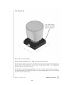
7.1.1 Describe the product's protective housing and how it serves to prevent unnecessary
human access to laser radiation.
The laser is mounted inside of a solid aluminum tube. The laser only fires forward.
Each laser tube is securely mounted inside a larger housing that prevents unnecessary
human access.
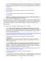
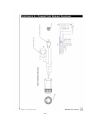
Is additional information attached? ( X )Yes ( )No See Figure 4.
FIGURE 4
- 22 -
7.1.2 Describe how the protective housing prevents access to unnecessary collateral
radiation.
The laser is mounted inside of a solid tube. Laser light has only one exit; therefore
collateral radiation is not possible.
Is additional information attached? ( )Yes ( X )No
7.2 Safety interlocks - Applicable for all laser products [1040.10(f)(2)(i)]
7.2.1 Provide a detailed mechanical diagram showing the location of each interlock
incorporated into the laser product for radiation safety.
Is a mechanical diagram attached? ( X )Yes ( )No
Describe each interlock and explain how each such interlock prevents access to laser
and/or collateral radiation when each portion of the protective housing is opened.
This product contains an electro-mechanical interlock. The interlock works on
centrifugal force and prevents the laser from firing when the Product is not rotating.
Is additional information attached? (
)Yes ( X )No
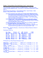
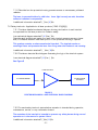
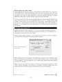
7.2.2 Provide an electrical block diagram illustrating the logic of the interlock system.
Is an electrical diagram attached? ( X )Yes (
)No
See Figure 5
COMPARATOR
LASER POWER
SUPPLIES
ACCELEROMETER
FIGURE 5
ELECTRO-MECHANICAL LASER INTERLOCK BLOCK DIAGRAM
7.2.3 For each safety interlock, state whether actuation is intended during operation,
maintenance, service, or any combination thereof.
The actuation of the interlock is intended to prevent any safety issues during normal
operation or in the event of a system failure.
Is additional information attached? ( )Yes ( X )No
- 23 -
7.2.4 For each safety interlock, state the highest level of laser radiation and collateral
radiation to which access is prevented.
In the event the product does not spin or does not properly pulse, the safety interlock
will prevent any collateral radiation.
7.3 Defeatable safety interlocks - Applicable to all laser products [1040.10(f)(2)(ii) and (iii)]
7.3.1 Identify which safety interlocks are designed to allow defeat and describe how they
operate.
The safety interlock can only be defeated when the product cover is removed. This
should only be done at by the manufacturer. Once removed, a jumper must be used to
short J34 pins 1 and 2 to allow the lasers to operate as if the unit was rotating.
Is additional description attached? (
)Yes ( X )No
7.3.2 For each safety interlock designed to allow defeat, state whether defeat is intended
during operation, maintenance, service, or any combination thereof.
The safety interlock is only intended during manufacture, service and maintenance. It
is not accessible to the user in the final Product.
7.3.3 For each safety interlock designed to allow defeat, describe how replacement of a
removed or displaced portion of the protective housing is not possible while the safety
interlocks are defeated.
Protective Housing is only replaced at the Manufacturer.
7.3.4 For each safety interlock designed to allow defeat, describe the means of providing
a visible or audible indication of defeat.
If the safety interlock is defeated, LED D15 will illuminate, indicating power is available
to the laser assemblies.
7.4 Safety interlock failure - Applicable to all required safety interlocks [1040.10(f)(2)(iii)] that
prevent access to Class IIIb or IV levels of laser radiation.
This product is a Class IM device
7.4.1 Describe how each safety interlock is "fail-safe," i.e., precludes removal or
displacement of the interlocked portion of the protective housing upon failure of the safety
interlock or is redundant
This product contains a single interlock mechanism which allows the laser power
supplies to turn on only when the Product is rotating at a sufficient speed. The typical
speed at which this circuit will turn on the laser power supplies is 360 revolutions per
minute. This accelerometer is located within the enclosure and is not accessible by
the user in the Product.
Are electrical/mechanical diagrams or additional information attached?
( X )Yes ( )No
See Figure 5.
7.4.2 Describe the possible modes of failure of each safety interlock and the resultant
effect upon the radiation safety of the laser product.
- 24 -
The accelerometer could provide a false high or low output reading.
If the false high failure were to occur, the Product will still rotate when power is
applied, but the lasers would turn on sooner than the design threshold in the spin up
cycle as the Product begins to rotate. As long as the Product rotates, the Product is
still Class 1M.
In the false low failure mode, the lasers will never turn on, even when the Product
rotates at full speed. So the product will not function, and it will not cause an
emission hazard
Is additional information attached? ( )Yes ( X )No
7.4.3 State the rating of each safety interlock, including the number of operational cycles
before failure.
The accelerometer is specified to operate from -120g to +120g. It is rated to
withstand a maximum acceleration of 4000 g’s. The Mean-Time-to-Failure for the
accelerometer is 1.4 * 109 hours.
7.5 Remote interlock connector - Applicable to Class IIIb or IV laser systems [1040.10(f)(3)]
Not Applicable
7.5.1 Describe the electrical and mechanical construction and operation of the remote
interlock connector. Give its circuit and physical location.
Not Applicable
Are electrical/mechanical diagrams or additional information attached? ( )Yes ( X)No
Not Applicable
7.5.2 Record the open-circuit electrical potential difference between the terminals
of the remote interlock connector.
____N/A______ Volts
Not Applicable
7.6 Key control - Required for Class IIIb or IV laser systems [1040.10(f)(4)]
Not Applicable
7.6.1 Describe the electrical and mechanical construction of the key-actuated master
control.
Not Applicable
Are electrical/mechanical diagrams or additional information attached? ( )Yes ( X )No
7.6.2 Describe the function of the key-actuated master control and how it renders the
laser inoperable when the key is removed.
Not Applicable
Are electrical/mechanical diagrams or additional information attached? ( )Yes ( X)No
- 25 -
7.6.3 Is the key removable in the "On" position?
Not Applicable
( )Yes ( )No N/A
7.7 Laser radiation emission indicator - Required for Class II, IIIa, IIIb, or IV laser systems
[1040.10(f)(5)]
Not Applicable
7.7.1 Describe in detail the mechanical and electrical characteristics of all emission
indicators installed pursuant to Section 1040.10(f)(5)(i) or (ii) and give their locations.
Note that if the energy source and remote controller(s) are separable by more than 2
meters, then each control must have an emission indicator.
Not Applicable
Are electrical/mechanical diagrams or additional information attached?
( )Yes ( X )No
7.7.2 Record the length of time each emission indicator of Class IIIb and IV laser systems
is actuated prior to the emission of accessible laser radiation.
Emission indicator delay: ______ sec
Not Applicable
7.8 Protective eyewear - Applicable to Class II, IIIa, IIIb or IV laser systems [1040.10(f)(5)(iv)]
State whether protective eyewear is supplied or recommended for use with the laser system. If
so, confirm that any visible emission indicator can be clearly seen through the protective
eyewear.
Not Applicable
Is protective eyewear supplied?
(
)Yes
( X )No
Not Applicable
Is it recommended?
( )Yes
( )No
Not Applicable
Can visible emission indicators be seen through eyewear?
(
)Yes
( )No
Not Applicable
7.9 Beam attenuator - Required for Class II, IIIa, IIIb or IV laser systems
[1040.10(f)(6)]
Not Applicable
- 26 -
7.9.1 For each beam attenuator, describe the mechanical and electrical characteristics
and how, when actuated, the attenuator prevents access by any part of the human body
to all laser and collateral radiation in excess of the accessible emission limits of Class I
and Table VI.
Not Applicable
Are electrical/mechanical diagrams or additional information attached?
( )Yes ( X )No
7.9.2 Describe the permanency of attachment of each beam attenuator.
Not Applicable
NOTE: You may apply for approval of alternate means of providing this protection if a
beam attenuator is inappropriate to the product.
7.10 Location of controls - Applicable to Class II, IIIa, IIIb or IV laser products [1040.10(f)(7)]
Explain how the location of each of the operation and adjustment controls of the laser product is
such that human exposure to laser or collateral radiation in excess of the accessible emission
limits of Class I and Table VI is prevented during operation or adjustment of such controls.
Not Applicable
7.11 Viewing optics - Applicable to all laser products [1040.10(f)(8)]
7.11.1 State whether all laser and collateral radiation accessible by virtue of viewing
optics, view ports, and display screens incorporated into the reported model of laser
product is less than the accessible emission limits of Class I and Table VI during operation
and maintenance. Include with your calculations pertinent attenuation factors, window
transmission characteristics, etc.
Yes, the emission limits are below that of Class I. The Product is not intended for use
with any viewing optics, so the Product is classified as Class IM.
Are electrical/mechanical diagrams or additional information attached?
( )Yes ( X )No
REMINDER: Report in Part 5 the location and identification of laser and collateral
radiation made accessible by viewing optics, viewports, and display screens. In Part 6,
report the highest levels.
7.11.2 Describe in detail, using diagrams or photographs and radiation transmission or
reflection spectra, each shutter or variable attenuator incorporated into viewing optics,
viewport, or display screen. Describe how exposure of the eye to laser or collateral
radiation in excess of the accessible emission limits of Class I and Table VI is prevented
whenever the shutter is opened or the attenuator is varied.
N/A. This Product does not have a shutter and does not have an attenuator. The
product does not have collateral radiation.
Are diagrams/photographs or additional information attached?
( )Yes ( X )No N/A
7.11.3 Describe how exposure of the eye to laser or collateral radiation in excess of the
accessible emission limits of Class I and Table VI is prevented in the event of failure of the
shutter or variable attenuator, as required by Section 1040.10(f)(8)(ii).
- 27 -
N/A. This product does not have a shutter and does not have an attenuator. This
product does not have collateral radiation.
Are diagrams or additional information attached?
( )Yes ( X )No
7.12 Scanning safeguard - Required for certain laser products with scanned laser radiation
[1040.10(f)(9)].
Describe the mechanical, electrical, and functional characteristics of any required scan failure
safeguard. Include calculations to show that the safeguard's reaction time is adequate for
compliance with this section.
The scanning safeguard consists of a centrifugal switch.
In the event of a system failure, the spin down time of the laser assembly is approximately
10 seconds. The centrifugal switch has a reaction time of 10 milliseconds therefore this
centrifugal switch has a superior response time.
Are electrical/mechanical diagrams, calculations, or additional information attached?
( )Yes ( X )No
NOTE: A safeguard is required when scan failure would cause the product to exceed the
emission limits of the class of the product, or in the case of Class IIIb or IV laser products
would cause the accessible emission limits of Class IIIa to be exceeded.
7.13 Manual reset - Applicable to Class IV laser systems manufactured after August 20, 1986.
Provide the circuit and physical description and location of the means provided to require manual
restart following interruption of emission caused by power failure of at least 5 seconds or
deactivation through the remote interlock connector.
Not Applicable
7.14 Medical laser product - Applicable to Class III or IV medical laser products intended for invivo surgical, therapeutic, or diagnostic irradiation of the human body.
NOTE: The requirement in section 1040.11(a) does not apply to visible aiming beams less
than the accessible emission limits of Class IIIa except for ophthalmic indications.
If your product is a Class III or IV medical laser product, provide the following information:
7.14.1 Describe the means incorporated into the product to measure the level of laser
radiation intended for irradiating the human body; include circuit diagrams and/or optical
system diagrams.
Not Applicable
Are electrical/mechanical diagrams, calculations, or additional information attached?
( )Yes ( )No
Not Applicable
7.14.2 Specify the uncertainty in the measurement system and describe the method by
which it was derived.
Not Applicable
- 28 -
Are calculations or additional information attached?
( )Yes ( )No
Not Applicable
7.14.3 Is the displayed power/energy level measured at the point of delivery or earlier
and then calculated? If the displayed level is calculated incorporating system constants,
losses, attenuation factors, etc. please provide calculations to demonstrate accurate
calibration of the delivered beam to within + or - 20%, as required by 1040.11(a)(1).
Not Applicable
Are calculations or additional information attached?
( )Yes ( )No
Not Applicable
7.14.4 Are procedures and a schedule for recalibration of the measurement system
included in the user instructions?
Not Applicable
( )Yes ( )No
If yes, please identify location in the user instructions:
7.15 Surveying, leveling, or alignment laser products - Is the product a surveying, leveling, or
alignment laser product?
( )Yes
( X )No
If yes, then it is subject to the requirements of section 1040.11(b). If the product's class
exceeds Class IIIa then an approved variance from the performance requirements in this section
would be necessary prior to introduction into commerce. Procedures for applying for a variance
are given in section 1010.4, and described in the Compliance Guide, page 13.
7.16 Demonstration laser products - Is the product a demonstration laser product?
( )Yes
( X )No
If yes, then it is subject to the requirements of section 1040.11(c). If the product's class
exceeds Class IIIa then an approved variance from the performance requirements in this section
would be necessary prior to introduction into commerce. Procedures for applying for a variance
are given in the Compliance Guide, pages 13 and 16-22.
An Application for a Variance from 21 CFR 1040.11(c) for a Laser Light Show, Display, or
Device (form FDA 3147) must be submitted, following the instructions on the form. A Laser Light
Show report may also be required if you intend to produce shows or displays with Class IIIb or
Class IV demonstration laser products. The Reporting Guide for Laser Light Shows and Displays
should be filled out and submitted along with this report and the variance application, following
the instructions in each document.
Not Applicable
7.16.1 Is a Variance application being submitted along with this report?
( )Yes - date of submission: _________ ( )No
Not Applicable
- 29 -
7.16.2 Is a Laser Light Show report being submitted along with this report?
( )Yes - date of submission: _________ ( )No
Not Applicable
PART 8: QUALITY CONTROL TESTS AND TESTING PROCEDURES
8.1 Attach, and identify as attachments to Part 8, samples of documents that describe, specify,
or relate to procedures or tests used to ensure compliance of your reported product with the
standard, including compliance with all performance, labeling, and informational requirements.
These may include:
( X ) specification controls for critical components,
( ) manufacturing and assembly control procedures,
( ) inspection and test control procedures,
( ) assembly and test traveler forms,
( X ) inspection and test reports and checklists, and/or
( ) other(s) ___________________________________________
(specify)
See Appenidx B for Laser Diode Specification (critical component)
See Appendiz C for Inspection Check List
8.2 If formal quality control and testing procedures have not been implemented or are not
sufficient to assure that your product(s) will comply with the standard, explain how you assure
that your products comply and submit supporting documentation.
NOTE: Section 1010.2(c) requires that certification be based on a test, in accordance with
the standard, of each unit or on a program in accordance with good manufacturing
practices. Failure to maintain an adequate testing program may result in disapproval of the
program by CDRH.
- 30 -
PART 9: LIFE AND ENDURANCE TESTING
Describe those tests and controls used to ensure that the reported product will remain in
compliance with the Federal laser product performance standard during its useful life. Items to
be addressed include:
9.1 Dimensional stability and rigidity of mechanical parts and assemblies such as housings and
mounts
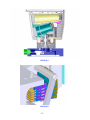
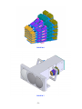
There should be no deviation in the operation of the final Product of the housing or
mechanical assemblies. Figures 6.1 thru 6.7 show the housing and internal assemblies.
FIGURE 6.1
- 31 -
FIGURE 6.2
FIGURE 6.3
- 32 -
FIGURE 6.4
FIGURE 6.5
- 33 -
FIGURE 6.6
FIGURE 6.7
- 34 -
Is additional information/documentation attached?
( )Yes ( )No
9.2 Design and ratings of electrical and electronic components
Laser Datasheet attached as Appendix A
Is additional information/documentation attached?
( X )Yes ( )No
9.3 Environmental stability of components such as filter materials, coatings, and
adhesives
Not applicable.
Is additional information/documentation attached?
( )Yes ( X )No
9.4 Design and testing of features designed to meet Federal laser product
performance requirements
Is additional information/documentation attached?
( )Yes ( X )No
9.5 Other factors that might affect your product's radiation safety
Not applicable
Is additional information/documentation attached?
( )Yes ( )No
NOTE: Maintenance and/or service instructions must include schedules for
maintenance and replacement of those components related to the compliance
of the product that may be expected to be replenished or replaced during the
life of the product.
- 35 -
PART 10: INSTRUMENTATION AND CALIBRATION
Describe those tests and controls used to ensure that the reported product will
remain in compliance with the Federal laser product performance standard during
its useful life. Items to be addressed include:
10.1 List the instruments you use to determine compliance of the reported
product with the standard. Describe these instruments or provide copies of
specification sheets. Identify each detector's aperture size, if applicable.
Not applicable. However, a Sony CCD-TRV28 infrared vision camera was used
to verify the calculations that were performed earlier in this report. The
camera provided the laser image pattern and it was used to determine the
point of maximum intensity and thus verify the calculations.
Is additional information attached? ( )Yes ( X )No
10.2 Indicate how the measurement system collects or accounts for the total
radiant energy or power specified in Section 1040.10(e).
Not Applicable
Is additional information attached? ( )Yes ( X )No
10.3 Provide a measurement error analysis (for all sources of error identified) and
an uncertainty statement for all measurement data reported.
Not Applicable
Is additional information attached? ( )Yes ( )No
NOTE: If it is clear from the measurement data, including the total estimated
uncertainty, that the levels are well below the applicable class limit, then an
error analysis and uncertainty statement are not required. For, example, an
error analysis and uncertainty statement would not be required for a 1.5 milli
watt HeNe laser product classified in Class IIIa.
10.4 Provide instrument calibration schedules and indicate how your instruments
are calibrated (e.g., calibrated by your company against a working standard,
returned to the manufacturer of the instrument, sent to an independent
calibration laboratory).
Not Applicable
Is additional information attached? ( )Yes ( )No
NOTE: If your laser product operates at a level closely approaching a specified
limit, high accuracy and traceability to the National Institute of Standards and
Technology (previously known as the National Bureau of Standards) are
important.
- 36 -
APPENDEX A – HDL 64E USER’S MANUAL
- 37 -
- 38 -
- 39 -
- 40 -
- 41 -
- 42 -
- 43 -
- 44 -
- 45 -
- 46 -
- 47 -
- 48 -
- 49 -
- 50 -
- 51 -
- 52 -
- 53 -
- 54 -
- 55 -
APPENDIX B – MANUFACTURER’S LASER DIODE SPECIFICATION
- 56 -
- 57 -
- 58 -
- 59 -
- 60 -
- 61 -
APPENDIX C – INSPECTION CHECK LIST
Title:
Form, Checklist, WIP, HDL
Model #: 80-HDL64E
W/O#: ________________
Doc P/N:
70-0008
Rev:
E3
Date:_____________
S/N#: ________________
Items:
Serial #:
Upper Detector PCB
______________________
Lower Detector PCB
______________________
UL Laser Assembly
______________________
UR Laser Assembly
______________________
LL Laser Assembly
______________________
LR Laser Assembly
______________________
Upper Block Assembly
______________________
Lower Block Assembly
______________________
DSP PCB
______________________
Motor Assembly
______________________
Outside Shell Assembly
______________________
Change History:
Revision
Description of change
Effective
Change by
E1
Initial Release.
2/12/07
S.Ng
E2
Checklist Updated. Add Task# 240.
3/8/07
S.Ng
E3
Added additional lockdown checks and pack& ship
checks.
3/19/07
S.Ng
- 62 -
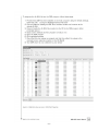
Task# 230 Document Preparation:
Task#
230
Descriptions
By
Date
Verify
By
Date
Verify
By
Date
Verify
Verify the following checklists attached with this
document.
_ Checklist 66-0005 (Upper Detector PCB Alignment)
_ Checklist 66-0005 (Lower Detector PCB Alignment)
230.1
_ Checklist 66-0006 (Upper Block Laser Alignment)
_ Checklist 66-0007 (Lower Block Laser Alignment)
_ Checklist 66-0002 (Motor Assembly)
_ Checklist 66-0003 (DSP Board)
230.2
Verify all S/N’s (except Outer Shell Assy.) are filled in
on Page 1 of this document.
Task# 240 Wiring:
Task#
240
240.1
Descriptions
Verify all the laser cables are connected properly
according to the color code diagram P/N: 70-0009.
Verify the Upper and Lower Block Flat Flex Cables
230.2 are copper shielded and connected properly onto
the boards.
Task# 400 Check for 64 Lasers (1st Time):
Task#
400
Descriptions
400.1 Verify all 32 Lasers on upper board are firing.
400.2 Verify all 32 Lasers on lower board are firing.
- 63 -
Task# 450 Preliminary Balance
Task#
450
Descriptions
By
Date
Verify
By
Date
Verify
By
Date
Verify
Verify the unit without the shell is balanced.
Reading from Oscilloscope:
450.1
Channel 1: ____________mV
(9.0 mV max)
Channel 2: ____________mV
(9.0 mV max)
Task# 480 1st Images Check
Task#
480
Descriptions
480.1 Bring the Unit outside and check for Images
Task# 500 Balance with Shell
Task#
500
Descriptions
Verify the unit with shell is balanced with additional
weight on the outside of the shell.
500.1 Reading from Oscilloscope:
Channel 1: ____________mV
(6.0 mV max)
Channel 2: ____________mV
(6.0 mV max)
Verify the unit with shell is balanced with additional
weight on the inside of the shell.
500.2
Reading from Oscilloscope:
Channel 1: ____________mV
(7.0 mV max)
Channel 2: ____________mV
(7.0 mV max)
- 64 -
Task# 520 Check for 64 Lasers (2nd Time):
Task#
520
Descriptions
By
Date
Verify
By
Date
Verify
520.1 Verify all 32 Lasers on upper board are firing.
520.2 Verify all 32 Lasers on lower board are firing.
Task# 550 Hardware Lock Down
Task#
550
Descriptions
550.1
Apply Loctite 242 (Blue) to all setscrews on the
moveable counter weights on the round rods.
550.2
Apply Loctite 242 (Blue) to the both 10-32 screws on
the round counter weights on the upper block.
550.3 Verify all screws inside the unit are tightened.
550.4 Verify all cables inside the unit are security tied down.
550.5 Verify all lens are clean and without any scratches.
550.6 Verify the window on the shell is clean.
550.7 Remove Jumper J34 on DSP board.
550.8
Verify all S/N’s on Page 1 of Checklist 66-0001 is
filled.
550.9
Install O-Ring (P/N: 48-116) on the bottom of the Shell
Mount Base Plate.
550.9
Install the shell and apply Loctite 242 (Blue) to Shell
screws with lock washers.
550.10
Flip the unit upside down. Verify there is no loose
object inside the unit.
550.11 Install the Square Base Assembly to the unit.
- 65 -
550.13
Verify the use of the following hardware to mount the
Rotary Coupling Connector Assy. (P/N: 82-507) to the
bottom of the motor spindle:
Qty 3: 4-40 x 3/8” Soc Cap screws P/N: 40-043SHCS
With Loctite 242 (Blue)
Qty 3: #4 Lock washer. P/N:43-04SL
Qty 3: #4 Flat washer (Special) P/N: 43-04
Task# 570 Check for 64 Lasers (3rd Time):
Task#
570
Descriptions
By
Date
Verify
By
Date
Verify
By
Date
Verify
570.1 Verify all 32 Lasers on upper board are firing.
570.2 Verify all 32 Lasers on lower board are firing.
590 Images Check (2nd Time)
Task#
590
Descriptions
590.1 Install the bottom square cover with O-ring.
590.2 Bring the Unit outside and check for Images.
Task# 600 Burn-In
Task#
600
Descriptions
Record Start Time and End Time
Start Date : ___________ Time: _____________
600.1 End Date: ____________ Time: _____________
Total Burn-In Time: ____________________hrs
- 66 -
Task# 800 Final Images Check
Task#
800
Descriptions
By
Date
Verify
By
Date
Verify
800.1 Install the bottom square cover with O-ring.
800.2 Bring the unit outside and check for images.
Task# 990 Pack and Ship
Task#
990
Descriptions
Verify Velodyne S/N label installed on the bottom of
the unit.
990.2 Tool Kit P/N: 92-0090
990.1
Verify all the item are inside the tool pouch:
Qty:1 ___ Tool Pouch P/N: 92-0101
______________________________
Hex Allen Wrench Drivers:
Qty:1 ___ 050” Hex Allen Wrench P/N: 92-0091
Qty:1 ___ 1/16” Hex Allen Wrench P/N: 92-0092
Qty:1 ___3/32” Hex Allen Wrench P/N: 92-0095
Qty:1 ___ 5/64” Hex Allen Wrench P/N: 92-0097
Hex Allen Wrench/T Handle:
Qty:1 ___3/16” Hex Allen Wrench w/T-Handle
P/N: 92-0093
Qty:1 ___3/32” Hex Allen Wrench w/T-Handle
P/N: 92-0094
Qty:1 ___7/64” Hex Allen Wrench w/T-Handle
P/N: 92-0098
Qty:1 ___9/64” Hex Allen Wrench w/T-Handle
P/N: 92-0099
Qty:1 ___5/32” Hex Allen Wrench w/T-Handle
P/N: 92-0096
Hex Socket Wrench:
Qty:1 ___7/64” Hex Socket Wrench
Tweezer:
Qty:1 ___Tweezer, #2A Taper Round Blunt 4 _” Lg
SS P/N: 92-0101
- 67 -
Qty:1 ___Lens Cleaning Paper Sheets Pack
P/N: 92-0102
Labels:
Qty:1 ___ Label, Class 1 M Laser Warning
Verify Model #, Serial # and Mfg Date are written on
the label using the black permanent marker pan.
P/N:63-131
Qty:4 ___ Label, Warning, Triangle P/N: 63-132
990.3
Verify tool kit pouch and connection cables are put
inside the crate.
990.4 Verify this Checklist is completed.
- 68 -
Rework History (1st Page)
Date
Reject Description
Rejected
By
Comments
Date
Failure Analysis
Performed
By
Comments
Date
Description of Rework
Reworked
By
Comments
Date
Reject Description
Rejected
By
Comments
Date
Failure Analysis
Performed
By
Comments
Date
Description of Rework
Reworked
By
Comments
- 69 -
Rework History (2nd Pages)
Date
Reject Description
Rejected
By
Comments
Date
Failure Analysis
Performed
By
Comments
Date
Description of Rework
Reworked
By
Comments
Date
Reject Description
Rejected
By
Comments
Date
Failure Analysis
Performed
By
Comments
Date
Description of Rework
Reworked
By
Comments
- 70 -
Velodyne Acoustics, Inc.
345 Digital Drive
Morgan Hill, CA 95037
408.465.2800 voice
408.779.9227 fax
408.779.9208 service fax
www.velodyne.com
Service E-mail: [email protected]
Product E-mail: [email protected]
Technical E-mail: [email protected]
Sales E-mail: [email protected]
63-300 Rev C NOV07
Other trademarks or registered trademarks are property
of their respective owners.