1
July 2001
4502
TT-2D USERS MANUAL
1.
2.
3.
4.
5.
6.
7.
8.
9.
INTRODUCTION
CONTROL FUNCTIONS
GETTING STARTED
HOW IT WORKS
CALIBRATION
BATTERY TEST
SPECIFICATIONS
WARRANTY AND REPAIR INFORMATION
COMMONLY ASKED QUESTIONS
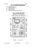
Resonance
indicator LEDº
Button A
º
Button B
º
» Transducer
connection
» LCD display
Power/fine
frequency º
» Coarse
frequency set
Figure 1
TT-2 User Manual
Control Location
EDI P/N 700-013
Page 1
1
INTRODUCTION
The TT-2D is designed to test acoustic transducers for resonance over the frequency
range of 500 Hz to 500 KHz. The TT-2D tests all types of transducers, including
transformer-coupled and magnetostrictive devices. The load characteristic (capacitive,
resistive, or inductive) and impedance at resonance are displayed on the two line LCD
display. The leakage resistance of the transducer can be measured and displayed
over the range of 10 ohms to 5 megohms.
2
CONTROL FUNCTIONS
Refer to figure 1 for the location of the controls discussed in this section.
2.01
TRANSDUCER CONNECTION
The transducer output connects to the transducer under test. WARNING, do
not connect a source of power to this connector. If you do, the TT-2D will
be seriously damaged. This is an output only.
2.02
LCD DISPLAY
Normally displays the frequency on the lower line and the impedance and
relative phase on the upper line. Battery voltage and software version are
displayed for 3 seconds when the power is turned on.
2.03
COARSE FREQUENCY SET KNOB
This controls the frequency sent to the transducer from less than 500 Hz to over
500 KHz.
2.04
POWER/FINE FREQUENCY SWITCH
This knob controls the power and is also used to fine tune the frequency setting.
The frequency range is about 10% of that set by the coarse frequency control.
2.05
BUTTON A
The main function of this push button switch is to select the resistance
measuring mode. When this button is pressed, the DC resistance of the
transducer is displayed in ohms on the bottom line of the display. The range
covers 10 ohms to 5 megohms. Press button ‘B’ once to return to normal
operation.
2.05.01
During power-up, press button ‘A’ to increase the display contrast.
BUTTON B
The main function of this push button switch is to select one of the three
frequency ranges. The range increments each time this button is pressed. Each
range covers a decade as shown below:
2.06.00.01
Range 1:
500 Hz to 5 KHz.
2.06.00.02
Range 2:
5 KHz to 50 KHz.
2.06.00.03
Range 3:
50 KHz to 500 KHz.
2.06.01
During power-up, press button ‘B’ to decrease the display contrast.
2.06
TT-2 User Manual
EDI P/N 700-013
Page 2
2.06.02
2.07
To make a selected frequency range as the default range, select
the range and before releasing button ‘B’, press button ‘A’.
Release both buttons when the display shows ‘FR store’ on the
bottom line. This range will be selected each time the TT-2D is
powered-up.
RESONANCE INDICATOR
This LED brightens when the frequency approaches the resonant point of the
transducer. The brighter the LED, the lower the impedance is. The LED also
flashes on power-up while the TT-2D initiates the self-test routine.
3
GETTING STARTED
Connect the TT-2D XDUCER output to a transducer. Turn the power on and the TT-2D
will go through a self-test routine while displaying the battery voltage. While the TT-2D
is in the self-test mode, the contrast may be set and stored by pressing buttons ‘A’ or
‘B’. After the TT-2D displays the frequency on the bottom line, select the appropriate
frequency range by pressing button B. Rotate the coarse frequency control while
watching the resonance indicator LED for resonant points. There will be three
resonance points for most transducers. Choose the one that has the brightest
indication on the LED. Fine tune the frequency with the fine frequency control while
watching the display for the lowest Zo indication. The phase indication will usually be
near zero when the impedance is at a minimum.
3.01
SORTING OUT MULTIPLE RESONANCE POINTS
Most all transducers you test will have three major resonance points. A major
resonance point has a significant peak in the resonance indicator and a low
impedance over a narrow frequency range. The problem is to determine the
correct resonant point. This will usually be the frequency where the most power
is transferred from the face of the transducer. Check the energy transfer at each
resonant point by pressing on the exact center of the transducer face with a
fingertip while observing the impedance displayed on the top line of the LCD.
The readings will change noticeably with moderate finger pressure. The
resonant point that produces the most pronounced change of impedance is
usually, BUT NOT ALWAYS, the correct operating frequency for the transducer.
3.02
MEASURING TRANSDUCER IMPEDANCE
The transducer impedance at resonance is indicated on the upper left of the
LCD. The relative phase angle is displayed in the upper right of the LCD. A
negative (-) sign indicates the load looks capacitive to the TT-2D, and a
TT-2 User Manual
EDI P/N 700-013
Page 3
positive sign (+) indicates the load is inductive. The lowest impedance reading will
usually occur when the relative phase angle displayed is less than ten.
3.03
TRANSDUCER DC RESISTANCE
Press button ‘A’ to check the resistance of the transducer. The measurement
range is from 10 ohms to 5 megohms. Piezoelectric transducers that are not
transformer coupled should indicate “> 5 Megs” of leakage after a few seconds.
Transformer coupled transducers usually have only a few ohms of resistance,
and the LCD will indicate “<10 Ohms.”
4
HOW IT WORKS
The TT-2D sends a signal through a 100 ohm resistor to the transducer under test.
The voltage waveform at the transducer is sampled at three specific points per cycle.
The relationship of the voltages at the sample points determine the impedance and
relative phase of the voltage across the transducer. The impedance is calculated and
displayed over the range of 1 to 9990 ohms and the relative phase shift is displayed to
the right of the impedance reading. A plus (+) sign (voltage leads current) indicates an
inductive load, and a minus (-) sign (voltage lags current) indicates a capacitive load.
The numbers following the polarity sign range from 0 to 30, with the higher numbers
indicating a higher reactance.
5
CALIBRATION
Calibration of the TT-2D should not be necessary unless repairs have been made or
internal parts have been changed. The calibration is done with the output shortcircuited. The TT-2D is then checked with a 100 ohm and 1000 ohm resistor across
the output to see if the displayed readings are within specifications. The equipment
required to check the TT-2D calibration follows:
5.00.01
Frequency counter with .005% or better accuracy.
5.00.02
100 ohm 5% resistor.
5.00.03
1000 ohm 5% resistor.
5.01
CHECKING SHORT CIRCUIT LOAD CALIBRATION
Turn the TT-2D on. Check the displayed battery voltage. It must be greater
than 6.5 volts. If not, replace the battery. Set the frequency to 50 KHz and short
the output by connecting the test cable clip-leads together. The impedance
should read within +1 to -1. If the reading is not within this range the unit should
be calibrated. See the SHORT CIRCUIT LOAD CALIBRATION procedure below
for instructions.
5.02
CHECKING RESISTIVE LOAD CALIBRATION
Turn the TT-2D on and set the frequency to 50 KHz. Short the clip leads and
verify that the reading is within +/- 1 ohm. If the reading is out of spec, try the
SHORT CIRCUIT CALIBRATION procedure.
TT-2 User Manual
EDI P/N 700-013
Page 4
5.02.01
5.02.02
Connect the 100 ohm resistor to the clip leads and verify the
displayed reading is 100 +/- 10 ohms. If the reading is not
within specifications the unit must be returned to the factory
for repair.
Remove the 100 ohm resistor and connect the 1000 ohm
resistor. Verify that the displayed reading is 1000 +/- 100
ohms. If the reading is not within specifications the unit
must be returned to the factory for repair.
5.03
CHECKING FREQUENCY ACCURACY
Set the TT-2D as close as possible to 50 KHz. Connect the counter to the
XDUCER jack and verify that the displayed reading is within 0.05% (+/- 0.025
kHz at 50 Khz) of that on the frequency counter. If the reading is out of spec the
unit must be returned to the factory for repair.
5.04
SHORT CIRCUIT LOAD CALIBRATION
Turn the TT-2D on and store frequency range 3 as the default. Set the
frequency to 50 Khz. Turn TT-2D off. Connect the clip leads together to short
circuit the output. Press and hold both the ‘A’ and ‘B’ buttons and then turn on
the power. Watch the display and release both buttons immediately after the
display shows ‘Cal mode’. If the buttons are not released quickly, the unit will
not enter the calibration mode. Wait a few seconds after the display changes to
“ADC=xxx” on the top line and then press button ‘B’ to store the ADC calibration
value. Turn the TT-2D off then back on. Check to make sure the impedance
reads within +/- 1 ohm. If not, check the test lead for continuity and repeat the
calibration. If the reading is still out of specification the unit must be returned to
the factory for repair.
5.05
OHM METER CHECK
Turn the TT-2D on and press button “A” to put the TT-2D into the DC resistance
measurement mode. Short the clip leads together and verity that the display reads <
10 Ohms. Open the clip leads and verify the display reads > 5 M ohms. Place a 10 K
resistor across the clip leads and verify the display reading is between 9000 and 11000
ohms. If the readings are out of specification the unit must be returned to the factory
for repair.
6
BATTERY TEST
The battery should be replaced if the voltage falls below 6.5 volts as indicated on the
display when the TT-2D is powered-up.
6.01
BATTERY REPLACEMENT
The battery compartment is located on the back side of the TT-2D. Turn the TT2D face down and remove the battery cover by pressing down and outward with
your thumb. The cover will then slide free from the case, exposing the battery.
If possible, use 9V alkaline batteries for replacement.
TT-2 User Manual
EDI P/N 700-013
Page 5
7
SPECIFICATIONS
FREQUENCY RANGE:
FREQUENCY ACCURACY:
FREQUENCY RESOLUTION:
IMPEDANCE RANGE:
IMPEDANCE ACCURACY:
TRANSDUCER TYPES:
BATTERY TYPE:
CURRENT DRAIN:
EST BATTERY LIFE:
RECOMMENDED BATTERY:
WEIGHT:
SHIPPING WEIGHT:
.5 to 500 KHz, typically .1 to 550 KHZ.
0.05% of indicated frequency +/- 1 digit.
0.01 KHz
5 - 1000 ohm, usable 1 - 9990 ohms.
10% of indicated reading.
All types, including transformer coupled.
Standard 9V transistor radio type.
20 mA avg, 60 mA max.
6 to 8 hours continuous use.
Alkaline type similar to EVER READY #522
or equivalent.
11 ounces with battery and test cable.
2 pounds.
8
WARRANTY INFORMATION
Unit will be repaired free of charge for one year from date of purchase providing there is
no water damage or other evidence of improper use or handling. Purchaser must ship
unit prepaid to address below; EDI will pay the return freight. Please call before
shipping your unit back to us.
Phone:
1-757-421-2968
Fax:
1-757-421-0518
For repair ship to:
Electronic Devices, Inc.
3140 Bunch Walnuts Road
Chesapeake, VA. 23322
ATTN: Service Department
Please enclose a note describing the problem.
9
COMMONLY ASKED QUESTIONS
9.01
HOW TO SET THE CONTRAST
To set the contrast, turn the TT-2D off and back on. Press button ‘A’ or ‘B’ while
the battery voltage is displayed. The contrast setting is stored when the
impedance and frequency display appears approximately three seconds after
releasing the buttons.
TT-2 User Manual
EDI P/N 700-013
Page 6
9.02
HOW TO CHANGE THE FREQUENCY RANGE
To change the frequency range press button ‘B’. The range (1, 2, or 3) will be
displayed while the button is held down. When the button is released the TT-2D
will operate on that range.
9.02.01
The frequency range can be stored so it is selected whenever the
TT-2D is turned on. To store the range select it as above, but do
not release button ‘B’ when the range number is displayed. While
the range number is displayed, press button ‘A’ then release both
buttons. The display will momentarily read “FR store” to indicate
the frequency range has been stored to memory.
9.03
HOW TO MEASURE LEAKAGE
Press and release button ‘A’ and the display will read “Ohms chk” on the top
line. The resistance will be displayed on the bottom line in exponential format.
For example, a 1,200 ohm resistor will read “1.20E+03" on the bottom line of the
display. If no leakage is present, the display will read “>5M ohms”. Allow
several seconds to elapse for the reading to stabilize. To return to normal
operation, press and release button ‘B’.
9.04
HOW TO DETERMINE IF A TRANSDUCER IS DEFECTIVE
A transducer is defective or the wiring is faulty if no resonant points are
observed. All transducers should have a strong indication of resonance at or
near the published operating frequency.
9.04.01
A multi-element transducer with one damaged element may
resonate at the correct frequency, but the impedance reading will
change by a good amount. If there is any doubt, compare the
readings to a known good transducer. When making comparative
readings, both transducers must be tested in air or in water. Do
not compare the reading in air to the reading in water as there will
be a big difference in the measured impedance.
9.04.02
If a transducer indicates any measurable leakage (less than 5M
ohms), the wiring should be checked. If the wiring is not leaky, the
transducer should be replaced even if it is working ok on the depth
sounder. Becuase of the high pulse voltage used, a leaky
transducer will soon break down internally and cease to operate.
TT-2 User Manual
EDI P/N 700-013
Page 7