1
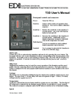
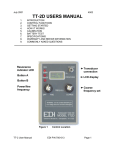
June 1998
8299
TT-2 USERS MANUAL
1.0
2.0
3.0
4.0
5.0
6.0
INTRODUCTION
CONTROL FUNCTIONS
GETTING STARTED
HOW IT WORKS
SPECIFICATIONS
WARRANTY AND REPAIR INFORMATION.
Figure 1
TT-2 User Manual.
Control Location
EDI P/N 700-010
Page 1
1.0
INTRODUCTION
The TT-2 is designed to test acoustic transducers for resonance over the frequency
range of 500 Hz to 500 KHz. The TT-2 tests all types of transducers, including
transformer-coupled and magnetostrictive devices. The load characteristic (capacitive,
resistive, or inductive) is indicated by a dual color LED. Leakage current and continuity
are monitored by another dual-color LED. A meter displays the relative current
through the transducer over a large dynamic range. Outputs are provided for
connection to the transducer under test and a frequency counter.
2.0
CONTROL FUNCTIONS
Refer to figure 1 for the location of the controls discussed in this section.
2.1
METER
The meter indicates the relative amount of current passed through the transducer. The
higher the reading, the more current through the load. The meter will peak at series
resonance, and dip at parallel resonance. There is a prominent mark on the meter
scale labeled “Zo”. This Zo marker reference is used with the ZOUT knob to
determine the transducer impedance at resonance.
2.2
COUNTER OUTPUT
The counter output provides a 5V p-p square-wave with a source impedance of 10 K
ohms, and is used when accurate frequency measurements are required. WARNING,
do not connect a source of power to this connector. If you do, the TT-2 will be
damaged. This is an output only.
2.3
TRANSDUCER OUTPUT
The transducer output connects to the transducer under test. WARNING, do not
connect a source of power to this connector. If you do, the TT-2 will be seriously
damaged. This is an output only.
2.4
OUTPUT IMPEDANCE CONTROL
This control governs the resistance between the TT-2's signal generator and the
transducer. It is normally set in the upper ranges for high impedance transducers and
lower ranges for transformer coupled units. At resonance, the impedance of the
transducer is read by adjusting the ZOUT control so the meter is on the Zo mark. The
impedance in ohms is the setting of the ZOUT dial times one hundred.
2.5
FREQUENCY CONTROL
This control sets the operating frequency of the TT-2's oscillator. Multiply the reading
by the selected range to read the frequency in KHZ. For example, if the frequency knob
reads 20 and the POWER/RANGE switch is set to the X10 position, the output
frequency will be 20 times 10, or 200 KHz.
TT-2 User Manual.
EDI P/N 700-010
Page 2
2.6
POWER/RANGE SWITCH
This switch turns the power on and selects the frequency decade multiplier for the
FREQUENCY CONTROL. Power off is at the maximum CCW position. The first
position to the right (X10) covers 50 to 550 KHz. The next position, (X1) covers 5 to
55 KHz, and the maximum CW position (X.1) covers 500 Hz to 5.5 KHz.
2.7
RESONANCE LED
This dual-color LED tells if the transducer presents a capacitive or inductive load to the
TT-2. If the indicator is red, the transducer is capacitive. If green, then the transducer
is inductive. At resonance this indicator is dim or extinguished.
2.8
LEAKAGE LED
This dual-color LED indicates the amount of dc resistance (or leakage) through the
transducer. For resistances above 3 megohms, the indicator is off. At less than 3
megohms, the indicator is red. Below 10K ohms, the indicator is both red and green,
appearing orange. The red section of this led flashes briefly when the power is turned
on, indicating that the battery is good. If the XDUCER output is shorted, this LED may
take 70 - 80 seconds to extinguish after the short is removed. Because of the long time
required for the leakage indicator to respond, always leave the TT-2 connected to the
transducer for about two minutes to make sure any leakage currents will show up.
3.0
GETTING STARTED
Connect the TT-2 XDUCER output to a transducer. Turn the power on and select the
appropriate frequency range. Set the Z OUT knob to the mid-range position. Rotate
the frequency control while watching the meter for the highest peak. The
RESONANCE indicator will usually be red below resonance, and will rapidly change to
green just above resonance. There will be three resonance points for most
transducers. Adjust the Z OUT control so the meter falls across the Zo mark to get the
most accurate and repeatable frequency reading. If it is not possible to set the meter to
the Zo mark, adjust the ZOUT knob to get as close as possible to the Zo reference
mark on the meter.
3.1
SORTING OUT MULTIPLE RESONANCE POINTS
Most all transducers you test will have three major resonance points. A major
resonance point has a significant peak in the current meter along with a quick change
in the color of the RESONANCE light. The problem is to determine the correct resonant
point. This will usually be the frequency where the most power is transferred from the
face of the transducer. Check the energy transfer at each resonant frequency by
pressing the palm of your hand on the transducer face while observing the TT-2's
meter. The meter will dip noticeably with moderate hand pressure at the one of the
resonant frequencies. This point is usually, BUT NOT ALWAYS, the correct operating
frequency for the transducer. The TT-2's meter is usually more sensitive to transducer
loading when the transducer presents a slightly capacitive load. Setting the frequency
so the red RESONANCE light is barely visible will cause the largest dip of the meter
when the transducer face is pressed. Often, a light touch of a finger tip at the exact
TT-2 User Manual.
EDI P/N 700-010
Page 3
center of the transducer face will cause a dip of the meter at one frequency only.
Again, this is usually, but not always, the correct operating frequency for the
transducer.
3.2
MEASURING TRANSDUCER IMPEDANCE
An approximate indication of the magnitude of the transducer impedance at resonance
can be obtained by adjusting the Z OUT control so the meter lays over the Zo mark,
located on the meter scale. Read the scale surrounding the Z OUT control and multiply
it by one hundred to get the transducer impedance. Some transducers may prevent the
meter from reaching the Zo mark. In this case, remove the transducer and place a
potentiometer across the XDUCER output of the TT-2. Adjust this external
potentiometer till the meter reads the same value it had with the transducer connected
to the TT-2. Remove the potentiometer and read the resistance with an ohmmeter. It
will be close to that of the transducer impedance at resonance. Note that the
transducer must be at resonance for the above tests to have any meaning. Resonance
is indicated when the LOAD indicator is dim or out, and the current is at a peak.
3.3
TRANSDUCER DC RESISTANCE
The approximate DC resistance of the transducer under test is indicated by the
XDUCER indicator. If the resistance is less than 3 megohms, the XDUCER indicator
will stay red, indicating leakage in the transducer. If the resistance is less than 10 Kilo
ohms, the XDUCER indicator will show will light both the red and green LEDS. This
condition indicates either a short or a transformer coupled transducer. Transformer
coupled transducers usually have only a few ohms of resistance. If the TT-2 is
connected to a short circuit or transformer coupled transducer, the 3 megohm (red)
XDUCER light will require about 75 seconds before it goes out after removal of the
short. It is best to turn the TT-2 on and wait for the XDUCER light to go out before
connecting it to a transducer. Piezoelectric transducers that are not transformer
coupled should not show any indication of leakage after 2 minutes.
4.0
HOW IT WORKS
The TT-2 sends a signal through a variable resistor (Z OUT control) that is connected
to the transducer under test. The voltage waveform at the transducer is sampled at
three specific points per cycle. The relationship of the voltages at the sample points
determine the phase angle and load current through the transducer. The current to the
transducer is logarithmically displayed on the meter for increased dynamic range. The
RESONANCE LED indicates if the load the transducer exhibits is capacitive or
inductive. If the transducer is capacitive, the RESONANCE indicator will be red, and if
the transducer appears to be inductive, the RESONANCE indicator will be green. At
zero phase angle, the RESONANCE indicator will be very dim or off as the transducer
is neither capacitive or inductive, and is purely resistive.
TT-2 User Manual.
EDI P/N 700-010
Page 4
5.0 SPECIFICATIONS
FREQUENCY RANGE:
DIAL ACCURACY:
IMPEDANCE RANGE:
TRANSDUCER TYPES:
BATTERY TYPE:
CURRENT DRAIN:
EST BATTERY LIFE:
RECOMMENDED BATTERY:
WEIGHT:
SHIPPING WEIGHT:
.5 to 500 KHz, typically .1 to 550 KHZ.
10% of indicated reading, 2% repeatability.
35 - 1000 ohm, usable 10 - 10,000 ohms.
All types, including transformer coupled.
Standard 9V transistor radio type.
20 mA avg, 60 mA max.
4 to 6 hours intermittent use.
Alkaline type similar to EVERREADY #522
or equivalent.
11 ounces with battery.
2 pounds.
WARRANTY INFORMATION
Unit will be repaired free of charge for one year from date of purchase providing
there is no water damage or other evidence of improper use or handling. Purchaser
must ship unit prepaid to address below; EDI will pay the return freight. Please call
before shipping your unit back to us.
6.0
For repair ship to:
Electronic Devices, Inc.
3140 Bunch Walnuts Road
Chesapeake, VA. 23322
ATTN: Service Department
Please enclose a note describing the problem.
6.1
BATTERY REPLACEMENT
The battery compartment is located on the bottom of the TT-2, under the meter
area. Remove the battery cover by pressing down and outward with your thumb. The
cover will then slide free from the case, exposing the battery.
The battery should be replaced if the voltage falls below 6 volts while under load. To
check this, set the Z OUT control to the 1 position. Short the XDUCER output by
clipping the test leads together. Turn the TT-2 on and measure the voltage at the
battery terminals. If possible, use 9V alkaline type batteries for replacement.
TT-2 User Manual.
EDI P/N 700-010
Page 5