1
Installation
ULAF+ V4.2
Installation Manual
A3118-X300-M100-1-76D1
Installation Manual
!
Installation
ULAF+ V4.2
Important Notice on Product Safety
Elevated voltages are inevitably present at specific points in this electrical equipment. Some of the
parts can also have elevated operating temperatures.
Non-observance of these conditions and the safety instructions can result in personal injury or in property damage.
Therefore only trained and qualified personnel may install and maintain the system.
The system complies with the standard EN 60950. All equipment connected has to comply with the
applicable safety standards.
Copyright (C) Siemens Switzerland Ltd 2008
Issued by Engineering and Innovative Products
Albisriederstrasse 245
CH-8047 Zürich
Technical modifications possible.
Technical specifications and features are binding only insofar as
they are specifically and expressly agreed upon in a written contract.
AD – 2
A3118-X300-M100-1-76D1
Installation
ULAF+ V4.2
Installation Manual
Issues
Change indications:
N = new;
G = modified;
Title
Administration Section (AD)
Chapter 1
Chapter 2
Appendix (AP)
Issue
1
1
1
1
0 = deleted;
Page(s)
AD - 1
1-1
2-1
AP - 1
. . . . AD
. . . . . .1
. . . . . .2
. . . . AP
- 12
6
- 272
- 10
G
G
G
G
This document consists of a total of 300 pages.
A3118-X300-M100-1-76D1
AD – 3
Installation Manual
AD – 4
Installation
ULAF+ V4.2
A3118-X300-M100-1-76D1
Installation
ULAF+ V4.2
Installation Manual
Contents
1
Introduction . . . . . . . . . . . . . . . . . . . . . . . . . . . . . . . . . . . . . . . . . . . . . 1-1
1.1
Documentation overview . . . . . . . . . . . . . . . . . . . . . . . . . . . . . . . . . . . . . 1-1
1.2
1.2.1
1.2.2
1.2.3
Notes on product safety. . . . . . . . . . . . . . . . . . . . . . . . . . . . . . . . . . . . . . 1-2
Representation conventions . . . . . . . . . . . . . . . . . . . . . . . . . . . . . . . . . . . . 1-2
Handling modules and submodules . . . . . . . . . . . . . . . . . . . . . . . . . . . . . . 1-3
Stacking the desktop units . . . . . . . . . . . . . . . . . . . . . . . . . . . . . . . . . . . . . 1-4
1.3
Notes on protection against laser radiation. . . . . . . . . . . . . . . . . . . . . . 1-4
1.4
1.4.1
1.4.2
1.4.3
Overvoltage protection. . . . . . . . . . . . . . . . . . . . . . . . . . . . . . . . . . . . . . . 1-4
Protection of a network element . . . . . . . . . . . . . . . . . . . . . . . . . . . . . . . . . 1-5
Protection of the SHDSL regenerator (SRU) . . . . . . . . . . . . . . . . . . . . . . . 1-5
Requirements of the 3-electron-arrester for primary protection . . . . . . . . . 1-5
1.5
1.5.1
1.5.2
EMC and product safety. . . . . . . . . . . . . . . . . . . . . . . . . . . . . . . . . . . . . . 1-5
EMC . . . . . . . . . . . . . . . . . . . . . . . . . . . . . . . . . . . . . . . . . . . . . . . . . . . . . . 1-5
Product safety . . . . . . . . . . . . . . . . . . . . . . . . . . . . . . . . . . . . . . . . . . . . . . . 1-6
2
Hardware and Software Installation . . . . . . . . . . . . . . . . . . . . . 2-1
2.1
General requirements/check list . . . . . . . . . . . . . . . . . . . . . . . . . . . . . . . 2-1
2.2
2.2.1
2.2.2
2.2.3
2.2.4
2.2.5
2.2.6
The ULAF+ subrack (S3105-B128-A210). . . . . . . . . . . . . . . . . . . . . . . . . 2-2
Backplane of the subrack . . . . . . . . . . . . . . . . . . . . . . . . . . . . . . . . . . . . . . 2-3
External connections of the subrack . . . . . . . . . . . . . . . . . . . . . . . . . . . . . . 2-4
Power supply to the subrack, fusing . . . . . . . . . . . . . . . . . . . . . . . . . . . . . . 2-6
Grounding of the subrack . . . . . . . . . . . . . . . . . . . . . . . . . . . . . . . . . . . . . . 2-6
Ground connection of the battery supply . . . . . . . . . . . . . . . . . . . . . . . . . . 2-7
Subrack cascading . . . . . . . . . . . . . . . . . . . . . . . . . . . . . . . . . . . . . . . . . . . 2-8
2.3
2.3.1
2.3.2
2.3.3
2.3.4
2.3.5
2.3.6
The ULAF+ subrack (S3105-B128-C210 / -C211) . . . . . . . . . . . . . . . . . . 2-9
Backplane of the subrack . . . . . . . . . . . . . . . . . . . . . . . . . . . . . . . . . . . . . 2-11
External connections of the subrack . . . . . . . . . . . . . . . . . . . . . . . . . . . . . 2-12
Power supply to the subrack, fusing . . . . . . . . . . . . . . . . . . . . . . . . . . . . . 2-14
Protective grounding of the subrack . . . . . . . . . . . . . . . . . . . . . . . . . . . . . 2-14
Ground connection of the battery supply . . . . . . . . . . . . . . . . . . . . . . . . . 2-15
Subrack cascading . . . . . . . . . . . . . . . . . . . . . . . . . . . . . . . . . . . . . . . . . . 2-16
2.4
2.4.1
2.4.2
Operating and Maintenance Interface OMI . . . . . . . . . . . . . . . . . . . . . . 2-18
Pin assignment of the connectors. . . . . . . . . . . . . . . . . . . . . . . . . . . . . . . 2-19
Supervision and alarm signalling of the OMI . . . . . . . . . . . . . . . . . . . . . . 2-20
2.5
2.5.1
2.5.2
2.5.3
Operating and Maintenance Interface OMI SNMP . . . . . . . . . . . . . . . . 2-21
Pin assignment of the connectors. . . . . . . . . . . . . . . . . . . . . . . . . . . . . . . 2-22
Supervision and alarm signalling of the OMI SNMP . . . . . . . . . . . . . . . . . 2-23
Inband Management with OMI SNMP . . . . . . . . . . . . . . . . . . . . . . . . . . . 2-24
2.6
2.6.1
2.6.1.1
2.6.2
HTU termination unit . . . . . . . . . . . . . . . . . . . . . . . . . . . . . . . . . . . . . . . 2-25
Configuration of the HTU via the DIP switches. . . . . . . . . . . . . . . . . . . . . 2-26
HTU with G.703 interface “onboard” . . . . . . . . . . . . . . . . . . . . . . . . . . . . . 2-27
Power supply to the HTU . . . . . . . . . . . . . . . . . . . . . . . . . . . . . . . . . . . . . 2-28
A3118-X300-M100-1-76D1
AD – 5
Installation Manual
Installation
ULAF+ V4.2
2.6.3
2.6.4
2.6.5
2.6.6
AD – 6
2-30
2-34
2-38
2.6.7
2.6.7.1
2.6.7.2
2.6.8
Power modes of HTU needing external power adapter . . . . . . . . . . . . . .
Set the HTU power supply via jumpers . . . . . . . . . . . . . . . . . . . . . . . . . .
Pin assignment of the HDSL interface via Jumper. . . . . . . . . . . . . . . . . .
Conversion of the HTU: plug-in unit - Desktop unit and Desktop unit plug-in unit . . . . . . . . . . . . . . . . . . . . . . . . . . . . . . . . . . . . . . . . . . . . . . . .
Supervision and alarm signalling of the HTU . . . . . . . . . . . . . . . . . . . . . .
Visual signalling of the plug-in unit. . . . . . . . . . . . . . . . . . . . . . . . . . . . . .
Visual signalling of the desktop unit . . . . . . . . . . . . . . . . . . . . . . . . . . . . .
Fault location by inserting loopbacks . . . . . . . . . . . . . . . . . . . . . . . . . . . .
2.7
2.7.1
2.7.1.1
2.7.2
2.7.2.1
2.7.2.2
2.7.3
2.7.4
2.7.5
2.7.5.1
2.7.5.2
2.7.5.3
2.7.6
2.7.7
2.7.7.1
2.7.7.2
2.7.8
STU termination unit . . . . . . . . . . . . . . . . . . . . . . . . . . . . . . . . . . . . . . .
Configuration of the STU via the DIP switches . . . . . . . . . . . . . . . . . . . .
STU with G.703 interface . . . . . . . . . . . . . . . . . . . . . . . . . . . . . . . . . . . . .
Power supply to the STU . . . . . . . . . . . . . . . . . . . . . . . . . . . . . . . . . . . . .
STU grounding concept . . . . . . . . . . . . . . . . . . . . . . . . . . . . . . . . . . . . . .
Fuses F1; F401/F403; F500 . . . . . . . . . . . . . . . . . . . . . . . . . . . . . . . . . .
Power modes of STU needing external power adapter . . . . . . . . . . . . . .
Set the STU power supply via jumpers . . . . . . . . . . . . . . . . . . . . . . . . . .
STU remote feeding . . . . . . . . . . . . . . . . . . . . . . . . . . . . . . . . . . . . . . . . .
Configuration of the DIP switches for STU remote feed . . . . . . . . . . . . .
STU remote feed monitoring and alarm signalling . . . . . . . . . . . . . . . . . .
Configuration of the power fail recognition using DIP switches . . . . . . . .
Pin assignment of the SHDSL interface. . . . . . . . . . . . . . . . . . . . . . . . . .
Supervision and alarm signalling of the STU . . . . . . . . . . . . . . . . . . . . . .
Visual signalling of the plug-in unit. . . . . . . . . . . . . . . . . . . . . . . . . . . . . .
Visual signalling of the desktop unit . . . . . . . . . . . . . . . . . . . . . . . . . . . . .
Fault location by inserting loopbacks . . . . . . . . . . . . . . . . . . . . . . . . . . . .
2-46
2-47
2-48
2-49
2-51
2-52
2-52
2-56
2-59
2-60
2-62
2-62
2-62
2-62
2-63
2-64
2-64
2.8
2.8.1
2.8.1.1
2.8.2
2.8.2.1
2.8.2.2
2.8.3
2.8.4
2.8.5
2.8.6
2.8.6.1
2.8.6.2
2.8.7
STU termination unit with G.703 64 kbit/s (codirectional) . . . . . . . . .
Configuration of the STU via the DIP switches . . . . . . . . . . . . . . . . . . . .
G.703 64 kbit/s (codirectional) interface. . . . . . . . . . . . . . . . . . . . . . . . . .
Power supply to the STU (G.703 64 kbit/s) . . . . . . . . . . . . . . . . . . . . . . .
STU (G.703 64 kbit/s) grounding concept). . . . . . . . . . . . . . . . . . . . . . . .
Fuses F1; F401/F403; F500 . . . . . . . . . . . . . . . . . . . . . . . . . . . . . . . . . .
Power modes of STU (G.703 64 kbit/s) needing external power adapter
Set the STU power supply via jumpers . . . . . . . . . . . . . . . . . . . . . . . . . .
Pin assignment of the SHDSL interface. . . . . . . . . . . . . . . . . . . . . . . . . .
Supervision and alarm signalling of the STU . . . . . . . . . . . . . . . . . . . . . .
Visual signalling of the plug-in unit. . . . . . . . . . . . . . . . . . . . . . . . . . . . . .
Visual signalling of the desktop unit . . . . . . . . . . . . . . . . . . . . . . . . . . . . .
Fault location by inserting loopbacks . . . . . . . . . . . . . . . . . . . . . . . . . . . .
2-67
2-68
2-69
2-70
2-70
2-70
2-70
2-71
2-71
2-71
2-71
2-72
2-72
2.9
2.9.1
2.9.2
2.9.2.1
2.9.2.2
2.9.3
2.9.4
STU2 termination unit . . . . . . . . . . . . . . . . . . . . . . . . . . . . . . . . . . . . . .
Configuration of the STU2 via the DIP switches . . . . . . . . . . . . . . . . . . .
Power supply to the STU2 . . . . . . . . . . . . . . . . . . . . . . . . . . . . . . . . . . . .
STU2 grounding concept . . . . . . . . . . . . . . . . . . . . . . . . . . . . . . . . . . . . .
Fuses F1; F401/F403; F500 . . . . . . . . . . . . . . . . . . . . . . . . . . . . . . . . . .
Power modes of STU2 needing external power adapter . . . . . . . . . . . . .
Set the STU2 power supply via jumpers . . . . . . . . . . . . . . . . . . . . . . . . .
2-73
2-74
2-75
2-77
2-78
2-78
2-82
2-39
2-41
2-41
2-42
2-43
A3118-X300-M100-1-76D1
Installation
ULAF+ V4.2
Installation Manual
2.9.5
2.9.5.1
2.9.5.2
2.9.5.3
2.9.6
2.9.7
2.9.8
2.9.8.1
2.9.8.2
2.9.9
STU2 remote feeding . . . . . . . . . . . . . . . . . . . . . . . . . . . . . . . . . . . . . . . . 2-85
Configuration of the DIP switches for STU2 remote feed . . . . . . . . . . . . . 2-86
STU2 remote feed monitoring and alarm signalling . . . . . . . . . . . . . . . . . 2-87
Configuration of the power fail recognition using DIP switches . . . . . . . . 2-88
Configuration of the STU2 for single wire pair mode . . . . . . . . . . . . . . . . 2-88
Pin assignment of the SHDSL interface . . . . . . . . . . . . . . . . . . . . . . . . . . 2-89
Supervision and alarm signalling of the STU2 . . . . . . . . . . . . . . . . . . . . . 2-89
Visual signalling of the plug-in unit . . . . . . . . . . . . . . . . . . . . . . . . . . . . . . 2-89
Visual signalling of the desktop unit . . . . . . . . . . . . . . . . . . . . . . . . . . . . . 2-92
Fault location by inserting loopbacks . . . . . . . . . . . . . . . . . . . . . . . . . . . . 2-92
2.10
2.10.1
2.10.2
2.10.3
2.10.4
2.10.5
2.10.5.1
2.10.5.2
2.10.5.3
2.10.5.4
2.10.5.5
2.10.5.6
2.10.6
2.10.6.1
2.10.6.2
2.10.7
2.10.8
2.10.9
2.10.9.1
2.10.9.2
2.10.10
BSTU termination unit . . . . . . . . . . . . . . . . . . . . . . . . . . . . . . . . . . . . . . 2-95
Modes of operation of the BSTU. . . . . . . . . . . . . . . . . . . . . . . . . . . . . . . . 2-96
Configuration of the BSTU via the DIP switches. . . . . . . . . . . . . . . . . . . . 2-98
Fuses . . . . . . . . . . . . . . . . . . . . . . . . . . . . . . . . . . . . . . . . . . . . . . . . . . . . 2-99
Power supply to the BSTU plug-in unit . . . . . . . . . . . . . . . . . . . . . . . . . . . 2-99
Power supply to the BSTU desktop unit . . . . . . . . . . . . . . . . . . . . . . . . . . 2-99
Local power supply (110 / 230 VAC) for the desktop unit without RPS . . 2-101
Local power supply (230 VAC) for the desktop unit with RPS . . . . . . . . . 2-101
Local power supply (48 / 60 VDC) for the desktop unit without RPS . . . . 2-102
Local power supply (48 / 60 VDC) for the desktop unit with RPS . . . . . . 2-102
Remote power supply via SHDSL interface . . . . . . . . . . . . . . . . . . . . . . 2-103
Redundant desktop unit power supply without RPS (local ACand remote power supply) . . . . . . . . . . . . . . . . . . . . . . . . . . . . . . . . . . . 2-104
Redundant power supply of the desktop units (Local AC- and
DC-power supply) . . . . . . . . . . . . . . . . . . . . . . . . . . . . . . . . . . . . . . . . . . 2-105
BSTU remote feeding . . . . . . . . . . . . . . . . . . . . . . . . . . . . . . . . . . . . . . . 2-106
Configuration of the DIP switch of the BSTU for remote feed. . . . . . . . . 2-107
BSTU remote feed monitoring and alarm signalling . . . . . . . . . . . . . . . . 2-107
Grounding concept . . . . . . . . . . . . . . . . . . . . . . . . . . . . . . . . . . . . . . . . . 2-108
Pin assignment of the interfaces. . . . . . . . . . . . . . . . . . . . . . . . . . . . . . . 2-108
Supervision and alarm signalling of the BSTU . . . . . . . . . . . . . . . . . . . . 2-111
Visual signalling of the plug-in unit . . . . . . . . . . . . . . . . . . . . . . . . . . . . . 2-112
Visual signalling of the desktop unit . . . . . . . . . . . . . . . . . . . . . . . . . . . . 2-113
Fault location by inserting loopbacks . . . . . . . . . . . . . . . . . . . . . . . . . . . 2-113
2.11
2.11.1
2.11.1.1
2.11.1.2
2.11.1.3
2.11.1.4
2.11.2
2.11.3
2.11.4
2.11.5
2.11.5.1
2.11.5.2
2.11.5.3
QSTU termination unit . . . . . . . . . . . . . . . . . . . . . . . . . . . . . . . . . . . . . 2-115
Operating modes and configuration of the QSTU via DIP switches . . . . 2-115
Operating mode: QSTU in conjunction with STU / STU2 / QSTU / SRU 2-116
Operating mode: QSTU in conjunction with the STU4 / GTU4 / SRU . . 2-119
Operating mode: QSTU in conjunction with BSTU / QSTU / BSRU . . . . 2-120
Operating mode: QSTU in conjunction with the BSTU4 / BSRU . . . . . . 2-123
Power supply to the QSTU . . . . . . . . . . . . . . . . . . . . . . . . . . . . . . . . . . . 2-124
Power modes of QSTU needing external power adapter . . . . . . . . . . . . 2-125
Set the QSTU power supply via jumpers . . . . . . . . . . . . . . . . . . . . . . . . 2-129
QSTU remote feeding . . . . . . . . . . . . . . . . . . . . . . . . . . . . . . . . . . . . . . . 2-132
Configuration of the DIP switches for QSTU remote feed . . . . . . . . . . . 2-133
QSTU remote feed monitoring and alarm signalling . . . . . . . . . . . . . . . . 2-134
Configuration of the power fail recognition using DIP switches . . . . . . . 2-134
2.10.5.7
A3118-X300-M100-1-76D1
AD – 7
Installation Manual
Installation
ULAF+ V4.2
2.11.6
2.11.7
2.11.8
2.11.8.1
2.11.8.2
2.11.9
AD – 8
Pin assignment of the SHDSL interface. . . . . . . . . . . . . . . . . . . . . . . . .
Pin assignment of the 2 Mbit/s interfaces(G.703) . . . . . . . . . . . . . . . . .
Supervision and alarm signalling of the QSTU . . . . . . . . . . . . . . . . . . .
Visual signalling of the plug-in unit. . . . . . . . . . . . . . . . . . . . . . . . . . . . .
Visual signalling of the desktop unit . . . . . . . . . . . . . . . . . . . . . . . . . . . .
Fault location by inserting loopbacks . . . . . . . . . . . . . . . . . . . . . . . . . . .
2-134
2-135
2-135
2-136
2-137
2-137
2.12
STU4 termination unit . . . . . . . . . . . . . . . . . . . . . . . . . . . . . . . . . . . . .
2.12.1 Operating modes of the STU4 . . . . . . . . . . . . . . . . . . . . . . . . . . . . . . . .
2.12.2 Configuration of the STU4 via the DIP switches . . . . . . . . . . . . . . . . . .
2.12.3 Fuses F9; F10; F1/F3/F5/F7 . . . . . . . . . . . . . . . . . . . . . . . . . . . . . . . . .
2.12.4 Power supply to the STU4 . . . . . . . . . . . . . . . . . . . . . . . . . . . . . . . . . . .
2.12.5 Power modes of STU4 needing external power adapter . . . . . . . . . . . .
2.12.6 Set the STU4 power supply via jumpers . . . . . . . . . . . . . . . . . . . . . . . .
2.12.7 STU4 remote feeding . . . . . . . . . . . . . . . . . . . . . . . . . . . . . . . . . . . . . . .
2.12.7.1 Configuration of the STU4 remote feeding. . . . . . . . . . . . . . . . . . . . . . .
2.12.7.2 STU4 remote feed monitoring and alarm signalling . . . . . . . . . . . . . . . .
2.12.7.3 Configuration of the power fail recognition. . . . . . . . . . . . . . . . . . . . . . .
2.12.8 Pin assignment of the SHDSL interface. . . . . . . . . . . . . . . . . . . . . . . . .
2.12.9 Pin assignment of the Ethernet interfaces(10Base-T/100Base-Tx) . . . .
2.12.10 Supervision and alarm signalling of the STU4 . . . . . . . . . . . . . . . . . . . .
2.12.10.1Visual signalling of the plug-in unit. . . . . . . . . . . . . . . . . . . . . . . . . . . . .
2.12.10.2Visual signalling of the desktop unit . . . . . . . . . . . . . . . . . . . . . . . . . . . .
2.12.11 Fault location by inserting loopbacks . . . . . . . . . . . . . . . . . . . . . . . . . . .
2-140
2-141
2-141
2-142
2-142
2-144
2-148
2-150
2-150
2-150
2-151
2-151
2-152
2-152
2-153
2-155
2-155
2.13
BSTU4 termination unit . . . . . . . . . . . . . . . . . . . . . . . . . . . . . . . . . . . .
2.13.1 Operating modes of the BSTU4 . . . . . . . . . . . . . . . . . . . . . . . . . . . . . . .
2.13.2 Configuration of the BSTU4 via the DIP switches . . . . . . . . . . . . . . . . .
2.13.3 Fuses F1; F2; F4; F5; F6-F12,F14. . . . . . . . . . . . . . . . . . . . . . . . . . . . .
2.13.4 Power supply to the BSTU4 . . . . . . . . . . . . . . . . . . . . . . . . . . . . . . . . . .
2.13.4.1 Power supply to the desktop unit without remote power supply (RPS) .
2.13.4.2 Power supply to the desktop unit with remote power supply (RPS). . . .
2.13.5 Set the BSTU4 power supply via jumpers . . . . . . . . . . . . . . . . . . . . . . .
2.13.6 BSTU4 remote feeding . . . . . . . . . . . . . . . . . . . . . . . . . . . . . . . . . . . . .
2.13.6.1 Configuration of the BSTU4 remote feeding . . . . . . . . . . . . . . . . . . . . .
2.13.6.2 BSTU4 remote feed monitoring and alarm signalling. . . . . . . . . . . . . . .
2.13.6.3 Configuration of the power fail recognition. . . . . . . . . . . . . . . . . . . . . . .
2.13.7 Pin assignment of the SHDSL interface. . . . . . . . . . . . . . . . . . . . . . . . .
2.13.8 Pin assignment of the Ethernet interfaces(10Base-T/100Base-Tx) . . . .
2.13.9 Clock Interface . . . . . . . . . . . . . . . . . . . . . . . . . . . . . . . . . . . . . . . . . . . .
2.13.10 Supervision and alarm signalling of the BSTU4. . . . . . . . . . . . . . . . . . .
2.13.10.1Visual signalling of the plug-in unit. . . . . . . . . . . . . . . . . . . . . . . . . . . . .
2.13.10.2Visual signalling of the desktop unit . . . . . . . . . . . . . . . . . . . . . . . . . . . .
2.13.11 Fault location by inserting loopbacks . . . . . . . . . . . . . . . . . . . . . . . . . . .
2-156
2-157
2-157
2-158
2-158
2-159
2-162
2-164
2-166
2-167
2-167
2-167
2-167
2-168
2-168
2-168
2-169
2-171
2-171
2.14
2.14.1
2.14.2
2.14.3
2-173
2-174
2-175
2-175
Ethernet over TDM Inverse Multiplexer GTU4 . . . . . . . . . . . . . . . . . .
Operating modes of the GTU4 . . . . . . . . . . . . . . . . . . . . . . . . . . . . . . . .
Configuration of the GTU4 via the DIP switches . . . . . . . . . . . . . . . . . .
Fuses F9; F10 . . . . . . . . . . . . . . . . . . . . . . . . . . . . . . . . . . . . . . . . . . . .
A3118-X300-M100-1-76D1
Installation
ULAF+ V4.2
Installation Manual
2.14.4
2.14.5
Power supply to the GTU4 . . . . . . . . . . . . . . . . . . . . . . . . . . . . . . . . . . . 2-175
Power modes of GTU4 needing external power adapter and
redundant battery . . . . . . . . . . . . . . . . . . . . . . . . . . . . . . . . . . . . . . . . . . 2-176
2.14.6 Configuration of the power fail recognition . . . . . . . . . . . . . . . . . . . . . . . 2-177
2.14.7 Pin assignment of the 2 Mbit/s interface (G.703) . . . . . . . . . . . . . . . . . . 2-178
2.14.8 Configuring the G.703 interface impedance . . . . . . . . . . . . . . . . . . . . . . 2-178
2.14.9 Pin assignment of the Ethernet interfaces(10Base-T/100Base-Tx) . . . . 2-179
2.14.10 Supervision and alarm signalling of the GTU4 . . . . . . . . . . . . . . . . . . . . 2-179
2.14.10.1Visual signalling of the plug-in unit . . . . . . . . . . . . . . . . . . . . . . . . . . . . . 2-180
2.14.10.2Visual signalling of the desktop unit . . . . . . . . . . . . . . . . . . . . . . . . . . . . 2-182
2.14.11 Fault location by inserting loopbacks . . . . . . . . . . . . . . . . . . . . . . . . . . . 2-182
2.15
2.15.1
2.15.2
2.15.2.1
2.15.2.2
2.15.3
2.15.4
2.15.4.1
2.15.4.2
2.15.5
2.15.5.1
2.15.6
2.15.7
2.15.7.1
2.15.7.2
2.15.7.3
Long Reach termination unit LR-DSTU . . . . . . . . . . . . . . . . . . . . . . . 2-183
Configuration of the LR-DSTU via DIP switches. . . . . . . . . . . . . . . . . . . 2-184
Power supply to the LR-DSTU . . . . . . . . . . . . . . . . . . . . . . . . . . . . . . . . 2-184
LR-DSTU grounding concept . . . . . . . . . . . . . . . . . . . . . . . . . . . . . . . . . 2-184
Fuses . . . . . . . . . . . . . . . . . . . . . . . . . . . . . . . . . . . . . . . . . . . . . . . . . . . 2-184
Pin assignment of the interfaces. . . . . . . . . . . . . . . . . . . . . . . . . . . . . . . 2-184
Supervision and alarm signalling of the LR-DSTU . . . . . . . . . . . . . . . . . 2-187
Visual signalling of the plug-in unit . . . . . . . . . . . . . . . . . . . . . . . . . . . . . 2-188
Visual signalling of the desktop unit . . . . . . . . . . . . . . . . . . . . . . . . . . . . 2-189
LR-DSTU remote power supply . . . . . . . . . . . . . . . . . . . . . . . . . . . . . . . 2-190
Monitoring and supervision of the LR-DSTU remote power supply . . . . 2-190
Fault location by inserting loopbacks . . . . . . . . . . . . . . . . . . . . . . . . . . . 2-190
Long Reach Regenerator LR-SRU . . . . . . . . . . . . . . . . . . . . . . . . . . . . . 2-191
Configuration of the remote power supply via DIP switches. . . . . . . . . . 2-191
Pin assignment of the SHDSL interface . . . . . . . . . . . . . . . . . . . . . . . . . 2-192
Monitoring and signalling . . . . . . . . . . . . . . . . . . . . . . . . . . . . . . . . . . . . 2-195
2.16
2.16.1
2.16.2
2.16.3
2.16.4
2.16.5
2.16.6
2.16.7
OTU termination unit . . . . . . . . . . . . . . . . . . . . . . . . . . . . . . . . . . . . . . 2-196
Configuration of the OTU via the DIP switches. . . . . . . . . . . . . . . . . . . . 2-197
Installing the optical waveguide . . . . . . . . . . . . . . . . . . . . . . . . . . . . . . . 2-197
Power supply to the OTU . . . . . . . . . . . . . . . . . . . . . . . . . . . . . . . . . . . . 2-198
Set the OTU power supply via jumpers . . . . . . . . . . . . . . . . . . . . . . . . . 2-198
Conversion of the OTU: plug-in unit - Desktop unit . . . . . . . . . . . . . . . . 2-200
Supervision and alarm signalling of the OTU . . . . . . . . . . . . . . . . . . . . . 2-200
Fault location by inserting loopbacks . . . . . . . . . . . . . . . . . . . . . . . . . . . 2-200
2.17
2.17.1
2.17.2
2.17.3
2.17.4
2.17.5
2.17.6
2.17.6.1
2.17.6.2
2.17.6.3
BOTU/QOTU termination unit . . . . . . . . . . . . . . . . . . . . . . . . . . . . . . . 2-202
Modes of operation of the BOTU . . . . . . . . . . . . . . . . . . . . . . . . . . . . . . 2-203
Configuration of the BOTU/QOTU via the DIP switches. . . . . . . . . . . . . 2-204
Assembly of the SFP modules . . . . . . . . . . . . . . . . . . . . . . . . . . . . . . . . 2-205
Fuses . . . . . . . . . . . . . . . . . . . . . . . . . . . . . . . . . . . . . . . . . . . . . . . . . . . 2-205
Power supply to the BOTU/QOTU plug-in unit . . . . . . . . . . . . . . . . . . . . 2-205
Power supply to the BOTU desktop unit . . . . . . . . . . . . . . . . . . . . . . . . . 2-205
Local power supply (110 / 230 VAC) for the desktop unit . . . . . . . . . . . . 2-206
Local power supply (48 / 60 VDC) for the desktop unit . . . . . . . . . . . . . . 2-206
Redundant power supply for the desktop unit (Local AC and DC
supply) . . . . . . . . . . . . . . . . . . . . . . . . . . . . . . . . . . . . . . . . . . . . . . . . . . 2-207
Clock Interface . . . . . . . . . . . . . . . . . . . . . . . . . . . . . . . . . . . . . . . . . . . . 2-208
2.17.7
A3118-X300-M100-1-76D1
AD – 9
Installation Manual
AD – 10
Installation
ULAF+ V4.2
2.17.8
2.17.9
2.17.9.1
2.17.9.2
2.17.10
Pin assignment of the interfaces . . . . . . . . . . . . . . . . . . . . . . . . . . . . . .
Supervision and alarm signalling of the BOTU/QOTU . . . . . . . . . . . . . .
Visual signalling of the plug-in unit. . . . . . . . . . . . . . . . . . . . . . . . . . . . .
Visual signalling of the desktop unit . . . . . . . . . . . . . . . . . . . . . . . . . . . .
Fault location by inserting loopbacks . . . . . . . . . . . . . . . . . . . . . . . . . . .
2-208
2-209
2-210
2-212
2-213
2.18
2.18.1
2.18.2
2.18.3
2.18.4
2.18.5
2.18.6
2.18.7
2.18.8
2.18.8.1
2.18.8.2
2.18.9
2.18.9.1
2.18.9.2
2.18.9.3
G.703 termination unit GTU. . . . . . . . . . . . . . . . . . . . . . . . . . . . . . . . .
Configuration of the GTU using DIP switches . . . . . . . . . . . . . . . . . . . .
Power supply of the GTU . . . . . . . . . . . . . . . . . . . . . . . . . . . . . . . . . . . .
Set the GTU power supply via jumpers . . . . . . . . . . . . . . . . . . . . . . . . .
Grounding the V interface . . . . . . . . . . . . . . . . . . . . . . . . . . . . . . . . . . .
Setting the impedance of the V interface using jumpers . . . . . . . . . . . .
Conversion of the GTU: plug-in unit - Desktop unit . . . . . . . . . . . . . . . .
Pin assignment of the G.703 V interface of the GTU . . . . . . . . . . . . . . .
Supervision and alarm signalling of the GTU. . . . . . . . . . . . . . . . . . . . .
Visual signalling of plug-in unit GTU . . . . . . . . . . . . . . . . . . . . . . . . . . .
Visual signalling of desktop unit GTU . . . . . . . . . . . . . . . . . . . . . . . . . .
Fault location by inserting loopbacks . . . . . . . . . . . . . . . . . . . . . . . . . . .
Loopback in transparent NT1 mode. . . . . . . . . . . . . . . . . . . . . . . . . . . .
Loopback in the data mode . . . . . . . . . . . . . . . . . . . . . . . . . . . . . . . . . .
Loopback in remote mode . . . . . . . . . . . . . . . . . . . . . . . . . . . . . . . . . . .
2-215
2-216
2-216
2-217
2-219
2-220
2-220
2-221
2-221
2-221
2-223
2-224
2-224
2-225
2-225
2.19
2.19.1
2.19.2
2.19.2.1
2.19.2.2
2.19.2.3
2.19.2.4
2.19.3
2.19.3.1
2.19.3.2
2.19.3.3
2.19.3.4
2.19.3.5
2-226
2-226
2-227
2-227
2-229
2-229
2-230
2-231
2-231
2-234
2-236
2-239
2.19.3.6
2.19.4
2.19.4.1
2.19.5
2.19.5.1
2.19.5.2
2.19.5.3
Interface- and submodules . . . . . . . . . . . . . . . . . . . . . . . . . . . . . . . . .
Inserting/removing the submodules . . . . . . . . . . . . . . . . . . . . . . . . . . . .
Modules for the 2 Mbit/s interface . . . . . . . . . . . . . . . . . . . . . . . . . . . . .
Submodule with RJ45 connector . . . . . . . . . . . . . . . . . . . . . . . . . . . . . .
Submodule with BNC connector . . . . . . . . . . . . . . . . . . . . . . . . . . . . . .
Submodule with 1.6/5.6 connector. . . . . . . . . . . . . . . . . . . . . . . . . . . . .
Submodule with Sub-D connector (9 pole) . . . . . . . . . . . . . . . . . . . . . .
Modules for the data interface . . . . . . . . . . . . . . . . . . . . . . . . . . . . . . . .
X.21 interface with Sub-D 15 pole . . . . . . . . . . . . . . . . . . . . . . . . . . . . .
V.35 interface with connector ISO 2593. . . . . . . . . . . . . . . . . . . . . . . . .
V.35 interface with connector Sub-D 25 Pin . . . . . . . . . . . . . . . . . . . . .
V.36 interface with connector Sub-D 37 Pin . . . . . . . . . . . . . . . . . . . . .
Advanced Bridge Module and the Advanced Bridge & Router
Module . . . . . . . . . . . . . . . . . . . . . . . . . . . . . . . . . . . . . . . . . . . . . . . . . .
Submodule with Ethernet interface (10Base-T) . . . . . . . . . . . . . . . . . . .
Module for the clock and alarm interface . . . . . . . . . . . . . . . . . . . . . . . .
DIP switch settings for the clock and alarm interface. . . . . . . . . . . . . . .
Remote power supply module (RPS). . . . . . . . . . . . . . . . . . . . . . . . . . .
Configuration of the DIP switches for the RPS . . . . . . . . . . . . . . . . . . .
Supervision and alarm signalling of the RPS . . . . . . . . . . . . . . . . . . . . .
Maximum line capacity. . . . . . . . . . . . . . . . . . . . . . . . . . . . . . . . . . . . . .
2-241
2-243
2-246
2-248
2-248
2-249
2-249
2-250
2.20
2.20.1
2.20.2
2.20.3
The HDSL regenerator . . . . . . . . . . . . . . . . . . . . . . . . . . . . . . . . . . . . .
Configuration of the HDSL regenerator . . . . . . . . . . . . . . . . . . . . . . . . .
Pin assignment on the HDSL regenerator . . . . . . . . . . . . . . . . . . . . . . .
Supervision and alarm signalling . . . . . . . . . . . . . . . . . . . . . . . . . . . . . .
2-250
2-251
2-251
2-252
2.21
The SHDSL regenerator SRU . . . . . . . . . . . . . . . . . . . . . . . . . . . . . . . 2-252
A3118-X300-M100-1-76D1
Installation
ULAF+ V4.2
Installation Manual
2.21.1
2.21.2
2.21.3
Configuration of the SHDSL regenerator . . . . . . . . . . . . . . . . . . . . . . . . 2-252
Pin assignment on the SHDSL regenerator . . . . . . . . . . . . . . . . . . . . . . 2-254
Supervision and alarm signalling . . . . . . . . . . . . . . . . . . . . . . . . . . . . . . 2-254
2.22
2.22.1
2.22.2
2.22.3
2.22.4
2.22.5
The SHDSL regenerator BSRU . . . . . . . . . . . . . . . . . . . . . . . . . . . . . . 2-255
Configuration of the SHDSL regenerators BSRU . . . . . . . . . . . . . . . . . . 2-256
Power supply of the BSRU . . . . . . . . . . . . . . . . . . . . . . . . . . . . . . . . . . . 2-256
Pin assignment of the SHDSL interface . . . . . . . . . . . . . . . . . . . . . . . . . 2-259
Grounding of the BSRU . . . . . . . . . . . . . . . . . . . . . . . . . . . . . . . . . . . . . 2-259
Supervision and alarm signalling . . . . . . . . . . . . . . . . . . . . . . . . . . . . . . 2-260
2.23
Housing for xDSL regenerators. . . . . . . . . . . . . . . . . . . . . . . . . . . . . . 2-260
2.24
2.24.1
2.24.2
2.24.3
2.24.3.1
2.24.3.2
2.24.3.3
2.24.3.4
2.24.3.5
2.24.3.6
2.24.3.7
2.24.4
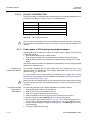
Installation of the LCT software . . . . . . . . . . . . . . . . . . . . . . . . . . . . . 2-261
System requirements . . . . . . . . . . . . . . . . . . . . . . . . . . . . . . . . . . . . . . . 2-261
Installation of the software . . . . . . . . . . . . . . . . . . . . . . . . . . . . . . . . . . . 2-261
Establish the communication via TCP (optional) . . . . . . . . . . . . . . . . . . 2-262
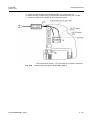
Installation of a Port Server. . . . . . . . . . . . . . . . . . . . . . . . . . . . . . . . . . . 2-262
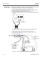
Configure a Digi Port Server . . . . . . . . . . . . . . . . . . . . . . . . . . . . . . . . . . 2-263
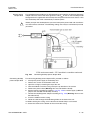
Configure the Cisco 25xx Router Family (IOS Version 11.2) . . . . . . . . . 2-263
Configure the DCB SS01 Port Server. . . . . . . . . . . . . . . . . . . . . . . . . . . 2-265
Configure the Chase IOLAN+ Port Server . . . . . . . . . . . . . . . . . . . . . . . 2-267
Configure the EtherQuinx / Cobox port server . . . . . . . . . . . . . . . . . . . . 2-268
Lantronix ETSxP . . . . . . . . . . . . . . . . . . . . . . . . . . . . . . . . . . . . . . . . . . . 2-270
Command line parameter (optional) . . . . . . . . . . . . . . . . . . . . . . . . . . . . 2-272
3
References . . . . . . . . . . . . . . . . . . . . . . . . . . . . . . . . . . . . . . . . . . . . . AP-1
4
Abbreviations . . . . . . . . . . . . . . . . . . . . . . . . . . . . . . . . . . . . . . . . . . AP-3
5
Index . . . . . . . . . . . . . . . . . . . . . . . . . . . . . . . . . . . . . . . . . . . . . . . . . . . AP-5
A3118-X300-M100-1-76D1
AD – 11
Installation Manual
AD – 12
Installation
ULAF+ V4.2
A3118-X300-M100-1-76D1
Installation
ULAF+ V4.2
Installation Manual
1 Introduction
ULAF+ is a modular system for transmitting TDM based 2 Mbit/s- and nx64 kbit/s data
and voice signals. The signals are transmitted either via
• copper cables, using HDSL technology, via
• copper cables, using SHDSL technology (one wire pair) or via
• an optical fiber cable, using TCM (Time Compression Multiplex) technology at a
wavelength of 1300 nm.
The modular concept of ULAF+ allows the use of one and the same basic module, both
in the subrack and in the desktop unit. The Network Operator or the customer is therefore able to adapt the basic module to his specific requirements by equipping it with
various interface modules.
In detail, the system consists of the following components:
• the subrack
• the Operating & Maintenance Interface unit (OMI/OMI SNMP)
• the HTU/STU/STU2/QSTU/STU4/BSTU/BSTU4/LR-DSTU/BOTU/OTU termination
units
• the G.703 termination units GTU (Interface converter)
• the HDSL regenerator (REG)
• the SHDSL regenerators SRU and BSRU
• a series of submodules (such as remote power supply, subscriber interfaces) for
individual configuration of the system.
For local operation and maintenance of ULAF+, the system can be
• controlled and configured via a Local Craft Terminal (LCT) which is connected to the
OMI/OMI SNMP or to the desktop units and/or
• controlled and configured via a DIP switch (only applies to pure 2 Mbit/s applications).
Visual indication of the operating status is provided by LEDs on the front of the plug-in
units or the desktop units.
The AccessIntegrator management software is used for centralized operation and maintenance.
1.1
Documentation overview
The ULAF+ customer documentation comprises the following manuals:
• Technical Description (TED)
The Technical Description for ULAF+ gives an overview of the structure and function
of the system and all its components. The subsystem descriptions contain detailed
information about the individual submodules, a complete product overview and
detailed technical data about the system.
• Installation Manual (IMN)
The Installation Manual contains installation notes for the individual system components or submodules. The IMN contains tables and diagrams with the Pin assignments of the connectors, settings of the address switches and the operating
elements and module-specific alarm tables.
• User Manual (UMN)
The User Manual describes all the procedures of the LCT required for the operation
and administration of a fully functioning system. If errors do occur, cross references
are provided so that the normal operating mode can be restored.
A3118-X300-M100-1-76D1
1–1
Installation Manual
Installation
ULAF+ V4.2
ULAF+ documentation is supplemented by the manuals for the AccessIntegrator
management software:
• System Description (TED)
is intended for those interested in learning more about the overall structure and functional scope of the software.
• Installation and System Administration Manual (ADMN)
The installation part of the manual is intended for anyone involved in the installation
and configuration of the software. It describes the procedures for initial installation
of the system, installation of a new version of the software and modification of the
existing OS configuration.
The administration part is intended to be used by anyone who configures the software for other users. It describes the tasks which must be performed in order to
guarantee trouble-free and reliable management of the network elements.
• User Manual (UMN)
is intended for those who are monitoring and maintaining the network elements by
means of the AccessIntegrator.
1.2
Notes on product safety
It is inevitable that in electrical systems certain parts of the equipment will be under
voltage. A number of parts can also become very hot during operation.
Ignoring this situation and the warnings given can result in personal injury or damage to
property.
1.2.1
Representation conventions
This manual uses various different types of indiction to make you aware of product
safety:
•
i
Information gives useful notes which pertain to particular situations and specifically draw
the reader’s attention to them. Information will be highlighted in the text using an information symbol.
•
!
1–2
Information
Warning
Warnings give important information, which it is vital to follow to prevent damage. Warnings will be highlighted in the text using a warning symbol.
A3118-X300-M100-1-76D1
Installation
ULAF+ V4.2
Installation Manual
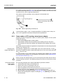
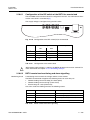
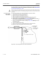
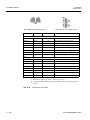
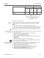
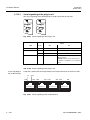
1.2.2
Handling modules and submodules
Fig. 1.1
!
Inserting/ removing
modules
!
!
ESD symbol
Modules that bear the ESD symbol are equipped with electrostatic sensitive devices, i.e.
the appropriate safety precautions must be observed when handling these modules.
The plug-in units can be removed and inserted while the power is still applied.
To remove and insert plug-in units, the screws in the front of the plug-in units should be
undone.
The voltage must be interrupted before the submodules are removed and inserted.
If neither the ULAF+ desktop unit nor the terminal device are earthed, to prevent static
discharge you must connect the terminal device before switching on the ULAF+ desktop
unit.
A wrist band must always be worn when unpacking, packing, touching, removing or
inserting modules bearing the ESD symbol, see Fig. 1.1, This wrist band is to be
grounded when working with ULAF+ components. This will ensure that electrostatically
sensitive components are not damaged.
Basically the conductor tracks or components on the modules may not be touched. The
modules may only be held by their edges.
Once they have been removed, place the modules in the conductive plastic envelope
provided and then store them or dispatch them in special boxes or special transport
cases bearing ESD symbol.
To avoid further damage, defective modules are to be handled with as much care as
new modules.
Modules located in an enclosed, unopened housing are always protected.
European Standard EN50082-1 contains information on correct handling of electrostatic
sensitive modules.
Disposal of equipment and units
All electrical and electronic products should be disposed of separately from the municipal waste stream via designated collection facilities appointed by the government or the
local authorities.
The correct disposal and separate collection of your old appliance will help prevent
potential negative consequences for the environment and human health. It is a precondition for reuse and recycling of used electrical and electronic equipment.
For more detailed information about disposal of your old appliance, please contact your
SIEMENS partner.
A3118-X300-M100-1-76D1
1–3
Installation Manual
Installation
ULAF+ V4.2
The statements quoted above are only fully valid for equipment which is installed in the
countries of the European Union and is covered by the directive 2002/96/EC. Countries
outside the European Union may have other regulations regarding the disposal of electrical and electronic equipment.
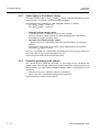
1.2.3
!
1.3
Stacking the desktop units
Because of the generated heat you may stack the desktop units only in a room with
capacity 20 degrees above zero.
It is recommend to use a 19” subrack to accommodate one or more desktop models.
This subrack provides space for 8 desktop models included their enclosure. You will find
ordering information in the ULAF+ price list.
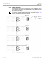
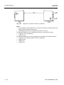
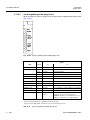
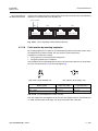
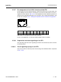
Notes on protection against laser radiation
Normal operation
In normal operation the unit is fully encapsulated. It therefore belongs to Laser class 1.
Interruption of a glass
fiber
Where there is an interruption to a glass fiber (fiber break or connector unplugged from
the device) an automatic laser shutdown circuit is activated. The resulting average
optical power in this case is 0.025 mW (OTU) and is classified as harmless, as defined
by Laser class 1. The light output in conjunction with the BOTU/QOTU depends on the
SFP modules used. Optical interfaces that are not used should be fitted with protective
caps to prevent contamination.
Dangerous fault
The device correspond to the Laser class 1 in any disturbances. The safety precautions
(see Fig. 1.2) should be noted.
- Escape of invisible laser radiation -
- Do not view using optical instruments -
LASER CLASS 1
Fig. 1.2
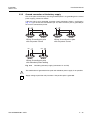
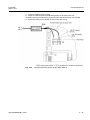
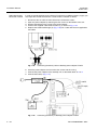
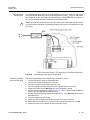
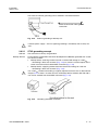
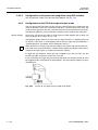
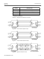
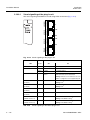
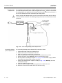
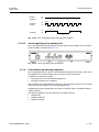
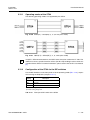
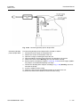
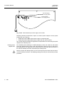
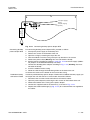
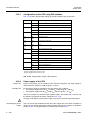
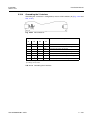
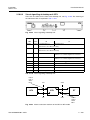
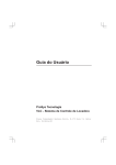
1.4
Overvoltage protection
Fig. 1.3
1–4
Laser safety precautions
Overvoltage protection
A3118-X300-M100-1-76D1
Installation
ULAF+ V4.2
Installation Manual
Fig. 1.3 shows an example with a SHDSL loop with some (probably) inserted SRUs.
Overvoltage (2) caused by i.e. lightning or mains can occur anywhere on the loop.
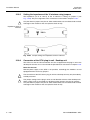
1.4.1
Protection of a network element
An overvoltage protection as a primary stage is mandatory in connection with any
ULAF+ network elements (3). Usually it is a 3-electrode-arrestor with a spark-over
voltage of > 130 V. When the desktop model is remote powered by 180 V the spark-over
voltage has to be > 200 V and the desktop model shall be earthed (4).
1.4.2
Protection of the SHDSL regenerator (SRU)
The SHDSL regenerator needs no additional protection. If possible the SRU should be
earthed at the appropriate Pin (1) (chapter 2.21.2). This causes the overvoltage to be
shorted to earth (path a). Otherwise the overvoltage will appear at the next line section
(path b).
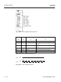
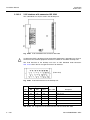
1.4.3
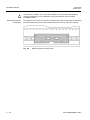
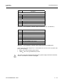
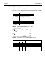
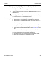
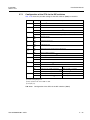
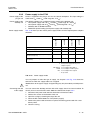
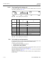
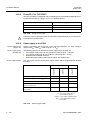
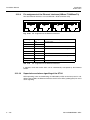
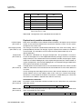
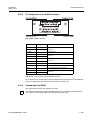
Requirements of the 3-electron-arrester for primary protection
Tab. 1.1 shows for example the technical characteristics of a 3-electron-arrester by the
EPCOS company. The type is called T23-A230XF4.
DC spark-overvoltage in ionized mode
> 130 V or > 200 V
Impulse spark-overvoltage at 100 V/μs
< 350 V
Impulse spark-overvoltage at 1 kV/μs
Nominal impluse discharge current
20 kA (wave 8/20μs)
Single impulse discharge current
25 kA (wave 8/20μs)
Nominal alternation discharge current (50 Hz, 1 s)
10 A
Single alternation discharge current (50 Hz, 9 cycles)
50 A
Insulation restistance at 100 VDC (a or b to center)
> 10 GΩ
Glow voltage
approx. 200 V
Tab. 1.1
1.5
1.5.1
< 450 V
Requirements of the 3-electron-arrester
EMC and product safety
EMC
The CE conformity declaration for the product is met when the installation and cabling
is carried out in compliance with the instructions in the ULAF+ Installation Manual
(Chap. 2). Where necessary project-specific documents should be taken into account.
Deviations from the specifications or independent changes made during installation, e.g.
the use of cable types with a lower shielding mass, can lead to the CE protection requirements being violated. In such cases the conformity declaration will be invalidated.
Responsibility for any problems that may occur thereafter then lies with the person
responsible for deviating from the specifications.
A3118-X300-M100-1-76D1
1–5
Installation Manual
Installation
ULAF+ V4.2
1.5.2
!
Product safety
Before you open the desktop device you must interrupt the feed and also disconnect the
interface connector. You have to guarantee the easy access to the main socket.
All work on the open unit may only be performed by authorized specialists (maintenance
staff). Considerable danger (electric shock, fire) for maintenance staff and the user can
be incurred with unauthorized opening of or improper work on the unit.
The unit complies with:
• The relevant safety regulations for IT installations (EN 60950-1 and EN 60950-21).
It is recommended that all interface connections (e.g. routers) be set up first, and
only then should the ULAF+ desktop unit be connected with the 230 volt mains
(prevention of damages caused by electrical discharges).
• EU Directive, RoHS 2002/95/EC, with regard to dangerous substances in electrical
and electronic equipment.
A prerequisite is that all connected devices also meet these requirements.
Non-adherence to specifications or modifications to setup (for example, use of SFP
modules not approved for this product) can lead to violation of security provisions. This
would invalidate the Declaration of Conformity. Liability for any associated problems
then lies with the person responsible for the modifications or for non-adherence to specifications.
1–6
A3118-X300-M100-1-76D1
Installation
ULAF+ V4.2
Installation Manual
2 Hardware and Software Installation
This chapter describes how to install the hardware components and the management
software (LCT) of ULAF+:
• The ULAF+ subrack (S3105-B128-A210) (Chapter 2.2)
• The ULAF+ subrack (S3105-B128-C210 / -C211) (Chapter 2.3)
• The Operating and Maintenance Interface OMI (Chapter 2.4)
• The Operating and Maintenance Interface OMI SNMP (Chapter 2.5)
• The HTU termination unit (Chapter 2.6)
• The STU termination unit (Chapter 2.7)
• The STU termination unit with G.703 64 kbit/s (codirectional) (chapter 2.8)
• The STU2 termination unit (Chapter 2.9)
• The BSTU termination unit (Chapter 2.10)
• The QSTU termination unit (Chapter 2.11)
• The STU4 termination unit (Chapter 2.12)
• The BSTU4 termination unit (Chapter 2.13)
• The Ethernet over TDM Inverse Multiplexer GTU4 (Chapter 2.14)
• The Long Reach termination unit LR-DSTU (Chapter 2.15)
• The OTU termination unit (Chapter 2.16)
• The BOTU/QOTU termination unit (Chapter 2.17)
• The G.703 termination unit GTU (Chapter 2.18)
• The Interface- and submodules (Chapter 2.19)
• The HDSL regenerator (Chapter 2.20)
• The SHDSL regenerator SRU (Chapter 2.21)
• The SHDSL regenerator BSRU (Chapter 2.22)
• The Housing for xDSL regenerators (Chapter 2.23)
• Installation of the LCT software (Chapter 2.24)
2.1
General requirements/check list
The following tasks must be carried out for each system component before/during installation:
• The scope of delivery and installation are complete:
– Check the delivery for completeness using the parts list.
– Cabling and placement of the shelves must be checked for each individual system component using the installation instructions.
– The plug-in units must be fitted securely.
– Both the external and the internal cabling are correct.
• The hardware is in the as-delivered state:
– Check the hardware-specific settings of the plug-in units and the submodules
– The system voltage is connected and continuously available.
• There is ULAF+ and, if required, AccessIntegrator documentation on site (chapter
3).
• The LCT is installed and operational (if the system is not configured via the DIP
switches) (chapter 2.24).
A3118-X300-M100-1-76D1
2–1
Installation Manual
Installation
ULAF+ V4.2
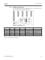
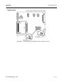
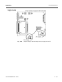
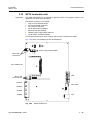
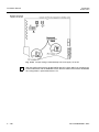
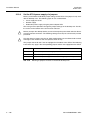
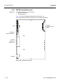
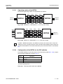
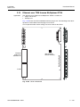
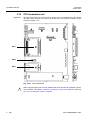
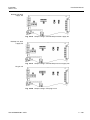
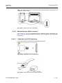
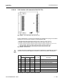
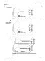
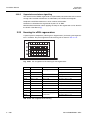
2.2
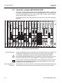
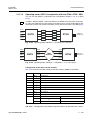
The ULAF+ subrack (S3105-B128-A210)
The ULAF+ subrack accepts double eurocard size plug-in units. Slot 0 is reserved for
the Operating and Maintenance Interface unit (OMI/OMI SNMP). The remaining slots
can either be equipped with HTU-, STU-, STU2-, BSTU-, QSTU-, STU4-, BSTU4-,
GTU4-, BOTU-, OTU- or GTU plug-in units.
This chapter describes the settings which must be made on the subrack for trouble-free
operation.
OMI
QSTU
SNMP
STU2
PWR
PWR
ALARM
A
UA
NU
ACK
ACK
G.703
LOS-T/V
LFA-T/V
B
C
PWR
LOS/
LFA-T/V
LOS/
LFA-U
AIS-U
E6-U
E6-U
MAINT
MAINT
O
F
F
D
1
STU
PWR
LOS/
LFA-T/V
LOS/
LFA-U
AIS-U
2bR
1/3a
O
F
F
QSTU
2bR
1/3a
SHDSL
LOS-U
LFA-U
2
3
ALARM
ALARM
A
B
C
G.703
B
LOS-T/V
LFA-T/V C
D
D
1
1
SHDSL
LOS-U
LFA-U
3
O
F
F
3
GTU4
GTU4
PWR
PWR
ALARM
ALARM
LOA-Rx
LOA-Rx
LOA-Tx
PWR
LOS/
LFA-T/V
LOS/
LFA-U
AIS-U
LOA-Tx
MIR-Tx
E6-U
E6-U
MIR-Tx
MCS
MAINT
MAINT
MCS
ALARM
LOS/
LFA-U
AIS-U
LOA-Rx
E6-U
E6-U
MAINT
MAINT
O
F
F
2bR
1/3a
O
F
F
1
2
D
A
B
C
D
1/3a
A
B
C
D
1/3a
LAN
A
LCT
D
D
D
SHDSL-U
SHDSL-U
SHDSL-U
SHDSL-U
64k
SHDSL-U
SHDSL-U
SIEMENS
SIEMENS
SIEMENS
SIEMENS
Fig. 2.1
Cable compartment
CS
CM
MAINT
RT
SIEMENS
SIEMENS
SIEMENS
COT
10/100baseT
10/100baseT
P1
P1
P2
P2
P3
P3
P4
P4
P1
P1
P2
P2
P3
P3
P4
P4
P1
P2
P3
P4
HDSL-U
SHDSL-U
G.703-V
SIEMENS
SIEMENS
SIEMENS
SIEMENS
SIEMENS
OPTICAL-U
SIEMENS
SIEMENS
SIEMENS
ULAF+ subrack (S3105-B128-A210)
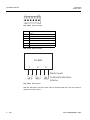
A cable compartment can be fastened with screws to the bottom of the 19” subrack. The
compartment is obtainable as an accessory (see [1]) and is used for cable laying.
!
For subracks arranged one on top of the other and fully equipped with RPSII or
STU2/BSTU/QSTU/STU4/BSTU4 with activated RPS, it is imperative that there is a distance of 3 height units (6 HU = subrack height) for a trouble-free heat dissipation.
i
In the subrack a maximum of 32 SHDSL lines can be remotely fed. In order to be able
to operate more than 32 SHDSL lines with remote power feeding, you must use the
S3105-B128-C210 subrack (chapter 2.3).
Mounting bracket for
ETSI racks
2–2
SIEMENS
3a
4
MAINT
OPTICAL-U
SIEMENS
2
3
P4
G.703-T 120Ω
MAINT
O
F
F
OUT
OUT
SHDSL-U
IN
G.703-T/V 75 Ω
SHDSL-U
G.703-T/V 120 Ω
NMS/10BT
CM
E6-V
MCS
1
G.703-T/V 120 Ω
C
MIR-Tx
2bR
1/3a
IN
C
ISDN-BA
O
F
F
G.703-T/V 75 Ω
C
ISDN-BA
2bR
1/3a
G.703-T/V 120 Ω
B
G.703-T/V 120 Ω
B
ISDN-BA
B
P3
G.703-T/V 120 Ω
A
G.703-T/V 120 Ω
A
CS
P2
O
F
F
LOA-Tx
D
10/100baseT
P1
MAINT
LOA-Rx
DCE
1/3a
E6-U
MAINT
PWR
LOS/
LFA-T
LOS/
LFA-V
AIS-V
ALARM
V.36
A
B
C
D
C
MAINT
10/100baseT
E6-U
MCS
GTU
PWR
DCE
2bR
COT
MIR-Tx
STU4
X.21
A
B
C
D
RT
LOA-Tx
PWR
LOS/
LFA-T/V
LOS/
LFA-U
AIS-U
G.703
LOS-V
LFA-V
B
OTU
PWR
LOS/
LFA-T/V
LOS/
LFA-U
AIS-U
DCE
2bR
G.703
LOS-V
LFA-V
B
A
OTU
V.36
A
B
C
D
A
MAINT
DCE
2bR
2bR
1/3a
C
DCE
A
B
C
D
O
F
F
4
Collision
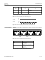
10baseT Bridge
MAINT
2bR
1/3a
3
Activity
MAINT
STU2
PWR
LOS/
LFA-T/V
LOS/
LFA-U
AIS-U
LOS-T/V
Integrity
4
MAINT
HTU
PWR
2bR
1/3a
SHDSL
LOS-U
LFA-U
2
STU4
PWR
X.21
4
G.703
LOS-T/V
LFA-T/V
STU
PWR
LOS/
LFA-T/V
LOS/
LFA-U
AIS-U
X.21
4
PWR
A
2
STU2
QSTU
PWR
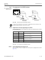
To enable you to use the 19” subrack in an ETSI rack you must break out the mounting
bracket located on the back of the subrack and attach it to one side of the subrack.
A3118-X300-M100-1-76D1
Installation
ULAF+ V4.2
Installation Manual
Fig. 2.2
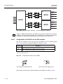
2.2.1
Mounting bracket for ETSI racks
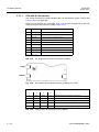
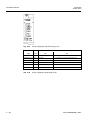
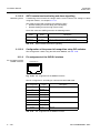
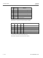
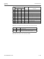
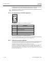
Backplane of the subrack
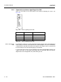
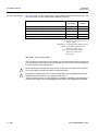
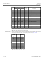
You can configure the cascading of the subracks (chapter 2.2.6) and termination of the
OMI bus using the DIP switches on the backplane.
Fig. 2.3
Backplane of the subrack
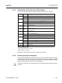
DIP switch 1
DIP switch 2
DIP switch 3 1)
DIP switch 4
ON
ON
ON
--
Subrack address 11)
Slots 1 ... 16
OFF
ON
ON
--
Subrack address 2
Slots 18 ... 33
ON
OFF
ON
--
Subrack address 3
Slots 35 ... 50
OFF
OFF
ON
--
Subrack address 4
Slots 52 ... 67
Description
Slot number
terminated 1)
--
--
--
ON
OMI bus
--
--
--
OFF
OMI bus open
1) Default settings
Tab. 2.1
DIP switches of the backplane
A3118-X300-M100-1-76D1
2–3
Installation Manual
Installation
ULAF+ V4.2
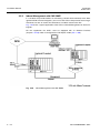
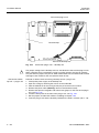
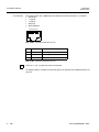
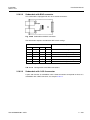
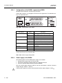
2.2.2
External connections of the subrack
Fig. 2.4
External connections of the subrack (backplane)
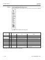
In the following tables, you will find the Pin assignment of the individual connectors for
the external connections of the subrack. The numbering relates to Fig. 2.15.
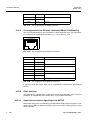
Pin
1
Input 1
2
Grounding GND
3
Input 2
4
Grounding GND
5
Input 3
6
Grounding GND
7
Input 4
8
Grounding GND
Tab. 2.2
i
Description
Pin assignment - Subrack alarm input (connector X6)
Provided for subsequent expansions. The alarm input is not supported in the current
firmware version of the OMI/OMI SNMP.
Conductor
1 Inner conductor
Clock
1 Outer conductor
Shield
Tab. 2.3
2–4
Description
Pin assignment - Subrack clock 75 Ω (connector X8)
A3118-X300-M100-1-76D1
Installation
ULAF+ V4.2
Installation Manual
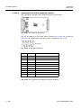
Pin
Description
1
Not assigned
2
Not assigned
3
Grounding GND (shield)
4
Clock a
5
Clock b
6
Grounding
7
Grounding
8
Grounding
Tab. 2.4
Pin assignment - Subrack 120 Ω clock (connector X10)
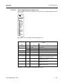
Pin
Description
Supply 1 (Connector X1)
1
48 V / 60 V (-)
2
48 V / 60 V (+)
3
Grounding, GND
Supply 2 (Connector X2)
1
48 V / 60 V (-)
2
48 V / 60 V (+)
3
Grounding, GND
Tab. 2.5
Pin assignment - Subrack supply (connector X1/X2)
Pin
Description
1
Grounding
2
Urgent alarm, relay contact 1
3
Urgent alarm, relay contact 2
4
Non-urgent alarm, relay contact 1
5
Non-urgent alarm, relay contact 2
6
Alarm acknowledgment, relay contact 1
7
Alarm acknowledgment, relay contact 2
8
Grounding
Tab. 2.6
Pin assignment - Subrack alarm output (connector X7)
In the case of the alarm output Pin 2 is connected to Pin 3; Pin 4 to Pin 5 and Pin 6 to
Pin 7. Contact rating
• 60 V/0.2 A for an floating relay contact
• 100 V/0.2 A for a grounded relay contact.
A3118-X300-M100-1-76D1
2–5
Installation Manual
2.2.3
Installation
ULAF+ V4.2
Power supply to the subrack, fusing
The subrack power supply is -48 VDC or -60 VDC . A redundant power supply is provided
using connectors X1 and X2 and is decoupled via diodes. Each path is protected by a
8 A fuse. 5x20 mm Pin-type fuses with a high breaking capacity (sand filled) must be
used.
• Operation with one voltage source:
⇒ Connector X1 and X2 must be short circuited
Failure of the power supply or the power supply dropping below a threshold of
around 36 VDC triggers an urgent alarm.
• Operation with redundant power supply:
⇒ Power sources are connected to separately connector X1 or connector X2
Failure of one power supply or the power supply dropping below a threshold of
around 36 VDC triggers an alarm.
Failure of one power supply or the power supply dropping below a threshold of around
36 VDC triggers a non-urgent alarm.
Screw terminals are provided for connecting the power supply (max. conductor cross
section 2.5 mm2). The upper part of the connector can be pulled off for easier handling.
You must provide 8 AT fuses for each power connector (X1 and X2).
2.2.4
Grounding of the subrack
The subrack must be effectively grounded, i.e. the casing must be connected with
ground in such a way that the requirements (cable line diameter, ground resistance, labeling, contacts, etc.) fulfill safety standard EN 60950-1:2006. It is grounded in the following way
• normally via the rack in which the subrack is installed, or
• with a screw and a serrated lock washer on the side panel.
The line diameter must not be smaller than the diameter of feed line, but must be at least
1.5 mm2.
2–6
A3118-X300-M100-1-76D1
Installation
ULAF+ V4.2
Installation Manual
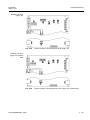
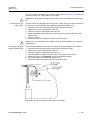
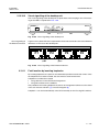
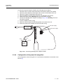
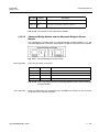
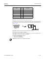
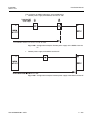
2.2.5
Ground connection of the battery supply
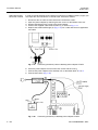
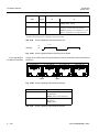
Shall one of the poles of the battery be grounded and there is no grounding for the central power supply, proceed as follows:
For a grounded positive pole Pin 2 is connected to Pin 3 on supply connectors X1 or X2
(see Fig. 2.4) and for a grounded negative pole Pin 1 to Pin 3.
Example: For operation with a -48 VDC / -60 VDC power supply the unit must be wired
as follows (see Fig. 2.5):
1. P = 0 V
2. M = -48 VDC / -60 VDC
3. M connected to G (X2)
1. P = 0 V
2. M = -48 VDC / -60 VDC
3. P connected to G (X2)
M
P G
X1
M
P G
X2
Grounding of plus pole
M
P G
M
X1
P G
X2
Grounding of minus pole
(Viewed from the rear towards the backplane)
Fig. 2.5
i
Grounding of battery supply (connectors X1 and X2)
Supply voltage supervision only functions if the positive pole is grounded.
A3118-X300-M100-1-76D1
2–7
Installation Manual
Installation
ULAF+ V4.2
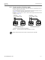
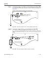
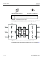
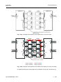
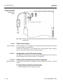
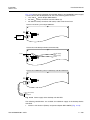
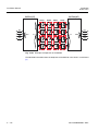
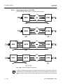
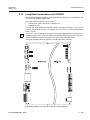
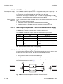
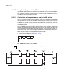
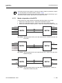
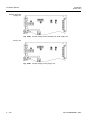
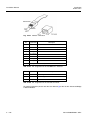
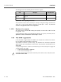
2.2.6
Subrack cascading
Fig. 2.6
Cascading the subrack
A maximum of four subracks can be cascaded. When they are cascaded, only one Operating and Maintenance Interface unit (OMI/OMI SNMP) may be used. The termination
units can be used as required.
i
In order to be able to cascade subracks equipped with QSTUs, the QSTUs must have
Firmware-ID 349 at least.
Each subrack needs a unique address. You define the address by setting the DIP
switches on the backplane of the subrack, see Fig. 2.3 and Tab. 2.1.
The OMI bus on the last subrack must be terminated when the subracks are cascaded.
The termination is set using the DIP switches on the backplane, see Fig. 2.4 and
Tab. 2.1.
i
2–8
The overall length of the up to three cascading cables may not exceed 20 m.
A3118-X300-M100-1-76D1
Installation
ULAF+ V4.2
Installation Manual
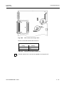
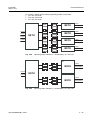
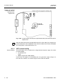
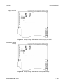
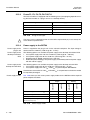
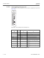
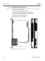
2.3
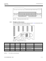
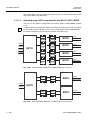
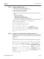
The ULAF+ subrack (S3105-B128-C210 / -C211)
The ULAF+ subrack accepts double eurocard size plug-in units. Slot 0 is reserved for
the Operating and Maintenance Interface unit (OMI/OMI SNMP). The remaining slots
can either be equipped with HTU-, STU-, STU2-, BSTU-, STU4-, BSTU4-, QSTU-,
GTU4-, LR-DSTU-, BOTU-, OTU- or GTU plug-in units.
This chapter describes the settings which must be made on the subrack for trouble-free
operation.
F1
48V / 20A
60V /15A
F2
QSTU
STU2
ALARM
A
C
G.703
B
LOS-T/V
LFA-T/V C
D
D
1
1
1
2
3
4
MIR-Tx
SHDSL
LOS-U
3
4
MAINT
3
D
D
MAINT
RT
COT
10/100baseT
4
MAINT
CS
CM
MAINT
CS
10/100baseT
3
CM
MAINT
RT
10/100baseT
COT
A
A
B
A
B
MAINT
OFF
A
B
A
B
AUX
P4
P4
P4
P1
P1
P2
P2
P3
P3
P4
P4
ON
2bR
1/3a
COT
A RS232
A
B
SFP2
LOS AIS LOS AIS 1
SHDSL-U
G.703-T/V 120 Ω
AUX
3a
OC
RPS
DCE
P3
MAINT
O
F
F
UC
RPS
LOS AL LOS AL
P3
E6-V
LOS-U
LFA-U
B
10/100baseT
P3
SFP2
P3
SFP1
P3
AUX
P2
P3
P2
G.703-V
OPTICAL-U
2
2
SIEMENS
LOS-T/V
LFA-T/V
B
G.703
P2
P2
PWR
LOS/
LFA-T
LOS/
LFA-V
AIS-V
ALARM
A
P1
P2
LOS AL LOS AL
P1
SHDSL
LOS AIS LOS AIS 1
P1
SHDSL-U
COT
RT
B
P1
SHDSL-U
RT
GTU
PWR
MNT
10/100baseT
P1
P2
AL
V.36
COT
C
2
SFP1
P1
SHDSL
Fig. 2.7
SIEMENS
4
C
G.703
LOS-V
LFA-V
B
2bR
1/3a
LRDSTU
BOTU
PWR
G.703D
D
SIEMENS
SHDSL
LOS-U
G.703
LOS-V
LFA-V
MAINT
O
F
F
G.703-T/V 120 Ω
D
SIEMENS
B
MCS
1
10/100baseT
D
SHDSL-U
2
MCS
A
DCE
C
SHDSL-U
A
AUX
C
MCS
1
E6-U
V.36
RT
MCS
COT
A
B
MNT
P3
C
i
LOA-Tx
MIR-Tx
PWR
LOS/
LFA-T/V
LOS/
LFA-U
AIS-U
COT
P2
B
!
LOA-Tx
MIR-Tx
P1
B
Cable compartment
LOA-Tx
MIR-Tx
P2
B
SIEMENS
LOA-Tx
MIR-Tx
10/00BT G.703 A G.703 B
A
10/00BT G.703 A G.703 B
SIEMENS
LOA-Tx
P1
A
SHDSL-U
RT
P2
10/00BT
SIEMENS
1/3a
PWR
LOA-Rx
10/100baseT
A
G.703-T/V 120 Ω
SHDSL-U
1/3a
A
B
C
D
ALARM
LOA-Rx
P1
1/3a
2bR
ALARM
LOA-Rx
10/00BT
A
B
C
D
2bR
A
B
C
D
ALARM
LOA-Rx
G.703D
A
B
C
D
MAINT
ALARM
MAINT
X.21
2bR
LCT
NMS/10BT
MAINT
X.21
A
B
C
D
3
ALARM
RT
OTU
AL
LOA-Rx
MCS
4
MAINT
A
B
C
D
SHDSL
LOS-U
LFA-U
2
BOTU
PWR
G.703C
4
G.703
LOS-T/V
LFA-T/V
STU4
G.703C
SHDSL
LOS-U
LFA-U
2
DCE
3
COT
A
B
A
B
PWR
ALARM
DCE
SHDSL
LOS-U
LFA-U
2
RT
A
GTU4
PWR
G.703B
1
2bR
1/3a
ALARM
GTU4
PWR
LOS AIS LOS AIS LOS AIS LOS AIS
MAINT
O
F
F
D
ALARM
BSTU4
PWR
G.703B
ACK
C
E6-U
BSTU
PWR
PWR
G.703A
ACK
G.703
LOS-T/V
LFA-T/V
B
ALARM
MAINT
BSTU4
QSTU
PWR
LOS AIS LOS AIS LOS AIS LOS AIS
NU
QSTU
PWR
G.703A
UA
BSTU
PWR
LOS/
LFA-T/V
LOS/
LFA-U
AIS-U
PWR
PWR
RS232
OMI
SNMP
SIEMENS
SIEMENS
SIEMENS
SIEMENS
SIEMENS
SIEMENS
SIEMENS
SIEMENS
SIEMENS
SIEMENS
ULAF+ subrack (S3105-B128-C210 / -C211)
A cable compartment can be fastened with screws to the bottom of the 19” subrack. The
compartment is obtainable as an accessory (see [1]) and is used for cable laying.
For subracks arranged one on top of the other and fully equipped with HTU/RPSII or
STU/STU2/BSTU/QSTU/STU4/BSTU4 with activated RPS, it is imperative that there is
a distance of 3 height units (6 HU = plug-in unit height, on top edge of the rack, without
connector panel) for a trouble-free heat dissipation.
In the subrack a maximum of 64 SHDSL lines can be remotely fed. In contrast to the
subrack described above, you can operate no more than 32 SHDSL lines with remote
power feeding.
A3118-X300-M100-1-76D1
2–9
Installation Manual
Installation
ULAF+ V4.2
!
Mounting bracket for
ETSI racks
The subrack is a built-in unit. It must be installed in an environment that complies
with the requirements of a fire protection casing according to safety standard
EN 60950-1:2001.
To enable you to use the 19” subrack in an ETSI rack you must break out the mounting
bracket located on the back of the subrack and attach it to one side of the subrack.
Fig. 2.8
2 – 10
Mounting bracket for ETSI racks
A3118-X300-M100-1-76D1
Installation
ULAF+ V4.2
Installation Manual
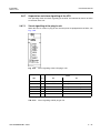
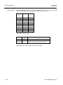
2.3.1
Backplane of the subrack
You can configure the cascading of the subracks (chapter 2.3.6) and termination of the
OMI bus using the DIP switches on the backplanes.
Fig. 2.9
DIP switch 1
DIP switch 2
Backplane of the subrack
DIP switch 3 1)
DIP switch 4
Description
1)
Slot number
ON
ON
ON
--
Subrack address 1
OFF
ON
ON
--
Subrack address 2
Slots 18 ... 33
ON
OFF
ON
--
Subrack address 3
Slots 35 ... 50
OFF
OFF
ON
--
Subrack address 4
Slots 52 ... 67
Slots 1 ... 16
terminated 1)
--
--
--
ON
OMI bus
--
--
--
OFF
OMI bus open
1) Default settings
Tab. 2.7
DIP switches of the backplane
A3118-X300-M100-1-76D1
2 – 11
Installation Manual
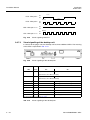
2.3.2
Installation
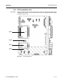
ULAF+ V4.2
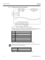
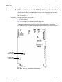
External connections of the subrack
Fig. 2.10
External connections of the subrack (backplane)
In the following tables, you will find the Pin assignment of the individual connectors for
the external connections of the subrack
Conductor
Description
1 Inner conductor
Clock
1 Outer conductor
Shield
Tab. 2.8
Pin assignment - Subrack clock 75 Ω (connector SYNC 75 Ω )
Pin
2 – 12
Description
1
Not assigned
2
Not assigned
3
Grounding GND (shield)
4
Clock a
5
Clock b
6
Grounding
7
Grounding
8
Grounding
Tab. 2.9
Pin assignment - Subrack 120 Ω clock (connector SYNC 120 Ω )
Fig. 2.11
Subrack supply connector Power 1 and Power 2
A3118-X300-M100-1-76D1
Installation
ULAF+ V4.2
Installation Manual
Pin
Description
Supply 1 (Connector: Power 1)
A1
48 V / 60 V (+)
A2
Grounding, GND
A3
48 V / 60 V (-)
Supply 2 (Connector: Power 1)
A1
48 V / 60 V (+)
A2
Grounding, GND
A3
48 V / 60 V (-)
Tab. 2.10
Pin assignment - Subrack supply (connector Power 1 and Power 2)
Pin
Description
1
Grounding
2
Urgent alarm, relay contact 1
3
Urgent alarm, relay contact 2
4
Non-urgent alarm, relay contact 1
5
Non-urgent alarm, relay contact 2
6
Alarm acknowledgment, relay contact 1
7
Alarm acknowledgment, relay contact 2
8
Grounding
Tab. 2.11
Pin assignment - Subrack alarm output (connector ALARM OUT)
In the case of the alarm output Pin 2 is connected to Pin 3; Pin 4 to Pin 5 and Pin 6 to
Pin 7. Contact rating
• 60 VDC / 0.2 A for an floating relay contact
• 100 VDC / 0.2 A for a grounded relay contact.
!
The setup is only fully separated from the primary power supply when both connectors
Power 1 and Power 2 have been unplugged.
A3118-X300-M100-1-76D1
2 – 13
Installation Manual
2.3.3
Installation
ULAF+ V4.2
Power supply to the subrack, fusing
The subrack power supply is -48 VDC or -60 VDC . Power is supplied redundantly via connectors Power 1 and Power 2 and is decoupled with diodes.
Recommended fuse protection for a fully equipped subrack is as follows:
– For a 48 VDC supply → 20 A fuse
– For a 60 VDC supply → 16 A fuse
•
•
Operation with one voltage source:
⇒ Connector Power 1 and Power 2 must be short circuited
Failure of the power supply or the power supply dropping below a threshold of
around 36 VDC triggers an urgent alarm.
Operation with redundant power supply:
⇒ Power sources are connected to separately connector Power 1 or connector
Power 2.
Failure of one power supply or the power supply dropping below a threshold of
around 36 VDC triggers an alarm.
The unit is connected with a 3W3 D-Sub mixed-pole connector with high current contacts. The cable must have a line diameter of 2.5 mm2.
You must fuse the cables to the subrack with 20 AT.
2.3.4
Protective grounding of the subrack
The subrack must be effectively grounded, i.e. the casing must be connected with
ground in such a way that the requirements (cable line diameter, ground resistance, labeling, contacts, etc.) fulfill safety standard EN 60950-1:2006. It is grounded in the following way
• normally via the rack in which the subrack is installed, or
• with a screw and a serrated lock washer on the side panel.
The line diameter must be at least 2.5 mm2.
2 – 14
A3118-X300-M100-1-76D1
Installation
ULAF+ V4.2
Installation Manual
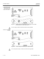
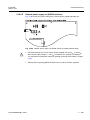
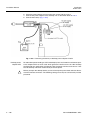
2.3.5
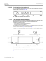
Ground connection of the battery supply
One of the poles of the battery must be grounded (there is no grounding for the central
power supply), proceed as follows:
If the plus pole is to be grounded, on power supply connectors Power 1 and Power 2
(Fig. 2.12) pin A2 must be connected to pin A1, and if the minus pole is grounded pin
A2 must be connected to pin A3.
Wiring, Groundig plus pole
with one power source
-UB1
(Power 1)
Wiring, Groundig minus pole
with one power source
-UB2
(Power 2)
Wiring, Groundig plus pole
with redundant power feeding
Fig. 2.12
!
i
Grounding of battery supply (connectors X1 and X2)
The combination of grounded minus pole and redundant power supply is not possible.
Supply voltage supervision only functions if the positive pole is grounded.
A3118-X300-M100-1-76D1
2 – 15
Installation Manual
Installation
ULAF+ V4.2
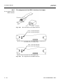
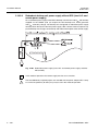
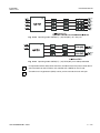
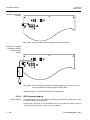
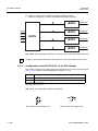
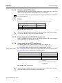
2.3.6
Subrack cascading
A maximum of four subracks can be cascaded. When they are cascaded, only one Operating and Maintenance Interface unit (OMI/OMI SNMP) may be used. The termination
units can be used as required.
i
You will not find an "In/Out" designation on the subrack for the RBus connections since
both connectors are wired in parallel. The designation "In/Out" is only used in Fig. 2.13
to indicate a possible wiring scheme for the subracks.
Fig. 2.13
2 – 16
Cascading the subrack
A3118-X300-M100-1-76D1
Installation
ULAF+ V4.2
Installation Manual
i
In order to be able to cascade subracks equipped with QSTUs, the QSTUs must have
Firmware-ID 3.49 at least.
Each subrack needs a unique address. You define the address by setting the DIP
switches on the backplane of the subrack, see Fig. 2.9 and Tab. 2.7.
The OMI bus on the last subrack must be terminated when the subracks are cascaded.
The termination is set using the DIP switches on the backplane, see Fig. 2.10 and
Tab. 2.7.
i
The overall length of the up to three cascading cables may not exceed 20 m.
A3118-X300-M100-1-76D1
2 – 17
Installation Manual
Installation
ULAF+ V4.2
2.4
Application of the OMI
i
Operating and Maintenance Interface OMI
The Operating and Maintenance Interface unit (OMI) is the link between the termination
units (xTU) and the LCT or AccessIntegrator. One OMI can administer up to 64 termination units in four subracks.
The OMI must always be inserted into slot 0 in the subrack. Should the subracks be cascaded, only one OMI may be used.
Fig. 2.14
2 – 18
Operating and Maintenance Interface unit (OMI)
A3118-X300-M100-1-76D1
Installation
ULAF+ V4.2
Installation Manual
2.4.1
Pin assignment of the connectors
The connections for the LCT or AccessIntegrator are on the front of the OMI. The two
connections take the form of RJ45 connectors. Tab. 2.12 explains the pin assignment
of these interfaces. The complete configuration cable can be ordered under the number
C195-A336-A2.
Fig. 2.15
Pin
Name
Description
3
RXD_LI
Receive signal
4
TXD_LI
Transmit signal
5
GND_LI
Ground connection
Tab. 2.12
i
RJ45 connector of the OMI for the LCT or AccessIntegrator
RS232 interface for the LCT and the AccessIntegrator (OMI)
The pins 1, 2, 6, 7 and 8 must not be connected.
An adapter cable is available for connecting the LCT interface to the RS232 interface of
your PC.
The transmission rate is 9600 baud. The data format of the interface is as follows:
• 8 data bits
• 1 start bit
• 1 stop bit
• No parity
• No handshake
A3118-X300-M100-1-76D1
2 – 19
Installation Manual
2.4.2
Installation
ULAF+ V4.2
Supervision and alarm signalling of the OMI
There are four LEDs on the front panel of the OMI for indicating the status, see
Fig. 2.16.
Fig. 2.16
Visual signalling of the OMI
Indication (LED)
Description
Green
PWR
Power on
Red
UA
Urgent alarm
Red
NU
Non-urgent alarm
Yellow
ACK
Acknowledged alarm
Tab. 2.13
Alarm acknowledgment
Description
Visual signalling of the OMI
It is possible to suppress an alarm (urgent/non-urgent) with the alarm acknowledgment
button (ACK) on the front of the OMI. An alarm acknowledged in this way is indicated by
a yellow LED on the OMI. The LED of the urgent or non-urgent alarm is canceled and
the alarm output of the corresponding plug-in unit blocked.
If a new alarm occurs after you have clicked on the alarm acknowledgment button, the
‘urgent alarm (UA)’ or ‘non-urgent alarm (ND)’ LED is reactivated. After the acknowledged alarms have disappeared, the yellow LED goes out.
2 – 20
A3118-X300-M100-1-76D1
Installation
ULAF+ V4.2
Installation Manual
2.5
Application
i
Operating and Maintenance Interface OMI SNMP
The Operating and Maintenance Interface unit OMI SNMP is the link between the transmission modules and the LCT or AccessIntegrator. One OMI SNMP can administer up
to 64 transmission modules in 4 subracks.
The OMI SNMP must always be inserted into slot 0 in the subrack. Should the subracks
be cascaded, only one OMI SNMP may be used.
Fig. 2.17
A3118-X300-M100-1-76D1
Operating and Maintenance Interface OMI SNMP
2 – 21
Installation Manual
Installation
ULAF+ V4.2
2.5.1
Pin assignment of the connectors
Fig. 2.18
Pin
RJ45 connector of the OMI SNMP
Name
3
RxD
Receive signal
4
TxD
Transmit signal
5
GND
Ground connection
Tab. 2.14
i
Description
RS232 interface for the LCT
The pins 1, 2, 6, 7 and 8 must not be connected.
An adapter cable is available for connecting the LCT interface to the RS232 interface of
your PC.
The transmission rate is 9600 baud. The data format of the interface is as follows:
• 8 data bits
• 1 start bit
• 1 stop bit
• No parity
• No handshake
Pin
Name
1
TxD+
Transmit signal
2
TxD-
Transmit signal
3
RxD+
Receive signal
4
GND
Ground connection
5
Not assigned
6
RxD-
7
Not assigned
8
Not assigned
Tab. 2.15
2 – 22
Description
Receive signal
10Base-T interface for the AccessIntegrator
A3118-X300-M100-1-76D1
Installation
ULAF+ V4.2
Installation Manual
2.5.2
Supervision and alarm signalling of the OMI SNMP
There are four LEDs on the front panel for indicating the status (Fig. 2.19).
Fig. 2.19
Indication (LED)
Description
Green
PWR
Red
UA
Urgent alarm
Red
NU
Non-urgent alarm
Yellow
ACK
Tab. 2.16
Alarm acknowledgment
Visual signalling of the OMI SNMP
Description
Power on
Acknowledged alarm
Visual signalling of the OMI SNMP
It is possible to acknowledge an alarm (urgent/non-urgent) with the alarm acknowledgment button (ACK) on the front panel of the OMI SNMP. An alarm acknowledged in this
way is indicated by a yellow LED on the OMI SNMP. The LED of the urgent or non-urgent alarm is canceled and the alarm output of the corresponding plug-in unit blocked.
If a new alarm occurs after you have clicked on the alarm acknowledgment button, the
‘urgent alarm (UA)’ or ‘non-urgent alarm (ND)’ LED is reactivated. After the acknowledged alarms have disappeared, the yellow LED goes out.
A3118-X300-M100-1-76D1
2 – 23
Installation Manual
2.5.3
Installation
ULAF+ V4.2
Inband Management with OMI SNMP
If a site does not provide facilities for connecting a ULAF+ device directly to the Management DCN of AccessIntegrator, you can use the GTU to help transfer the management data over one or several free timeslots of a 2 Mbit/s transmission link.
Fig. 2.20 shows a typical application of the GTU as Inband Management for AccessIntegrator.
For this application the GTU’s must be equipped with an Ethernet interface
(chapter 2.19.3.6) which is configured for ‘Half Duplex’ mode (Tab. 2.160).
Fig. 2.20
2 – 24
Inband Management with OMI SNMP
A3118-X300-M100-1-76D1
Installation
ULAF+ V4.2
Installation Manual
2.6
Application
HTU termination unit
The HTU termination unit can be used as a plug-in unit or as a desktop unit. This chapter
describes which settings are to be made for the HTU. The interface modules are described in chapter 2.19.
Slot 1
Slot 2
Slot 3
Slot 4
Fig. 2.21
A3118-X300-M100-1-76D1
HTU motherboard
2 – 25
Installation Manual
Installation
ULAF+ V4.2
2.6.1
Configuration of the HTU via the DIP switches
Tab. 2.21 shows the possible settings of the DIP switches (G) on the HTU.
DIP switch
1
Setting
Description
mode1)
On
NT
Off
LT mode2)
On
Module for data interface in DTE mode
Off
Module for data interface in DCE mode 1)2)
On
Configuration via the DIP switches
Off
Configuration via the LCT/AccessIntegrator 1)2)
4 3)
On
Structured mode
5 3)
Off
4 3)
Off
5
3)
Off
4
3)
Off
5 3)
On
6 3)
On
AIS recognition activated
Off
AIS recognition deactivated1)2)
On
AIS insertion1)2)
Off
AIS insertion deactivated
On
External clock-in activated
Off
Clock-in deactivated1)2)
On
Remote power supply activated
Off
Remote power supply deactivated1)2)
On
Customization activated
Off
Customization deactivated 1)2)
2
3
7 3)
8
3)
9 3)
10 3)
Transparent mode1)2)
ISDN-PRA mode
1) Default setting, desktop unit
2) Default setting, plug-in unit
3) Only operable if DIP switch 3 is ‘ON’
Tab. 2.17
i
2 – 26
Configuration of the HTU using the DIP switches
To connect ULAF-2 units to the ULAF+, the NTA-2.C and the LT/NT-2.C must have firmware version 6.4.1 or higher. If not, the firmware may need to be updated.
A3118-X300-M100-1-76D1
Installation
ULAF+ V4.2
Installation Manual
2.6.1.1
HTU with G.703 interface “onboard”
This version of the HTU is fixedly equipped with a G.703 interface (RJ45 / 120 Ω). Slot
3 (Fig. 2.21) is not applicable.
Below you will find the Pin assignment (Tab. 2.18) and the configuration of the DIP
switches for the RJ45 connector (2 Mbit/s) (Tab. 2.19).
Pin
Signal name
Description
1
G703_TXA
Transmit data
2
G703_TXB
Transmit data
3
Shield(T)
Ground connection for Tx line shield 1)
4
G703_RXA
Receive data
5
G703_RXB
Receive data
6
Shield(R)
Ground connection for Rx line shield 1)
7
Not assigned
8
Not assigned
Shield
Shield
RJ45 connector shield
1)
1) See Tab. 2.19
Tab. 2.18
Pin assignment of the RJ45 connector (2 Mbit/s)
Fig. 2.22
DIP switches for the RJ45 connector (2 Mbit/s) of the HTU
G.703
HDSL
Switch
1
Description
2
3
4
OFF
OFF
X
X
Shield (RJ45) not connected to the ground
1)
OFF
X
X
Shield (RJ45) connected via capacitor to the ground
X
Shield (RJ45) connected to the ground
X
Tx shield not connected to the ground
ON
ON
ON
1)
X
1)
X
X
ON
X
X
OFF
X
Tx shield connected via capacitor to the ground
1)
X
X
X
ON
X
X
X
OFF
Rx shield connected to the ground
Rx shield connected via capacitor to the ground
1) Default settings
Tab. 2.19
A3118-X300-M100-1-76D1
Configuration of the RJ45 connector (2 Mbit/s)
2 – 27
Installation Manual
Installation
ULAF+ V4.2
2.6.2
Power supply to the HTU
Power supply to the
plug-in unit
Power is supplied to the plug-in unit via the subrack backplane. The input voltage is
nominal 48 VDC or 60 VDC (valid range 40 - 72 VDC).
Power supply to the
desktop unit
The following options are available for power supply to the desktop unit:
• Local power supply with 110 VAC or 230 VAC (valid range 95 – 260 VAC)
• Local power supply with 48 VDC or 60 VDC (valid range 40 – 72 VDC)
• Remotely fed via HDSL interface
• Redundant power feeding (Local power supply and remotely fed)
Tab. 2.20 shows you the various power supply modes and the required power adapters
therefore:
without RPS
Desktop
with RPS
without RPS
Plug-in
Local power supply with 110 / 230 VAC
–
–
X
SNP-A03T-S
Local power supply with 48 / 60 VDC
X
X
X
X
–
1)
–
–
–
NTU
–
–
–
LT25W
LT25W
Remotely fed via HDSL interface
Redundant power feeding (local power supply
X
1)
with RPS
Power supply modes
AC and remotely fed)
Redundant power feeding (local power supply
AC and DC)
1)
Power via remote device
X
Direct power supply without power
adapter required
SNP-A03T-S
LT25W
Power adapter SNP-A03T-S
Power adapter LT25W required
NTU Power adapter NTU required
–
Tab. 2.20
Not possible
Power supply modes
You use jumpers to select the type of supply, see chapter 2.6.4. Fig. 2.23 shows the
terminals to which the supply cables are assigned.
!
Converting from AC
to DC supply
Modifications to the type of supply and grounding may only be made by trained personnel.
You can convert the desktop unit from AC to DC supply. To do this you must remove the
power cord connector and reset the jumpers as detailed in chapter 2.6.4:
1.
2.
3.
4.
5.
Disconnect the power cord and also disconnect all interface cables
Release the screws on the bottom of the unit
Open the casing by removing the top of the unit
Change the jumpers as detailed in chapter 2.6.4
Remove the power cord connector or replace the existing power cord with a new
battery cable
6. Screw the screws on the bottom of the unit into the casing
2 – 28
A3118-X300-M100-1-76D1
Installation
ULAF+ V4.2
Installation Manual
7. Screw the screws on the bottom of the unit into the casing
!
Converting from local
supply to remotely fed
Modules that are configured for DC supply may never be connected to a 230 VAC supply
directly.
For converting the desktop unit from local supply to remotely fed proceed as follows:
1.
2.
3.
4.
5.
6.
7.
8.
9.
Disconnect the power cord and also disconnect all interface cables
Interrupt the HDSL link
Release the screws on the bottom of the unit
Open the casing by removing the top of the unit
Take the module out of the casing and lay the pc board on flat surface
Remove the power cord (Warning: You must not bend the board)
Change the jumpers as detailed in chapter 2.6.4
Before closing an older casing, ensure that the two board clamps are inserted
Screw the screws on the bottom of the unit into the casing
Fig. 2.23
A3118-X300-M100-1-76D1
Terminal block (A) for the supply via the cable
2 – 29
Installation Manual
Installation
ULAF+ V4.2
The cable for external grounding is connected to terminal block A and fed out through
the cable feed-through hole (Fig. 2.24). The connection is made in the same way as the
connection for the power supply described above.
The cable for external grounding can be ordered in connectorized form.
External connecting cable ground
connection
Fig. 2.24
!
2.6.3
External grounding of desktop unit
If remote power supply > 120 V is applied, grounding is mandatory due to safety reasons. In this application the battery feeding must be grounded too.
Power modes of HTU needing external power adapter
Following desktop configurations require an external power adapter for local power
feeding with 230 VAC:
• HTU desktop equipped with an RPS module
• HTU desktop, remotely fed and redundant power feeding with local AC power
• HTU desktop, local AC power feeding and redundant power feeding with local DC
power
This chapter explains the different applications and procedures for connecting the power
adapters to the desktop units.
Desktop power
adapter SNP-A03T-S
HTU desktops equipped with an RPS module have to be powered by DC. If 230 VAC
powering is needed, the power adapter SNP-A03T-S has to be used, which generates
48 VDC on the far side.
It is also possible to use a backup battery for redundant power feeding of the LT25W.
Therefore the power adapter has to be modified as described in section “Redundant battery connection LT25W“ (Fig. 2.27).
!
Connecting desktop
power adapter
SNP-A03T-S
2 – 30
Before you open the desktop device you must interrupt the power feed and also disconnect the interface connector. The following settings must only be carried out by trained
personnel.
For connecting desktop power adapter SNP-A03T-S, proceed as follows:
1.
2.
3.
4.
5.
6.
7.
Interrupt the power supply at the desktop unit
Release the screws on the bottom of the unit
Open the casing by removing the top of the unit
Take the module out of the casing and lay the pc board on a flat surface
Remove the power cable (Warning: You must not bend the board)
Set the jumpers according to Chapter 2.6.3, Fig. 2.31 to battery supply (48 VDC)
Connect the desktop power adapter according to Fig. 2.25 (Warning: You must not
bend the board)
A3118-X300-M100-1-76D1
Installation
ULAF+ V4.2
Installation Manual
8.
9.
10.
11.
Insert the module into the casing
Route the cable through the feed-through hole on the back of the unit
Before closing an older casing, ensure that the two board clamps are inserted
Screw the screws on the bottom of the unit into the casing
Fig. 2.25
A3118-X300-M100-1-76D1
Connecting desktop power adapter SNP-A03T-S
2 – 31
Installation Manual
Redundant battery
connection LT25W
Installation
ULAF+ V4.2
In order to provide desktop power adapter LT25W with an additional battery supply you
must open the LT25W and connect a second cable. Proceed as follows:
1.
2.
3.
4.
5.
Disconnect the net cable and also disconnect all interface cables
Open the power adapter by releasing the four screws on the bottom of the unit
Remove the bottom of the casing of the power adapter
Connect the supplied cable to the terminal (1) as shown in Fig. 2.26
Replace the cable feed-through (2) (Fig. 2.26) for a cable with the one supplied for
two cables
Fig. 2.26
Connecting the battery cable to desktop power adapter LT25W
6. Close the power adapter and screw the four screws into the casing
7. Connect the power adapter to the desktop unit as described above in 2 to 11
8. Connect the battery (Fig. 2.27)
Fig. 2.27
2 – 32
Connecting the battery to desktop power adapter LT25W
A3118-X300-M100-1-76D1
Installation
ULAF+ V4.2
Installation Manual
Desktop power
adapter NTU
!
For redundant power feeding of an HTU desktop by local 110 / 230 VAC and remote
power the adapter NTU has to be used, which generates 120 VAC on the far side. Desktop configured for this application will normally take the power from the local source. If
this fails the desktop will switch automatically to remote power.
Before you open the desktop device you must interrupt the power feed and also disconnect the interface connector. The following settings must only be carried out by trained
personnel.
Fig. 2.28
Connecting desktop
power adapter NTU
Connecting desktop power adapter NTU
For connecting desktop power adapter NTU, proceed as follows:
1.
2.
3.
4.
5.
6.
7.
8.
9.
10.
11.
A3118-X300-M100-1-76D1
Interrupt the power supply at the desktop unit
Release the screws on the bottom of the unit
Open the casing by removing the top of the unit
Take the module out of the casing and lay the pc board on a flat surface
Remove the power cable (Warning: You must not bend the board)
Set the jumpers according to Chapter 2.6.4, Fig. 2.32 to remote supply (additional
jumpers are included with desktop unit NTU)
Connect the desktop power adapter according to Fig. 2.25 (Warning: You must not
bend the board)
Insert the module into the casing
Route the cable through the feed-through hole on the back of the unit
Before closing an older casing, ensure that the two board clamps are inserted
Screw the screws on the bottom of the unit into the casing
2 – 33
Installation Manual
Installation
ULAF+ V4.2
2.6.4
Set the HTU power supply via jumpers
Below, you will find the individual jumper settings for the HTUs. The following types of
use are described
• HTU used as a desktop unit
– Local AC supply
– Local DC supply; without RPS
– Local DC supply; with RPS
– Remote supply
• Use as a plug-in unit
– Local DC supply; without RPS
– Local DC supply; with RPS
The casing must be opened to change the jumper settings on the desktop unit. For this,
the screws on the bottom of the unit must be released.
!
!
Before you open the desktop device you must interrupt the power feed and also disconnect the interface connector. The following settings must only be carried out by trained
personnel.
The jumper settings for plug-in unit and desktop units are different. An HTU which is
configured as a plug-in unit may not be used with the same settings as the desktop unit.
Likewise an HTU with its jumpers set for use as a desktop unit must be reconfigured
before being used as a plug-in unit.
Only the drawn in jumpers may be set. Other combinations are not allowed and can lead
to danger to the installer or the user (electric shock or fire).
Jumper
B
Select the supply
C
Select the activation mode
D
Select the voltage range
E
Select the power-fail alarm mode
F
Select the HDSL-side supply
Tab. 2.21
2 – 34
Meaning
Meaning of jumpers B, C, D, E, F on the HTU
A3118-X300-M100-1-76D1
Installation
ULAF+ V4.2
Installation Manual
Desktop unit local
supply; AC
Fig. 2.29
Jumper settings: HTU Desktop unit local supply; AC
Fig. 2.30
Jumper settings: HTU Desktop unit, local supply; DC; without RPS
Desktop unit, local
supply; DC; without
RPS
A3118-X300-M100-1-76D1
2 – 35
Installation Manual
Installation
ULAF+ V4.2
Desktop unit, local
supply; DC; with RPS;
with desktop power
adapter SNP-A03T-S
Fig. 2.31
!
Jumper settings: HTU desktop unit, local supply; DC; with RPS;
with desktop power adapter SNP-A03T-S
For a DC supply > 60 VDC with RPS, the HTU must be grounded.
Desktop unit supplied
remotely
Fig. 2.32
!
2 – 36
Jumper settings: HTU desktop unit supplied remotely
For a remote power supply > 120 VDC, the HTU must be grounded.
A3118-X300-M100-1-76D1
Installation
ULAF+ V4.2
Installation Manual
Desktop unit supplied
redundantly with
desktop power
adapter NTU
Fig. 2.33
HTU desktop unit supplied redundantly with desktop power adapter NTU
Fig. 2.34
Jumper settings: HTU plug-in unit with and without RPS
Plug-in unit
A3118-X300-M100-1-76D1
2 – 37
Installation Manual
2.6.5
Installation
ULAF+ V4.2
Pin assignment of the HDSL interface via Jumper
Pin assignment of the
HDSL interface
Fig. 2.35
RJ45 connector of the HDSL interface
Pin 1, 2 on one wire pair
Pin 3, 4 on one wire pair
(Default settings: S3118-K301-A210; S3118-K301-B210; S3118-Q301-A310;
S3118-Q301-B210; S3118-Q301-B220)
Pin 1, 2 on one wire pair
Pin 4, 5 on one wire pair
(Default settings: S3118-K301-A110; S3118-Q301-A110)
Fig. 2.36
2 – 38
Pin assignment of the HDSL interface
A3118-X300-M100-1-76D1
Installation
ULAF+ V4.2
Installation Manual
2.6.6
Conversion of the HTU: plug-in unit - Desktop unit and
Desktop unit - plug-in unit
This chapter describes the conversion of a plug-in unit to a desktop unit, or of a desktop
unit to a plug-in unit.
!
!
Conversion of plug-in
unit → desktop unit
The conversion of the HTU from a plug-in unit to a desktop unit may only be made by
trained personnel.
The jumper settings for the plug-in units are not identical to those of the desktop units.
When a plug-in unit is converted to a desktop unit the jumpers must be set correctly.
Only the drawn in jumpers may be set. Other combinations are not allowed and can lead
to danger to the installer or the user (electric shock or fire).
Proceed as follows when converting a plug-in unit to a desktop unit:
1. Undo the screws on the front of the plug-in unit and pull it out of the subrack
2. Undo the screws on the back of the motherboard to allow the front panel to be removed
3. Lay the module on a flat surface
4. Pull off the two optical waveguide blocks
5. Insert the optical waveguides on the “Desktop side” into the module, see Fig. 2.37
and supplement the waveguides with a third block
6. Make a hole for the required submodules openings in the back of the housing at the
nominal break point
7. Set the jumpers and the DIP switches according to chapter 2.5.1 and 2.6.4 respectively
8. For the local power supply, the cable must be connected according to chapter 2.6.4
(Warning: You must not bend the board)
9. Insert the required submodules into the corresponding slots and secure these with
the safety bolt
10. Insert the motherboard into the casing (note the front-/backside!)
11. Before closing an older casing, ensure that the two board clamps are inserted.
12. Close the unit and screw the screws into the bottom of casing
A3118-X300-M100-1-76D1
2 – 39
Installation Manual
Installation
ULAF+ V4.2
Front of the plug-in unit
Board clamps
Front of the desktop unit
Fig. 2.37
!
Conversion of desktop unit → plug-in unit
2 – 40
Conversion plug-in unit → desktop unit
The jumper settings for the desktop units are not identical to those of the plug-in units.
When a desktop unit is converted to a plug-in unit the jumpers must be set correctly.
Only the drawn in jumpers may be set. Other combinations are not allowed and can lead
to danger to the installer or the user (electric shock or fire).
Proceed as follows when converting a desktop unit to a plug-in unit:
1.
2.
3.
4.
5.
Interrupt the power supply at the desktop unit
Open the casing by removing the screws on the underside
Take the module out of the casing and lay the pc board on a flat surface
Remove the power cable (Warning: You must not bend the board)
Remove the optical waveguides and reinsert two groups on the front of the plug-in
unit, see Fig. 2.37
6. Install the front panel on the front of the plug-in unit, see Fig. 2.37
7. Set the jumpers and the DIP switches according to chapter 2.6.4
8. Insert the plug-in unit into the location provided in the ULAF+ subrack (slot 1...16)
A3118-X300-M100-1-76D1
Installation
ULAF+ V4.2
Installation Manual
2.6.7
Supervision and alarm signalling of the HTU
The operating mode and alarm signalling of the HTU are indicated by means of LEDs
on the front of the unit.
2.6.7.1
Visual signalling of the plug-in unit
When the HTU is used as a plug-in unit, the front panel is equipped with six LEDs, see
Fig. 2.38.
Fig. 2.38
Visual signalling of the HTU plug-in unit
Status
LED
Color
PWR
Off
On
green
no power supply
power supply ok
red
no alarm
loss of signal/loss of frame alignment at T/V
red
no alarm
loss of signal/loss of frame alignment at U
AIS-U
yellow
no alarm
AIS at U
E6-U
yellow
no alarm
block error rate >10-6 at U
MAINT
yellow
no maintenance function
local maintenance function active
LOS/LFA-T/V
LOS/LFA-U
1)
1)
1) Visual signalling according to Fig. 2.39
Tab. 2.22
A3118-X300-M100-1-76D1
Visual signalling of HTU plug-in unit
2 – 41
Installation Manual
Installation
ULAF+ V4.2
1 Sec.
LOS - Wire pair 1
On
Off
1 Sec.
200 mS
LOS - Wire pair 2
On
Off
200 mS
LOS - Wire pair 1 + 2
400 mS
400 mS
On
Off
200 mS
On
LFA - Wire pair 1 + 2
Off
200 mS
Fig. 2.39
2.6.7.2
Visual signalling LOS/LFA
Visual signalling of the desktop unit
In contrast to the plug-in unit, the desktop unit has three additional LEDs. The meaning
of the LEDs is explained in Tab. 2.23.
Fig. 2.40
Visual signalling of the desktop unit
Status
LED
Color
LOA-Rx
yellow
Off
no permanent 0 or 1
On
permanent 0 or 1
(data interface; line 104/receive data)
LOA-Tx
yellow
no permanent 0 or 1
permanent 0 or 1
(data interface; line 103/transmit data)
LOS/LFA-T/V 1)
red
no alarm
loss of signal/loss of frame alignment at T/V
LOS/LFA-U 1)
red
no alarm
loss of signal/loss of frame alignment at U
AIS-U
yellow
no alarm
AIS at U
E6-U
yellow
no alarm
block error rate >10-6 at U
MAINT
yellow
no maintenance function
local maintenance function active
PRA
green
no ISDN-PRA operation
PRA operation
PWR
green
no power supply
power supply ok
1) Visual signalling according to Fig. 2.39
Tab. 2.23
2 – 42
Visual signalling of the desktop unit
A3118-X300-M100-1-76D1
Installation
ULAF+ V4.2
Installation Manual
2.6.8
Fault location by inserting loopbacks
By inserting loopbacks, the path can be checked for possible transmission errors. Once
the loopbacks have been inserted, the data must be returned error-free.
Loopbacks can either be inserted
• using software via the LCT/AccessIntegrator or
• using DIP switches on the modules or
• using control lines 140/141 (V.35/V36).
The procedure for inserting loopbacks by means of management software can be found
in the user manual of ULAF+ [2] or AccessIntegrator [6].
The various loopbacks are shown in Fig. 2.41 to Fig. 2.44. The names of the individual
loopbacks are explained in Tab. 2.24.
Loopback 2b can be inserted locally at the NT or remotely at the LT (loopback 2bR) using DIP-switches.
Loopback
Meaning/effect
Loopback 1
U-interface - direction V-interface (LT)
Loopback 1A
Regenerator Loopback - U-interface direction
Loopback 2b 1)
Loopback 2bR
U-interface direction - local - in the digital unit
1)
U-interface direction - remote - in the digital unit
Loopback 3a 1)
DTE1/DTE2-interface direction - in the termination unit
Loopback 3c
DTE2-interface direction - at the subscriber interface
1) Loopbacks are transparent
Tab. 2.24
A3118-X300-M100-1-76D1
Designation of the loopbacks on the HTU
2 – 43
Installation Manual
2 – 44
Installation
ULAF+ V4.2
Fig. 2.41
“Access Network’ loopback concept
Fig. 2.42
‘Campus Network’ loopback concept
Fig. 2.43
Regenerator loopback
Fig. 2.44
Loopback via control line 140/141 (V.35/V.36)
A3118-X300-M100-1-76D1
Installation
ULAF+ V4.2
Installation Manual
Notes
• The regenerator loopback can be inserted only from the LT via the LCT
• The loopback 2bR can be inserted only from the LT in the NT
• In the add-drop mode, loopback 2b is set for the two interfaces (G.703 and data) and
loopback 3c for the data interface only
• In the ‘Fractional Installation’ and ‘Partial Operation’ modes, only the loopback in the
regenerator of the active path can be set
The following loopbacks can be applied to the plug-in unit using DIP switches:
• Loopback 1 or 3a respectively
• Loopback 2bR
The following loopbacks can also be applied to the desktop unit using DIP switches:
• Loopback 2b (in ‘add-drop mode’ for the two interfaces)
• Loopback 2bR
• Loopback 3c
• Loopback 3a
A3118-X300-M100-1-76D1
2 – 45
Installation Manual
2.7
Application
Installation
ULAF+ V4.2
STU termination unit
The STU termination unit is made as
• a plug-in unit or as
• a desktop device.
Fig. 2.45 shows the STU motherboard of the plug-in unit.
This chapter describes which settings are to be made for the STU. The interface modules are described in chapter "2.19 Interface- and submodules".
Slot 1
Slot 2
Slot 3
Fig. 2.45
2 – 46
STU motherboard
A3118-X300-M100-1-76D1
Installation
ULAF+ V4.2
Installation Manual
2.7.1
Configuration of the STU via the DIP switches
Tab. 2.25 shows the possible settings of the DIP switches (S604) on the STU.
DIP-Switch
1
Setting
Description
mode1)
On
NT
Off
LT mode2)
On
Module for data interface in DTE mode
Off
Module for data interface in DCE mode 1)2)
On
Configuration via the DIP switches/ no management/ special application
Off
Configuration via the LCT/AccessIntegrator 1)2)
4 3)
On
Structured mode
5 3)
Off
4 3)
Off
5
3)
Off
4
3)
Off
5 3)
On
4 3) 4)
On
5 3) 4)
On
6 3)
On
AIS recognition activated
Off
AIS recognition deactivated 1)2)
On
AIS insertion 1)2)
Off
AIS insertion deactivated
On
External clock-in activated
Off
Clock-In deactivated 1)2)
2
3
7 3)
8
3)
Transparent mode 1)2)
ISDN-PRA mode
Automatic bit rate activated on the NT interface
With RPS “onboard”
9
10
Without RPS “onboard”
3)
Battery supply 2) 48 / 60 VDC
On
Remote power supply activated
Off
Remote power supply deactivated 1)2)3)
Main feeding 1) 110 / 230 VAC
On
Remotely fed with 180 VDC
Not assigned
Off
Remotely fed with 120 VDC
1)2)
Not assigned
1) Default setting, Desktop unit
2) Default setting, Plug-in unit
3) Only operable if DIP switch S604-3 is ‘ON’
4) STU(NT) only
Tab. 2.25
A3118-X300-M100-1-76D1
Configuration of the STU via the DIP switches (S604)
2 – 47
Installation Manual
2.7.1.1
Installation
ULAF+ V4.2
STU with G.703 interface
This version of the STU is fixedly equipped with a G.703 interface (RJ45 / 120 Ω). Slot
3 (Fig. 2.45) is not applicable.
Below you will find the Pin assignment (Tab. 2.26) and the configuration of the DIP
switches for the RJ45 connector (2 Mbit/s) (Tab. 2.27).
Pin
Signal name
Description
1
G703_TXA
Transmit data
2
G703_TXB
Transmit data
3
Shield(T)
Ground connection for Tx line shield 1)
4
G703_RXA
Receive data
5
G703_RXB
Receive data
6
Shield(R)
Ground connection for Rx line shield 1)
7
Not assigned
8
Not assigned
Shield
RJ45 connector shield 1)
Shield
1) See Tab. 2.27
Tab. 2.26
Pin assignment of the RJ45 connector (2 Mbit/s)
Fig. 2.46
DIP switches for the RJ45 connector (2 Mbit/s) of the STU
G.703
SHDSL
Switch
1
2
3
4
X
OFF
OFF
X
Shield (RJ45) not connected to the ground 2)
X
OFF
ON
X
Shield (RJ45) connected via capacitor to the ground 2)
X
ON 1)
X
X
Shield (RJ45) connected to the ground 2)
ON 1)
X
X
X
Tx shield connected to the ground
OFF
X
X
X
Tx shield connected via capacitor to the ground
Tab. 2.27
2 – 48
Description
Configuration des RJ45 connector (2 Mbit/s)
A3118-X300-M100-1-76D1
Installation
ULAF+ V4.2
Installation Manual
Switch
Description
1
2
3
4
X
X
X
ON 1)
Rx shield connected to the ground
X
X
X
OFF
Rx shield connected via capacitor to the ground
1) Default settings
2) From board status 9, the connector (RJ45) is always grounded
Tab. 2.27
2.7.2
Configuration des RJ45 connector (2 Mbit/s)
Power supply to the STU
Power supply to the
plug-in unit
Power is supplied to the plug-in unit via the subrack backplane. The input voltage is
nominal 48 VDC or 60 VDC (valid range 40 - 72 VDC).
Power supply to the
desktop unit
The following options are available for power supply to the desktop unit:
• Local power supply with 110 VAC or 230 VAC (valid range 95 – 260 VAC)
• Local power supply with 48 VDC or 60 VDC (valid range 40 – 72 VDC)
• Remotely fed via SHDSL interface
• Redundant power feeding (Local power supply and remotely fed)
Tab. 2.28 shows you the various power supply modes and the required power adapters
therefore:
without RPS
Desktop
with RPS
without RPS
Plug-in
Local power supply with 110 / 230 VAC
–
–
X
SNP-A03T-S
Local power supply with 48 / 60 VDC
X
X
X
X
–
1)
–
–
–
NTU
–
–
–
LT25W
LT25W
Remotely fed via SHDSL interface
Redundant power feeding (local power supply
X
1)
with RPS
Power supply modes
AC and remotely fed)
Redundant power feeding (local power supply
AC and DC)
1)
Power via remote device
X
Direct power supply without power
adapter required
SNP-A03T-S
LT25W
Power adapter SNP-A03T-S
Power adapter LT25W required
NTU Power adapter NTU required
–
Tab. 2.28
Not possible
Power supply modes
You use jumpers to select the type of supply, see chapter 2.7.4. Fig. 2.47 shows the
terminals to which the supply cables are assigned.
!
Modifications to the type of supply and grounding may only be made by trained personnel.
A3118-X300-M100-1-76D1
2 – 49
Installation Manual
Installation
ULAF+ V4.2
Converting from AC
to DC supply
You can convert the desktop unit from AC to DC supply after it has been installed. To
do this you must reset the DIP switch S604-9 as detailed in chapter 2.7.1:
1.
2.
3.
4.
5.
Disconnect the power cord and also disconnect all interface cables
Release the screws on the bottom of the unit
Open the casing by removing the top of the unit
Reset the DIP switch S604-9 on ‘ON’ (Battery supply)
Remove the power cord connector or replace the existing power cord with a new
battery cable
6. Close the casing
7. Screw the screws on the bottom of the unit into the casing
!
Converting from local
supply to remotely fed
Modules that are configured for DC supply may never be connected to 110 / 230 VAC
supply directly.
For converting the desktop unit from local supply to remotely fed proceed as follows:
1.
2.
3.
4.
5.
6.
7.
8.
9.
10.
Disconnect the power cord and also disconnect all interface cables
Interrupt the SHDSL link
Release the screws on the bottom of the unit
Open the casing by removing the top of the unit
Take the module out of the casing and lay the pc board on a flat surface
Remove the power cord (Warning: You must not bend the board)
Change the jumpers as detailed in chapter 2.7.4
Reset the DIP switch S604-9 on ‘ON’ (Battery supply)
Before closing an older casing, ensure that the two board clamps are inserted
Screw the screws on the bottom of the unit into the casing
Fig. 2.47
2 – 50
Terminal block (A) for the supply via the cable
A3118-X300-M100-1-76D1
Installation
ULAF+ V4.2
Installation Manual
The cable for external grounding is connected to terminal block A and fed out through
the cable feed-through hole (Fig. 2.48). The connection is made in the same way as the
connection for the power supply described above.
The cable for external grounding can be ordered in connectorized form.
External connection cable ground
connection
Fig. 2.48
!
External grounding of desktop unit
If remote power supply > 120 VDC is applied, grounding is mandatory due to safety reasons. In this application the battery feeding must be grounded too.
2.7.2.1
STU grounding concept
Subrack
The subrack must always be grounded.
Desktop devices
!
For the following applications the STU desktop devices must be grounded over a cable
of at least 0,75 mm2:
• Desktop device receiving remote feed with a remote feed voltage of >120 VDC
→ Grounding is done over terminal (Fig. 2.47) or, if there is no other option at the
screen connector of the RJ45 SHDSL connector (Fig. 2.49)
• Desktop device supplying remote feed with remote feed voltage of >120 VDC
→ Grounding is done over terminal (Fig. 2.47)
For >120 VDC remote feed earthing is urgently required and must exist as described in
chapter 2.7.2. If there is no other chance, the desktop device remotely fed with 180 VDC
can also be earthed over the SHDSL connector (Fig. 2.49).
Fig. 2.49
A3118-X300-M100-1-76D1
Grounding of SHDSL connector
2 – 51
Installation Manual
Installation
ULAF+ V4.2
2.7.2.2
Fuses F1; F401/F403; F500
The basic modules are equipped with the following fuses (the equipping depends on using the basic modules as a plug-in unit or as a desktop device):
Type of fuse
Equipped on...
F1 - 250 V / 1,25 AT
Desktop device
F500 - 120 V / 1 AT
Plug-in unit
F403 - 120 V / 1 AT
Desktop device and plug-in unit 1)
F401
Not assigned
1) from board status 9: F403 - 250 V / 1,25 AT
Tab. 2.29
!
2.7.3
The usage of fuse types
The fuses have a protecting function and should be replaced only by fuses with exactly
the same electrical specifications. When a fuse burns, a device damage should be considered.
Power modes of STU needing external power adapter
Following desktop configurations require an external power adapter for local power
feeding with 230 VAC:
• STU desktop equipped with an RPS module
• STU desktop, remotely fed and redundant power feeding with local AC power
• STU desktop, local AC power feeding and redundant power feeding with local DC
power
This chapter explains the different applications and procedures for connecting the power
adapters to the desktop units.
Desktop power
adapter SNP-A03T-S
STU desktops equipped with an RPS module have to be powered by DC. If 110 /
230 VAC powering is needed, the power adapter SNP-A03T-S has to be used, which
generates 48 VDC on the far side.
It is also possible to use a backup battery for redundant power feeding of the LT25W.
Therefore the power adapter has to be modified as described in section “Redundant battery connection LT25W“ (Fig. 2.50).
!
Connecting desktop
power adapter
SNP-A03T-S
2 – 52
Before you open the desktop device you must interrupt the power feed and also disconnect the interface connector. The following settings must only be carried out by trained
personnel.
For connecting desktop power adapter SNP-A03T-S, proceed as follows:
1.
2.
3.
4.
5.
6.
Interrupt the power supply at the desktop unit
Release the screws on the bottom of the unit
Open the casing by removing the top of the unit
Take the module out of the casing and lay the pc board on a flat surface
Remove the power cable (Warning: You must not bend the board)
Set the jumpers according to Chapter 2.7.4, Fig. 2.54 to local feeding (48 VDC). If
you are using a desktop model without RPS you must set jumper S604-9 on “ON”.
7. Connect the desktop power adapter according to Fig. 2.50 (Warning: You must not
bend the board)
8. Insert the module into the casing
A3118-X300-M100-1-76D1
Installation
ULAF+ V4.2
Installation Manual
9. Route the cable through the feed-through hole on the back of the unit
10. Before closing an older casing, ensure that the two board clamps are inserted
11. Screw the screws on the bottom of the unit into the casing
Fig. 2.50
A3118-X300-M100-1-76D1
Connecting desktop power adapter SNP-A03T-S
2 – 53
Installation Manual
Redundant battery
connection LT25W
Installation
ULAF+ V4.2
In order to provide desktop power adapter LT25W with an additional battery supply you
must open the unit and connect a second cable. Proceed as follows:
1.
2.
3.
4.
5.
Disconnect the net cable and also disconnect all interface cables
Open the power adapter by releasing the four screws on the bottom of the unit
Remove the bottom of the casing of the power adapter
Connect the supplied cable to the terminal (1) as shown in Fig. 2.51
Replace the cable feed-through (2) (Fig. 2.51) for a cable with the one supplied for
two cables
Fig. 2.51
Connecting the battery cable to desktop power adapter LT25W
6. Close the power adapter and screw the four screws into the casing
7. Connect the power adapter to the desktop unit as described above in 2 to 11
8. Connect the battery (Fig. 2.52)
Fig. 2.52
2 – 54
Connecting the battery to desktop power adapter LT25W
A3118-X300-M100-1-76D1
Installation
ULAF+ V4.2
Installation Manual
Desktop power
adapter NTU
!
For redundant power feeding of an STU desktop by local 230 VAC and remote power the
adapter NTU has to be used, which generates 120 VAC on the far side. Desktop model
configured for this application will normally take the power from the local source. If this
fails the desktop will switch automatically to remote power.
Before you open the desktop device you must interrupt the power feed and also disconnect the interface connector. The following settings must only be carried out by trained
personnel.
Fig. 2.53
Connecting desktop
power adapter NTU
Connecting desktop power adapter NTU
For connecting desktop power adapter NTU, proceed as follows:
1.
2.
3.
4.
5.
6.
7.
8.
9.
10.
11.
A3118-X300-M100-1-76D1
Interrupt the power supply at the desktop unit
Release the screws on the bottom of the unit
Open the casing by removing the top of the unit
Take the module out of the casing and lay the pc board on a flat surface
Remove the power cable (Warning: You must not bend the board)
Set the jumpers according to Chapter 2.7.4, Fig. 2.56 to remote supply (additional
jumpers are included with desktop unit NTU)
Connect the desktop power adapter according to Fig. 2.53 (Warning: You must not
bend the board)
Insert the module into the casing
Route the cable through the feed-through hole on the back of the unit
Before closing the casing, ensure that the two board clamps are inserted
Screw the screws on the bottom of the unit into the casing
2 – 55
Installation Manual
Installation
ULAF+ V4.2
2.7.4
Set the STU power supply via jumpers
Below, you will find the individual jumper settings for the STU. The following types of use
are described:;
• STU used as a desktop unit
– Local AC supply
– Local DC supply
– Remote supply
• STU used as a plug-in unit
– Local DC supply
The casing must be opened to change the jumper settings on the desktop unit. For this,
the screws on the bottom of the unit must be released.
!
Before you open the desktop device you must interrupt the power feed and also disconnect the interface connector. The following settings must only be carried out by trained
personnel.
!
The jumper settings for plug-in unit and desktop units are different.
Only the drawn in jumpers may be set. Other combinations are not allowed and can lead
to danger to the installer or the user (electric shock or fire).
The jumper sockets B, C and D are not equipped in all models of the STU. The following
instructions only apply if the corresponding jumper sockets are equipped on the STU.
Jumper
B
Desktop unit local supply; AC or DC
C
Supply of the plug-in unit
D
Desktop unit supplied remotely
Tab. 2.30
!
2 – 56
Meaning
Meaning of jumpers B, C and D on the STU
Locally powered STU modules with activated RPS must only be supplied with DC!
A3118-X300-M100-1-76D1
Installation
ULAF+ V4.2
Installation Manual
Desktop unit local
supply; AC or DC
Fig. 2.54
A3118-X300-M100-1-76D1
Jumper settings: STU desktop unit local supply; AC or DC
2 – 57
Installation Manual
Installation
ULAF+ V4.2
Desktop unit supplied
remotely
Fig. 2.55
!
!
2 – 58
Jumper settings: STU Desktop unit supplied remotely
Locally powered STU modules with activated RPS must only be supplied with DC!
With a remote power supply that is < 120 V, grounding is mandatory and must be
present as described in chapter 2.7.2. If you have no other option, the desktop that is
supplied remotely with 180 VAC can also be grounded via the SHDSL connector.
A3118-X300-M100-1-76D1
Installation
ULAF+ V4.2
Installation Manual
Desktop unit supplied
redundantly with
desktop power adapter NTU
Fig. 2.56
2.7.5
Remote feeding
Jumper settings: Desktop unit supplied redundantly with desktop power
adapter NTU
STU remote feeding
The STU plug-in unit can be supplied with an integrated remote power supply. This enables the remote feed of a desktop device or two regenerator.
Transmission and supply is done via the SHDSL path. The ground-free supply voltage
is either 120 VDC or 180 VDC. The remote supply current is 50 mA or 60 mA.
i
Remote feed voltage
180 VDC
The remote power supply module (RPSII, chapter 2.19.5) cannot be used together with
the STU.
When using the remote feed voltage of 180 VDC the following preconditions must be
met:
• A RFT-C circuit must be involved
• The cables must be approved for a remote feed voltage of 180 VDC
• The line capacity to ground for the entire system must not exceed 14 μF.
A3118-X300-M100-1-76D1
2 – 59
Installation Manual
Installation
ULAF+ V4.2
2.7.5.1
Configuration of the DIP switches for STU remote feed
Fig. 2.57 shows you the settings for the plug-in unit to remote feed desktop device with
120 V. Fig. 2.58 shows you the settings for 180 V remote feed voltage.
i
The DIP switches ‘S604-10’ and ‘S2-1’ as well as Jumper M must be set regardless of
using the LCT.
The remote feed is turned on/off either using the DIP switch S604-9 (if DIP switch
S604-3 is “On”), see Tab. 2.25, or via the LCT (if DIP switch S604-3 is “Off”).
!
STU devices with RPS on board powered locally with 48 V / 60 VDC.
Fig. 2.57
2 – 60
STU remote feed voltage 120 V
A3118-X300-M100-1-76D1
Installation
ULAF+ V4.2
Installation Manual
Fig. 2.58
STU remote feed voltage 180 V
Set the current limit with the DIP switch 2-2:
Switch S2-2
Setting
On
50 mA
Off
60 mA
Tab. 2.31
i
Meaning
Current limit for STU remote feed
The DIP switche ‘S2-2’ must be set regardless of using the LCT.
A3118-X300-M100-1-76D1
2 – 61
Installation Manual
2.7.5.2
Installation
ULAF+ V4.2
STU remote feed monitoring and alarm signalling
Monitoring circuit
A monitoring circuit controls the voltage and the current control. The settings are done
using DIP switches, see chapter 2.7.5.1. For security reasons, two independent circuit
parts and two independent DIP switches are needed for the settings relevant to security.
Earth leakage
The output voltage is monitored for earth leakage and is turned off in case of fault. In
case of a disturbance the STU tries to reestablish the remote feed.
The STU remote feed recognizes the following states:
• Remote feeding current too deep (under current)
• Remote feeding current too high (short circuit)
• Earth leakage
Out of this states the STU generates the following alarms:
Alarm
Event
Description
Generated alarm
UCR1
Line break
Remote feeding current too deep (Under current)
Non-urgent alarm
UNBAL
Earth leakage
Protection circuit turned of because of earth leak-
Urgent alarm
age
OC
Tab. 2.32
Short circuit
Remote feeding current too high (Over current)
Urgent alarm
STU remote feed alarm signalling
You can test the protection circuit by, for example, setting the voltage control at 180 VAC
(Jumper M, DIP-Switch S604-1 “ON”) and the voltage monitoring at 120 VDC (DIPSwitch S604-10 “OFF”). In this constellation the protection circuit must respond.
2.7.5.3
Configuration of the power fail recognition using DIP switches
The configuration is done using the DIP switch S604-9, see Tab. 2.25.
2.7.6
Pin assignment of the
SHDSL interface
Pin assignment of the SHDSL interface
12345678
SHDSL line (Pin 4: b (Ring); Pin 5: a (Tip))
Fig. 2.59
2.7.7
RJ45 connector of the SHDSL interface
Supervision and alarm signalling of the STU
The operating mode and alarm signalling of the STU are indicated by means of LEDs
on the front of the unit.
2 – 62
A3118-X300-M100-1-76D1
Installation
ULAF+ V4.2
Installation Manual
2.7.7.1
Visual signalling of the plug-in unit
When the STU is used as a plug-in unit, the front panel is equipped with six LEDs
(Fig. 2.60).
Fig. 2.60
Visual signalling of the STU plug-in unit
Status
LED
Color
PWR
Off
On
green
no power supply
power supply ok
red
no alarm
loss of signal/loss of frame alignment at T/V
red
no alarm
loss of signal/loss of frame alignment at U
AIS-U
yellow
no alarm
AIS at U
E6-U
yellow
no alarm
Block error rat >10-6 at U
MAINT
yellow
no maintenance function
local maintenance function active
LOS/LFA-T/V
LOS/LFA-U
1)
1)
1) Visual signalling according to Fig. 2.61
Tab. 2.33
Visual signalling of STU plug-in unit
LOS-U
LOS-T/V
On
LFA-T/V
LFA-U
On
Off
200 mS
Off
200 mS
1 Sec.
On
BNA-U
Off
1 Sec.
Fig. 2.61
A3118-X300-M100-1-76D1
Visual signalling LOS/LFA/BNA
2 – 63
Installation Manual
2.7.7.2
Installation
ULAF+ V4.2
Visual signalling of the desktop unit
In contrast to the plug-in unit, the desktop unit has three additional LEDs. The meaning
of the LEDs is explained in Tab. 2.23.
Fig. 2.62
Visual signalling of the desktop unit
Status
LED
Color
LOA-Rx
yellow
Off
no permanent 0 or 1
On
permanent 0 or 1
(data interface; line 104/receive data)
LOA-Tx
yellow
no permanent 0 or 1
permanent 0 or 1
(data interface; line 103/transmit data)
LOS/LFA-T/V
1)
red
no alarm
loss of signal/loss of frame alignment at T/V
red
no alarm
loss of signal/loss of frame alignment at U
AIS-U
yellow
no alarm
AIS at U
E6-U
yellow
no alarm
Block error rare >10-6 at U
MAINT
yellow
no maintenance function
Local maintenance function active
PRA
green
no ISDN-PRA operation
PRA operation
PWR
green
no power supply
Power supply ok
LOS/LFA-U
1)
1) Visual signalling according to Fig. 2.61
Tab. 2.34
2.7.8
Visual signalling of the desktop unit
Fault location by inserting loopbacks
By inserting loopbacks, the path can be checked for possible transmission errors. Once
the loopbacks have been inserted, the data must be returned error-free.
Loopbacks can either be inserted
• using software via the LCT/AccessIntegrator or
• using DIP switches on the modules or
• using control lines 140/141 (V.35/V36).
The procedure for inserting loopbacks by means of management software can be found
in the user manual of ULAF+ [2] or AccessIntegrator [6].
The various loopbacks are shown in Fig. 2.41 to Fig. 2.44. The names of the individual
loopbacks are explained in Tab. 2.24.
Loopback 2b can be inserted locally at the NT or remotely at the LT (loopback 2bR) using DIP switches.
2 – 64
A3118-X300-M100-1-76D1
Installation
ULAF+ V4.2
Installation Manual
Loopback
Loopback 1
Meaning / effect
U-interface - direction V-interface (LT)
Loopback 2b
1)
Loopback 2bR 1)
Loopback 3a
Loopback 3c
1)
U-interface direction - local - in the digital unit
U-interface direction - remote - in the digital unit
DTE1/DTE2-interface direction - in the termination unit
DTE2-interface direction - at the subscriber interface
1) Loopbacks are transparent
Tab. 2.35
Designation of the loopbacks on the STU
Fig. 2.63
‘Access Network’ loopback concept
Fig. 2.64
‘Campus Network’ loopback concept
Fig. 2.65
Regenerator loopback concept
A3118-X300-M100-1-76D1
2 – 65
Installation Manual
Installation
ULAF+ V4.2
Fig. 2.66
Loopback via control line 140/141 (V.35/V.36)
Notes
• In the add-drop mode, loopback 2b is set for the two interfaces (G.703 and data) and
loopback 3c for the data interface only
• The loopback 2bR can be inserted only from the LT in the NT
The following loopbacks can be applied to the plug-in unit using DIP switches:
• Loopback 1 or 3a respectively
• Loopback 2bR
The following loopbacks can also be applied to the desktop unit using DIP switches:
• Loopback 2b (in ‘add-drop mode’ for the two interfaces)
• Loopback 2bR
• Loopback 3c
• Loopback 3a
2 – 66
A3118-X300-M100-1-76D1
Installation
ULAF+ V4.2
Installation Manual
2.8
STU termination unit with G.703 64 kbit/s (codirectional)
Termination unit STU with G.703 64 kbit/s interface (codirectional) largely corresponds
to termination unit STU with G.703 2 Mbit/s interface. This chapter describes the differences between the units in respect of the G.703 interface. For any further STU information, see chapter 2.7.
Application
The STU termination unit is made as
• a plug-in unit or as
• a desktop device.
Fig. 2.67 shows the STU motherboard of the plug-in unit.
This variant of the STU unit cannot be expanded with additional data interfaces. The
G.703 64 kbit/s codirectional interface is permanently soldered to the main board.
The desktop unit can be additionally expanded with the module for the alarm and clock
interface.
Alarm- and
Clock interface
G.703 64 kbit/s
(codirectional)
Fig. 2.67
A3118-X300-M100-1-76D1
STU (G.703 64 kbit/s) motherboard
2 – 67
Installation Manual
2.8.1
Installation
ULAF+ V4.2
Configuration of the STU via the DIP switches
Tab. 2.36 shows the possible settings of the DIP switches (S604) on the STU (G.703
64 kbit/s).
DIP-Switch
Setting
Description
On
NT mode1)
Off
LT mode2)
2
Off
Not assigned
3
On
Configuration via the DIP switches
Off
Configuration via the LCT/AccessIntegrator 1)2)
4 3)
On
Structured mode
5 3)
Off
4 3)
Off
5 3)
Off
6 3)
On
AIS recognition activated at U interface
Off
AIS recognition deactivated at U interface 1)2)
7
Off
Not assigned
8 3)
On
External clock-in activated
Off
Clock-In deactivated 1)2)
On
Battery supply 2) 48 / 60 VDC
Off
Main feeding 1) 110 / 230 VAC
Off
Not assigned
1
9
10
Transparent mode 1)2)
1) Default setting, Desktop unit
2) Default setting, Plug-in unit
3) Only operable if DIP switch S604-3 is ‘ON’
Tab. 2.36
2 – 68
Configuration of the STU (G.703 64 kbit/s) via the DIP switches (S604)
A3118-X300-M100-1-76D1
Installation
ULAF+ V4.2
Installation Manual
2.8.1.1
G.703 64 kbit/s (codirectional) interface
The G.703 64 kbit/s interface is soldered on the main board and implemented as RJ45 /
120 Ω connector.
Below you will find the Pin assignment (Tab. 2.37) and the configuration of the DIP
switches for the RJ45 connector (2 Mbit/s) (Tab. 2.38).
Pin
Signal name
Description
1
G703_TXA
Transmit data
2
G703_TXB
Transmit data
3
Shield(T)
Ground connection for Tx line shield 1)
4
G703_RXA
Receive data
5
G703_RXB
Receive data
6
Shield(R)
Ground connection for Rx line shield 1)
7
Not assigned
8
Not assigned
Shield
Shield
RJ45 connector shield
1)
1) See Tab. 2.38
Tab. 2.37
Pin assignment of the RJ45 connector (2 Mbit/s)
Fig. 2.68
DIP switches for the RJ45 connector
G.703
SHDSL
Switch
1
2
3
4
X
OFF
OFF
X
Shield (RJ45) not connected to the ground 2)
X
OFF
ON
X
Shield (RJ45) connected via capacitor to the ground 2)
X
ON 1)
ON 1)
X
Shield (RJ45) connected to the ground 2)
ON 1)
X
X
X
Tx shield not connected to the ground
OFF
X
X
X
Tx shield connected via capacitor to the ground
Tab. 2.38
A3118-X300-M100-1-76D1
Description
Configuration des RJ45 connector (2 Mbit/s)
2 – 69
Installation Manual
Installation
ULAF+ V4.2
Switch
Description
1
2
3
4
X
X
X
ON 1)
Rx shield connected to the ground
X
X
X
OFF
Rx shield connected via capacitor to the ground
1) Default settings
2) From board status 9, the the connector (RJ45) is always grounded
Tab. 2.38
2.8.2
Configuration des RJ45 connector (2 Mbit/s)
Power supply to the STU (G.703 64 kbit/s)
Power supply to the
plug-in unit
Power is supplied to the plug-in unit via the subrack backplane. The input voltage is
nominal 48 VDC or 60 VDC (valid range 40 - 72 VDC).
Power supply to the
desktop unit
The following options are available for power supply to the desktop unit:
• Local power supply with 110 VAC or 230 VAC (valid range 95 – 260 VAC)
• Local power supply with 48 VDC or 60 VDC (valid range 40 – 72 VDC)
Power supply modes
Tab. 2.39 shows you the various power supply modes and the required power adapters
therefore:
Plug-in
Desktop
Local power supply with 110 / 230 VAC
–
X
Local power supply with 48 / 60 VDC
X
X
Redundant power feeding (local power supply AC and DC)
–
LT25W
Tab. 2.39
Power supply modes
You use jumpers to select the type of supply, see chapter 2.7.4. Fig. 2.47 shows the
terminals to which the supply cables are assigned.
!
Converting from AC
to DC supply
2.8.2.1
Modifications to the type of supply and grounding may only be made by trained personnel.
You can convert the desktop unit from AC to DC supply after it has been installed. To
do this you must reset the DIP switch S604-9 as detailed in chapter 2.7.1:
STU (G.703 64 kbit/s) grounding concept)
The STU grounding concept is described in chapter 2.7.2.1.
2.8.2.2
Fuses F1; F401/F403; F500
You find more information about the fuses in chapter 2.7.2.2.
2.8.3
Power modes of STU (G.703 64 kbit/s) needing external power
adapter
Desktop units which you wish to operate locally with AC and redundantly with local DC
power require an external power supply unit (LT25W or SNP-A03T-S). For further information, see chapter 2.7.3.
2 – 70
A3118-X300-M100-1-76D1
Installation
ULAF+ V4.2
Installation Manual
2.8.4
Set the STU power supply via jumpers
The jumper settings for the STU (G.703 64 kbit/s) is described in chapter 2.7.4.
2.8.5
Pin assignment of the SHDSL interface
The pin assignmeent of the SHDSL interface is described in chapter 2.7.6.
2.8.6
Supervision and alarm signalling of the STU
The operating mode and alarm signalling of the STU (G.703 64 kbit/s) are indicated by
means of LEDs on the front of the unit.
2.8.6.1
Visual signalling of the plug-in unit
When the STU(G.703 64 kbit/s) is used as a plug-in unit, the front panel is equipped with
six LEDs (Fig. 2.69).
Fig. 2.69
Visual signalling of the STU plug-in unit
Status
LED
Color
PWR
Off
On
green
no power supply
power supply ok
red
no alarm
loss of signal at T/V
red
no alarm
loss of signal/loss of frame alignment at U
AIS-U
yellow
no alarm
AIS at U
E6-U
yellow
no alarm
Block error rat >10-6 at U
MAINT
yellow
no maintenance function
local maintenance function active
LOS-T/V
1)
LOS/LFA-U
1)
1) Visual signalling according to Fig. 2.70
Tab. 2.40
A3118-X300-M100-1-76D1
Visual signalling of STU plug-in unit
2 – 71
Installation Manual
Installation
ULAF+ V4.2
LOS-U
LOS-T/V
On
Off
On
LFA-U
200 mS
Off
200 mS
1 Sec.
On
BNA-U
Off
1 Sec.
Fig. 2.70
2.8.6.2
Visual signalling LOS/LFA/BNA
Visual signalling of the desktop unit
In contrast to the plug-in unit, the desktop unit has three additional LEDs. The meaning
of the LEDs is explained in Tab. 2.41.
Fig. 2.71
Visual signalling of the desktop unit
Status
LED
LOA-Rx
LOA-Tx
LOS-T/V
1)
Color
Off
On
yellow
always off - LED without function
yellow
always off - LED without function
red
no alarm
loss of signal at T/V
LOS/LFA-U 1)
red
no alarm
loss of signal/loss of frame alignment at U
AIS-U
yellow
no alarm
AIS at U
E6-U
yellow
no alarm
Block error rare >10-6 at U
MAINT
yellow
no maintenance function
Local maintenance function active
PRA
green
no ISDN-PRA operation
PRA operation
PWR
green
no power supply
Power supply ok
1) Visual signalling according to Fig. 2.70
Tab. 2.41
2.8.7
Visual signalling of the desktop unit
Fault location by inserting loopbacks
By inserting loopbacks, the path can be checked for possible transmission errors. Once
the loopbacks have been inserted, the data must be returned error-free. You find more
information about inserting loopbacks in chapter 2.7.8.
2 – 72
A3118-X300-M100-1-76D1
Installation
ULAF+ V4.2
Installation Manual
2.9
Application
STU2 termination unit
The STU2 termination unit is made as
• a plug-in unit or as
• a desktop device.
Fig. 2.72 shows the STU2 motherboard of the plug-in unit.
This chapter describes which settings are to be made for the STU2. The interface modules are described in chapter "2.19 Interface- and submodules".
Slot 1
Slot 2
Slot 3
Fig. 2.72
A3118-X300-M100-1-76D1
STU2 motherboard
2 – 73
Installation Manual
2.9.1
Installation
ULAF+ V4.2
Configuration of the STU2 via the DIP switches
Tab. 2.42 shows the possible settings of the DIP switches (S604) on the STU2.
DIP-Switch
1
Setting
Description
mode1)
On
NT
Off
LT mode2)
On
Module for data interface in DTE mode
Off
Module for data interface in DCE mode 1)2)
On
Configuration via the DIP switches
Off
Configuration via the LCT/AccessIntegrator 1)2)
4 3)
On
Structured mode
5 3)
Off
4 3)
Off
5
3)
Off
4
3)
Off
5 3)
On
6 3)
On
AIS recognition activated
Off
AIS recognition deactivated 1)2)
On
AIS insertion 1)2)
Off
AIS insertion deactivated
On
External clock-in activated
Off
Clock-In deactivated 1)2)
2
3
7 3)
8
3)
Transparent mode 1)2)
ISDN-PRA mode
With RPS “onboard”
9
10
Without RPS “onboard”
3)
Battery supply 2) 48 / 60 VDC
On
Remote power supply activated
Off
Remote power supply deactivated 1)2)3)
Main feeding 1) 110 / 230 VAC
On
Remotely fed with 180 VDC
Not assigned
Off
Remotely fed with 120 VDC
1)2)
Not assigned
1) Default setting, Desktop unit
2) Default setting, Plug-in unit
3) Only operable if DIP switch S604-3 is ‘ON’
Tab. 2.42
2 – 74
Configuration of the STU2 via the DIP switches (S604)
A3118-X300-M100-1-76D1
Installation
ULAF+ V4.2
Installation Manual
2.9.2
Power supply to the STU2
Power supply to the
plug-in unit
Power is supplied to the plug-in unit via the subrack backplane. The input voltage is
nominal 48 VDC or 60 VDC (valid range 40 - 72 VDC).
Power supply to the
desktop unit
The following options are available for power supply to the desktop unit:
• Local power supply with 110 VAC or 230 VAC (valid range 95 – 260 VAC)
• Local power supply with 48 VDC or 60 VDC (valid range 40 – 72 VDC)
• Remotely fed via SHDSL interface
• Redundant power feeding (Local power supply and remotely fed)
Power supply modes
Tab. 2.43 shows you the various power supply modes and the required power adapters
therefore:
without RPS
with RPS
Desktop
with RPS
without RPS
Plug-in
Local power supply with 110 / 230 VAC
–
–
X
SNP-A03T-S
Local power supply with 48 / 60 VDC
X
X
X
X
–
1)
–
–
–
NTU
–
–
–
LT25W
LT25W
Remotely fed via SHDSL interface
Redundant power feeding (local power supply
X
1)
AC and remotely fed)
Redundant power feeding (local power supply
AC and DC)
1)
Power via remote device
X
Direct power supply without power
adapter required
SNP-A03T-S
LT25W
Power adapter SNP-A03T-S
Power adapter LT25W required
NTU Power adapter NTU required
–
Tab. 2.43
Not possible
Power supply modes
You use jumpers to select the type of supply, see chapter 2.9.4. Fig. 2.73 shows the
terminals to which the supply cables are assigned.
!
Converting from AC
to DC supply
Modifications to the type of supply and grounding may only be made by trained personnel.
You can convert the desktop unit from AC to DC supply after it has been installed. To
do this you must reset the DIP switch S604-9 as detailed in chapter 2.9.1:
1.
2.
3.
4.
5.
Disconnect the power cord and also disconnect all interface cables
Release the screws on the bottom of the unit
Open the casing by removing the top of the unit
Reset the DIP switch S604-9 on ‘ON’ (Battery supply)
Remove the power cord connector or replace the existing power cord with a new
battery cable
6. Close the casing
A3118-X300-M100-1-76D1
2 – 75
Installation Manual
Installation
ULAF+ V4.2
7. Screw the screws on the bottom of the unit into the casing
!
Converting from local
supply to remotely fed
Modules that are configured for DC supply may never be connected to 110 / 230 VAC
supply directly.
For converting the desktop unit from local supply to remotely fed proceed as follows:
1.
2.
3.
4.
5.
6.
7.
8.
9.
10.
Disconnect the power cord and also disconnect all interface cables
Interrupt the SHDSL link
Release the screws on the bottom of the unit
Open the casing by removing the top of the unit
Take the module out of the casing and lay the pc board on a flat surface
Remove the power cord (Warning: You must not bend the board)
Change the jumpers as detailed in chapter 2.9.4
Reset the DIP switch S604-9 on ‘ON’ (Battery supply)
Before closing an older casing, ensure that the two board clamps are inserted
Screw the screws on the bottom of the unit into the casing
Fig. 2.73
Terminal block (A) for the supply via the cable
The cable for external grounding is connected to terminal block A and fed out through
the cable feed-through hole (Fig. 2.74). The connection is made in the same way as the
connection for the power supply described above.
2 – 76
A3118-X300-M100-1-76D1
Installation
ULAF+ V4.2
Installation Manual
The cable for external grounding can be ordered in connectorized form.
External connection cable ground
connection
Fig. 2.74
!
External grounding of desktop unit
If remote power supply > 120 V is applied, grounding is mandatory due to safety reasons.
2.9.2.1
STU2 grounding concept
Subrack
The subrack must always be grounded.
Desktop devices
!
For the following applications the STU2 desktop devices must be grounded over a cable
of at least 0,75 mm2:
• Desktop device receiving remote feed with a remote feed voltage of >120 VDC
→ Grounding is done over terminal (Fig. 2.73) or, if there is no other option at the
screen connector of the RJ45 SHDSL connector (Fig. 2.75)
• Desktop device supplying remote feed with remote feed voltage of >120 VDC
→ Grounding is done over terminal (Fig. 2.73)
For >120 VDC remote feed earthing is urgently required and must exist as described in
chapter 2.9.2. If there is no other chance, the desktop device remotely fed with 180 V
can also be earthed over the SHDSL connector (Fig. 2.75).
Fig. 2.75
A3118-X300-M100-1-76D1
Grounding of SHDSL connector
2 – 77
Installation Manual
Installation
ULAF+ V4.2
2.9.2.2
Fuses F1; F401/F403; F500
The basic modules are equipped with the following fuses (the equipping depends on using the basic modules as a plug-in unit or as a desktop device):
Type of fuse
F1 - 250 V / 1,25 AT
Desktop device
F500 - 120 V / 1 AT
Plug-in unit
F401/501 - 120 V / 1 AT
Desktop device and plug-in unit
Tab. 2.44
!
2.9.3
Equipped on...
The usage of fuse types
The fuses have a protecting function and should be replaced only by fuses with exactly
the same electrical specifications. When a fuse burns, a device damage should be considered.
Power modes of STU2 needing external power adapter
Following desktop configurations require an external power adapter for local power
feeding with 230 VAC:
• STU2 desktop equipped with an RPS module
• STU2 desktop, remotely fed and redundant power feeding with local AC power
• STU2 desktop, local AC power feeding and redundant power feeding with local DC
power
This chapter explains the different applications and procedures for connecting the power
adapters to the desktop units.
Desktop power adapter SNP-A03T-S
STU2 desktops equipped with an RPS module have to be powered by DC. If 110 V /
230 VAC powering is needed, the power adapter SNP-A03T-S has to be used, which
generates 48 VDC on the far side.
It is also possible to use a backup battery for redundant power feeding of the LT25W.
Therefore the power adapter has to be modified as described in section “Redundant battery connection LT25W“ (Fig. 2.78).
!
Connecting desktop
power adapter
SNP-A03T-S
Before you open the desktop device you must interrupt the power feed and also disconnect the interface connector. The following settings must only be carried out by trained
personnel.
For connecting desktop power adapter SNP-A03T-S, proceed as follows:
1.
2.
3.
4.
5.
6.
7.
8.
9.
10.
2 – 78
Interrupt the power supply at the desktop unit
Release the screws on the bottom of the unit
Open the casing by removing the top of the unit
Take the module out of the casing and lay the pc board on a flat surface
Remove the power cable (Warning: You must not bend the board)
Set the jumpers according to Chapter 2.9.4, Fig. 2.80 to battery supply (48 VDC). If
you are using a desktop you must set jumper S604-9 “ON”
Connect the desktop power adapter according to Fig. 2.76 (Warning: You must not
bend the board)
Insert the module into the casing
Route the cable through the feed-through hole on the back of the unit
Before closing an older casing, ensure that the two board clamps are inserted
A3118-X300-M100-1-76D1
Installation
ULAF+ V4.2
Installation Manual
11. Screw the screws on the bottom of the unit into the casing
Fig. 2.76
A3118-X300-M100-1-76D1
Connecting desktop power adapter SNP-A03T-S
2 – 79
Installation Manual
Redundant battery
connection LT25W
Installation
ULAF+ V4.2
In order to provide desktop power adapter LT25W with an additional battery supply you
must open the unit and connect a second cable. Proceed as follows:
1.
2.
3.
4.
5.
Disconnect the net cable and also disconnect all interface cables
Open the power adapter by releasing the four screws on the bottom of the unit
Remove the bottom of the casing of the power adapter
Connect the supplied cable to the terminal (1) as shown in Fig. 2.77
Replace the cable feed-through (2) (Fig. 2.77) for a cable with the one supplied for
two cables
Fig. 2.77
Connecting the battery cable to desktop power adapter LT25W
6. Close the power adapter and screw the four screws into the casing
7. Connect the power adapter to the desktop unit as described above in 2 to 11
8. Connect the battery (Fig. 2.78)
Fig. 2.78
2 – 80
Connecting the battery to desktop power adapter LT25W
A3118-X300-M100-1-76D1
Installation
ULAF+ V4.2
Installation Manual
Desktop power
adapter NTU
!
For redundant power feeding of an STU2 desktop by local 110 / 230 VAC and remote
power the adapter NTU has to be used, which generates 120 VAC on the far side. Desktop configured for this application will normally take the power from the local source. If
this fails the desktop will switch automatically to remote power.
Before you open the desktop device you must interrupt the power feed and also disconnect the interface connector. The following settings must only be carried out by trained
personnel.
Fig. 2.79
Connecting desktop
power adapter NTU
Connecting desktop power adapter NTU
For connecting desktop power adapter NTU, proceed as follows:
1.
2.
3.
4.
5.
6.
7.
8.
9.
10.
11.
A3118-X300-M100-1-76D1
Interrupt the power supply at the desktop unit
Release the screws on the bottom of the unit
Open the casing by removing the top of the unit
Take the module out of the casing and lay the pc board on a flat surface
Remove the power cable (Warning: You must not bend the board)
Set the jumpers according to Chapter 2.9.4, Fig. 2.82 to remote supply (additional
jumpers are included with desktop unit NTU)
Connect the desktop power adapter according to Fig. 2.79 (Warning: You must not
bend the board)
Insert the module into the casing
Route the cable through the feed-through hole on the back of the unit
Before closing an older casing, ensure that the two board clamps are inserted
Screw the screws on the bottom of the unit into the casing
2 – 81
Installation Manual
Installation
ULAF+ V4.2
2.9.4
Set the STU2 power supply via jumpers
Below, you will find the individual jumper settings for the STU2. The following types of
use are described:;
• STU2 used as a desktop unit
– Local AC supply
– Local DC supply
– Remote supply
• STU2 used as a plug-in unit
– Local DC supply
The casing must be opened to change the jumper settings on the desktop unit. For this,
the screws on the bottom of the unit must be released.
!
Before you open the desktop device you must interrupt the power feed and also disconnect the interface connector. The following settings must only be carried out by trained
personnel.
!
The jumper settings for plug-in unit and desktop units are different.
Only the drawn in jumpers may be set. Other combinations are not allowed and can lead
to danger to the installer or the user (electric shock or fire).
The jumper sockets B, C and D are not equipped in all models of the STU2. The following instructions only apply if the corresponding jumper sockets are equipped on the
STU2.
Jumper
B
Desktop unit local supply; AC or DC
C
Supply of the plug-in unit
D
Desktop unit supplied remotely
Tab. 2.45
2 – 82
Meaning
Meaning of jumpers B, C and D on the STU2
A3118-X300-M100-1-76D1
Installation
ULAF+ V4.2
Installation Manual
Desktop unit local
supply; AC or DC
Fig. 2.80
A3118-X300-M100-1-76D1
Jumper settings: STU2 desktop unit local supply; AC or DC
2 – 83
Installation Manual
Installation
ULAF+ V4.2
Desktop unit supplied
remotely
Fig. 2.81
!
2 – 84
Jumper settings: STU2 Desktop unit supplied remotely
With a remote power supply that is < 120 V, grounding is mandatory and must be
present as described in chapter 2.9.2. If you have no other option, the desktop that is
supplied remotely with 180 VAC can also be grounded via the SHDSL connector.
A3118-X300-M100-1-76D1
Installation
ULAF+ V4.2
Installation Manual
Desktop unit supplied
redundantly with the
desktop power adapter NTU
Fig. 2.82
2.9.5
Remote feeding
Jumper settings: Desktop unit supplied redundantly with the desktop power
adapter NTU
STU2 remote feeding
The STU2 plug-in unit can be supplied with an integrated remote power supply. This enables the remote feed of a desktop device or up to four regenerator (two SRU’s of each
wire pair).
Transmission and supply is via the SHDSL path. The ground-free supply voltage is either 120 VDC or 180 VDC. The remote supply current is 50 mA or 60 mA.
i
i
Remote feed voltage
180 VDC
You can only supply remotely powered desktop units with 40 – 72 VDC.
The remote power supply module (RPSII, chapter 2.19.5) cannot be used together with
the STU2.
When using the remote feed voltage of 180 VDC the following preconditions must be
met:
• A RFT-C circuit must be involved
• The cables must be approved for a remote feed voltage of 180 VDC
• The line capacity to ground for the entire system must not exceed 14 μF
A3118-X300-M100-1-76D1
2 – 85
Installation Manual
Installation
ULAF+ V4.2
2.9.5.1
Configuration of the DIP switches for STU2 remote feed
Fig. 2.83 shows you the settings for the plug-in unit to remote feed desktop device with
120 V. Fig. 2.84 shows you the settings for 180 V remote feed voltage.
Set the current limit with the DIP switch S2:
Switch S2-2
Setting
On
50 mA
Off
60 mA
Tab. 2.46
i
Meaning
Current limit for STU2 remote feed
The DIP switches ‘S604-10’, ‘S2-1’ and ‘S2-2’ as well as Jumper M must be set regardless of using the LCT.
The remote feed is turned on/off either using the DIP switch S604-9 (if DIP switch
S604-3 is “On”), see Tab. 2.42, or via the LCT (if DIP switch S604-3 is “Off”).
!
STU2 devices with RPS on board can be supplied neither remotely nor with
110 / 230 VAC.
Fig. 2.83
2 – 86
STU2 remote feed voltage 120 V
A3118-X300-M100-1-76D1
Installation
ULAF+ V4.2
Installation Manual
Fig. 2.84
2.9.5.2
STU2 remote feed voltage 180 V
STU2 remote feed monitoring and alarm signalling
Monitoring circuit
A monitoring circuit controls the voltage and the current control. The settings are done
using DIP switches, see chapter 2.9.5.1. For security reasons, two independent circuit
parts and two independent DIP switches are needed for the settings relevant to security.
Earth leakage
The output voltage is monitored for earth leakage and is turned off in case of fault. In
case of a disturbance the STU2 tries to reestablish the remote feed.
The STU2 remote feed recognizes the following states:
• Remote feeding current too deep (line interruption)
• Remote feeding current too high (short circuit)
• Earth leakage
Out of this states the STU2 generates the following alarms:
Alarm
UCR1; UCR2;
Event
Line break
UCR1+2
UNBAL
Description
Remote feeding current too deep (line interrup-
Generated alarm
Non-urgent alarm
tion)
Earth leakage
Protection circuit turned of because of earth
Urgent alarm
leakage
OC
Tab. 2.47
Short circuit
Remote feeding current too high (short circuit)
Urgent alarm
STU2 remote feed alarm signalling
You can test the protection circuit by, for example, setting the voltage control at 180 VAC
(Jumper M, DIP switch S604-1 “ON”) and the voltage monitoring at 120 VDC (DIP switch
S604-10 “OFF”). In this constellation the protection circuit must respond.
A3118-X300-M100-1-76D1
2 – 87
Installation Manual
Installation
ULAF+ V4.2
2.9.5.3
Configuration of the power fail recognition using DIP switches
The configuration is done using the DIP switch S604-9, see Tab. 2.42.
2.9.6
Configuration of the STU2 for single wire pair mode
You can operate the STU2 with just one wire pair. Special firmware is required for this
mode of operation and in the as-delivered state this is stored in the passive bank. For
single wire pair operation you must swap the firmware into the active bank (see ULAF+
User Manual (UMN [2])). The functionality is identical in this mode to that of the STU.
Jumper settings
So that you can operate the STU2 in single wire pair mode together with an STU, you
must set jumper “N” as shown in Fig. 2.85.
Changing the jumper from Pin 3 to Pin 5 on the STU2 restults in a “Tip/Ring Reversal”
on the line. If the STU2 is used together with the STU in single wire pair operation, a
“Tip/Ring Reversal” is therefore always indicated in the LCT.
i
When the STU2 is used in single wire pair mode in conjunction with the STU only the
path used may be wired. Otherwise a module which supplies the distant station with its
remote power feed signals an “Under Current Alarm” (UCR1).
In single wire pair mode the active wire pair is applied to Pins 3,4 or to Pins 4,5. The
position of jumper “N” governs which Pins are used.
If you use the STU2 in single wire pair mode on both sides (LT and NT), jumper “N” must
be plugged into the same position on both modules. The actual jumper setting is not prespecified here.
Fig. 2.85
2 – 88
Jumper “N” for single wire pair mode of the STU2
A3118-X300-M100-1-76D1
Installation
ULAF+ V4.2
Installation Manual
2.9.7
Pin assignment of the SHDSL interface
Pin assignment of the
SHDSL interface
12345678
Pin 1,2 / 3,4
Pin 1,2 / 4,5
(Default settings)
Fig. 2.86
i
2.9.8
RJ45 connector of the SHDSL interface
In single wire pair mode the active wire pair is applied to Pins 3,4 or to Pins 4,5. The
position of jumper N governs which Pins are used.
Supervision and alarm signalling of the STU2
The operating mode and alarm signalling of the STU2 are indicated by means of LEDs
on the front of the unit.
Pin assignment
Signal
Description
1
SHDSLA_1
Bi-directional SHDSL signal,
2
SHDSLB_1
3
SHDSLA_2
4
SHDSLB_2
4
SHDSLA_2
Bi-directional SHDSL signal,
5
SHDSLB_2
SHDSL interface - Wire pair 2 1)
6, 7, 8
––
––
Housing
Ground
Circuit ground
SHDSL interface - Wire pair 1
Bi-directional SHDSL signal,
SHDSL interface - Wire pair 2 1)
1) Depends on Jumper “N” (Fig. 2.86)
Tab. 2.48
2.9.8.1
Pin assignment of the SHDSL interface
Visual signalling of the plug-in unit
When the STU2 is used as a plug-in unit, the front panel is equipped with six LEDs
(Fig. 2.87).
A3118-X300-M100-1-76D1
2 – 89
Installation Manual
Installation
ULAF+ V4.2
Fig. 2.87
Visual signalling of the STU2 plug-in unit
Status
LED
Color
PWR
Off
On
green
no power supply
power supply ok
red
no alarm
loss of signal/loss of frame alignment at T/V
red
no alarm
loss of signal/loss of frame alignment at U
AIS-U
yellow
no alarm
AIS at U
E6-U
yellow
no alarm
Block error rat >10-6 at U
MAINT
yellow
no maintenance function
local maintenance function active
LOS/LFA-T/V
LOS/LFA-U
1)
1)
1) Visual signalling according to Fig. 2.88
Tab. 2.49
2 – 90
Visual signalling of STU2 plug-in unit
A3118-X300-M100-1-76D1
Installation
ULAF+ V4.2
Installation Manual
Fig. 2.88
A3118-X300-M100-1-76D1
Visual signalling LOS/LFA/BNA of the STU2
2 – 91
Installation Manual
2.9.8.2
Installation
ULAF+ V4.2
Visual signalling of the desktop unit
In contrast to the plug-in unit, the desktop unit has three additional LEDs. The meaning
of the LEDs is explained in Tab. 2.50.
Fig. 2.89
Visual signalling of the desktop unit
Status
LED
Color
LOA-Rx
yellow
Off
no permanent 0 or 1
On
permanent 0 or 1
(data interface; line 104/receive data)
LOA-Tx
yellow
no permanent 0 or 1
permanent 0 or 1
(data interface; line 103/transmit data)
LOS/LFA-T/V
1)
red
no alarm
loss of signal/loss of frame alignment at T/V
red
no alarm
loss of signal/loss of frame alignment at U
AIS-U
yellow
no alarm
AIS at U
E6-U
yellow
no alarm
Block error rare >10-6 at U
MAINT
yellow
no maintenance function
Local maintenance function active
PRA
green
no ISDN-PRA operation
PRA operation
PWR
green
no power supply
Power supply ok
LOS/LFA-U
1)
1) Visual signalling according to Fig. 2.88
Tab. 2.50
2.9.9
Visual signalling of the desktop unit
Fault location by inserting loopbacks
By inserting loopbacks, the path can be checked for possible transmission errors. Once
the loopbacks have been inserted, the data must be returned error-free.
Loopbacks can either be inserted
• using software via the LCT/AccessIntegrator or
• using DIP switches on the modules or
• using control lines 140/141 (V.35/V36).
The procedure for inserting loopbacks by means of management software can be found
in the user manual of ULAF+ [2] or AccessIntegrator [6].
The various loopbacks are shown in Fig. 2.91 to Fig. 2.93. The names of the individual
loopbacks are explained in Tab. 2.51.
Loopback 2b can be inserted locally at the NT or remotely at the LT (loopback 2bR) using DIP switches.
2 – 92
A3118-X300-M100-1-76D1
Installation
ULAF+ V4.2
Installation Manual
Loopback
Loopback 1
Meaning / effect
U-interface - direction V-interface (LT)
Loopback 2b
1)
Loopback 2bR 1)
Loopback 3a
Loopback 3c
1)
U-interface direction - local - in the digital unit
U-interface direction - remote - in the digital unit
DTE1/DTE2-interface direction - in the termination unit
DTE2-interface direction - at the subscriber interface
1) Loopbacks are transparent
Tab. 2.51
Designation of the loopbacks on the STU2
Fig. 2.90
‘Access Network’ loopback concept
Fig. 2.91
‘Campus Network’ loopback concept
Fig. 2.92
Regenerator loopback concept
A3118-X300-M100-1-76D1
2 – 93
Installation Manual
Installation
ULAF+ V4.2
Fig. 2.93
Loopback via control line 140/141 (V.35/V.36)
Notes
• In the add-drop mode, loopback 2b is set for the two interfaces (G.703 and data) and
loopback 3c for the data interface only
• The loopback 2bR can be inserted only from the LT in the NT
The following loopbacks can be applied to the plug-in unit using DIP switches:
• Loopback 1 or 3a respectively
• Loopback 2bR
The following loopbacks can also be applied to the desktop unit using DIP switches:
• Loopback 2b (in ‘add-drop mode’ for the two interfaces)
• Loopback 2bR
• Loopback 3c
• Loopback 3a
2 – 94
A3118-X300-M100-1-76D1
Installation
ULAF+ V4.2
Installation Manual
2.10
Application
BSTU termination unit
The BSTU termination unit is available in different variants. The graphics shown in this
document may differ from your BSTU.
The following variants are available:
• Plug-in unit or desktop device,
• one or two SHDSL interfaces,
• X.21 interface onboard,
• slot for data inteface modules,
• Ethernet interface onboard,
• Remote power supply (RPS) onboard,
• slot for Clock- and Alarm module.
This chapter will describes which settings you have to be made for the BSTU.
Fig. 2.94 shows you the BSTU for the desktop device.
Power suppy terminal block
Main earthconnectors
Data module slot
LED
Alarm- and
clock interface
Ethernet
DIP switch
4
G.703 A
G.703 B
SHDSL
LCT
Fig. 2.94
A3118-X300-M100-1-76D1
BSTU desktop unit
2 – 95
Installation Manual
Installation
ULAF+ V4.2
2.10.1
Modes of operation of the BSTU
In conjunction with another BSTU the following operating modes are possible:
• 1x 1 wire pair mode
• 1x 2 wire pairs mode
• 2x 1 wire pair mode
LT
G.703A
Ethernet/Data
BSTU
Fig. 2.95
BSRU
BSRU
BSRU
1
8
LT
Ethernet/Data
BSTU
Fig. 2.96
G.703B
BSTU
Fig. 2.97
BSTU
NT
BSRU
BSRU
BSRU
BSRU
1
8
LT
Ethernet
Ethernet/Data
G.703A
Ethernet/Data
BSTU
Operating mode: BSTU(LT) – BSTU(NT); 1x 2 wire pair
G.703A
2 – 96
BSRU
G.703A
Operating mode: BSTU(LT) – BSTU(NT); 1x 1 wire pair
G.703A
Data
NT
NT
BSRU
BSRU
BSRU
BSRU
1
8
G.703A
G.703B
BSTU
Data
Ethernet
Operating mode: BSTU(LT) – BSTU(NT); 2x 1 wire pairs
A3118-X300-M100-1-76D1
Installation
ULAF+ V4.2
Installation Manual
On a QSTU – BSTU link the following operating modes are possible:
• 4x 1 wire pair mode
• 2x 2 wire pairs mode
• 2x 1 wire pair mode
LT
G.703A
G.703B
QSTU
G.703C
G.703D
Fig. 2.98
BSRU
BSRU
BSRU
BSRU
BSRU
BSRU
BSRU
BSRU
BSRU
BSRU
BSRU
BSRU
BSRU
BSRU
BSRU
BSRU
1
4
NT
NT
NT
BSTU
G.703A
Ethernet/Data
BSTU
G.703A
Ethernet/Data
BSTU
G.703A
Ethernet/Data
BSTU
G.703A
Ethernet/Data
Operating mode: QSTU(LT) – 4x BSTU(NT); 4x 1 wire pair
LT
G.703A
NT
NT
BSRU
BSRU
BSRU
BSRU
1
4
G.703A
BSTU
Ethernet/Data
QSTU
G.703B
NT
Fig. 2.99
A3118-X300-M100-1-76D1
BSRU
BSRU
BSRU
BSRU
1
4
G.703A
BSTU
Ethernet/Data
Operating mode: QSTU(LT) – 2x BSTU(NT); 2x 2 wire pairs
2 – 97
Installation Manual
Installation
ULAF+ V4.2
LT
G.703A
G.703B
G.703C
NT
BSRU
BSRU
BSRU
BSRU
1
4
G.703A
G.703B
BSTU
Ethernet
Daten
QSTU
NT
G.703A
G.703D
BSRU
BSRU
BSRU
BSRU
1
4
G.703B
BSTU
Daten
Ethernet
Fig. 2.100 Operating mode: QSTU(LT) – 2x BSTU(NT); 4x 1 wire pair
i
2.10.2
In QSTU – BSTU interconnections, the QSTU must always be used on the LT side. The
QSTU must have the firmware id 633 at least, enabling it to be used in conjunction with
the BSTU. For further information, please refer to the ULAF+ User Manual [2].
Configuration of the BSTU via the DIP switches
Use the DIP switches on the front panel of the BSTU to set the operating mode
(Tab. 2.52), respective inserting the loopbacks (chapter 2.10.10).
DIP Switch
Description
RT / COT
NT mode1) / LT mode2)
⊃A
⊃B
COT: loopback 2bR; RT: loopback 3a inserted on system A
COT: loopback 2bR; RT: loopback 3a inserted on system B
1) Default setting, Desktop unit
2) Default setting, Plug-in unit
Tab. 2.52
Frontpanel DIP switches of the BSTU
DIP switches of the desktop unit
DIP switches of the plug-in unit
Please find more information about the loopbacks of the BSTU in chapter 2.10.10.
2 – 98
A3118-X300-M100-1-76D1
Installation
ULAF+ V4.2
Installation Manual
2.10.3
Fuses
The units are equipped with the following fuses, depending on the variant:
Type of fuse
F1 - F4
250 V / 1,25 AT
F5
250 V / 1.25 AT
F6/F7
125 V / 1 AT
F8
125 V / 2 AT
Tab. 2.53
!
2.10.4
Usage of fuse types
The fuses have protective functions and may only be replaced by identical fuse types.
If a fuse fails the device may also have been damaged.
Power supply to the BSTU plug-in unit
Power is supplied to the plug-in unit via the subrack backplane. The input voltage is
nominal 48 VDC or 60 VDC (valid range 40 – 72 VDC).
2.10.5
Power supply to the BSTU desktop unit
The following options are available for power supply to the desktop unit:
• Local power supply with 110 VAC or 230 VAC (valid range 95 - 260 VAC)
• Local power supply with 48 VDC or 60 VDC (valid range 40 - 72 VDC)
• Remotely fed via SHDSL interfaces
• Redundant power feeding (Local power supply and remotely fed)
A3118-X300-M100-1-76D1
2 – 99
Installation Manual
Installation
ULAF+ V4.2
Power supply modes
Tab. 2.54 shows you the various power supply modes for the BSTU desktop units. The
table also shows you the required power adapters therefore:
Power supply
Variants
Variants
without RPS
with RPS
Local power supply with 110 / 230 VAC
X
SNP-A03T-S
Local power supply with 48 / 60 VDC
X
X
Remotely fed via SHDSL interfaces
1)
–
NTU
–
LT25W
LT25W
Redundant power feeding (local power supply AC and remotely fed)
Redundant power feeding (local power supply AC and DC)
1)
Power via remote device
X
Direct power supply without power
adapter required
SNP-A03T-S
LT25W
Power adapter SNP-A03T-S required
Power adapter LT25W required
(230 VAC on primary side)
NTU
Power adapter NTU required
(230 VAC on primary side)
–
Tab. 2.54
Not possible
Power supply modes
You use jumpers to select the type of supply. The housing must be opened so that you
can change the jumper settings with the desktop unit. The screws on the underside of
the unit must be unscrewed to open it.
!
!
2 – 100
Before opening the desktop unit you must turn off the power and pull out the interface
plug. The settings may only be made by trained personnel.
Only drawn-in jumpers may be set. Other combinations are not permitted and can be
dangerous for the installer or user (electric shock or fire).
Jumper sockets B and C are not equipped in all models of the BSTU. The following instructions only apply if the corresponding jumper sockets are equipped on the BSTU.
A3118-X300-M100-1-76D1
Installation
ULAF+ V4.2
Installation Manual
2.10.5.1
Local power supply (110 / 230 VAC) for the desktop unit without RPS
Fig. 2.101 shows you the jumper setting for the local AC supply for the desktop unit
without RPS.
B and C are only equipped in desktop units without RPS
(blue)
(brown)
Fig. 2.101 Local power supply with 110 / 230 VAC (modules without RPS)
2.10.5.2
Local power supply (230 VAC) for the desktop unit with RPS
Fig. 2.102 shows you the desktop unit variants with RPS. The 230 VAC supply is provided by the SNP-A03T-S desktop mains supply, which generates 60 VDC secondary
voltage.
VDC
-
+
Power adapter
SNP-A03T-S
Fig. 2.102 Local power supply with 230 VAC (modules with RPS)
A3118-X300-M100-1-76D1
2 – 101
Installation Manual
Installation
ULAF+ V4.2
2.10.5.3
Local power supply (48 / 60 VDC) for the desktop unit without RPS
With the local power supply with 48 / 60 VDC you connect the desktop unit to an appropriate power supply source.
Fig. 2.103 Local power supply with 48 / 60 VDC (modules without RPS)
i
2.10.5.4
A powerfail alarm is displayed with the 48 V/60 VDC power supply. To prevent this activate the powerfail suppression in the LCT, see ULAF+ User Manual [2].
Local power supply (48 / 60 VDC) for the desktop unit with RPS
Fig. 2.104 shows you the desktop unit variants with RPS. With the local power supply
with 48 / 60 VDC you connect the desktop unit to an appropriate power supply source.
VDC
-
+
Fig. 2.104 Local power supply with 48 / 60 VDC (modules with RPS)
2 – 102
A3118-X300-M100-1-76D1
Installation
ULAF+ V4.2
Installation Manual
2.10.5.5
Remote power supply via SHDSL interface
Fig. 2.105 shows the jumper setting for the remote power-supplied desktop unit.
Fig. 2.105 Remote power supply via SHDSL interface (moduleswithout RPS)
!
•
The BSTU desktop unit can be remote power-supplied with 120 VDC or 180 VDC.
With remote supply voltages > 120 VDC the desktop unit earthing is mandatory.
You will find more information about the grounding concept of the BSTU in chapter
2.10.7
•
Remote power-supplying BSTU desktop units may not be remotely supplied.
A3118-X300-M100-1-76D1
2 – 103
Installation Manual
Installation
ULAF+ V4.2
2.10.5.6
Redundant desktop unit power supply without RPS (local AC- and
remote power supply)
For a redundant power supply of the BSTU desktop unit with local 230 VAC and remotely
supplied via the SHDSL path you require the NTU desktop unit, which generates
120 VDC secondary voltage. The desktop unit configured for redundant power supply
normally draws the feed via the local power supply. With a failure of the local power supply the desktop unit changes automatically and without interruption to the remote supply.
Fig. 2.106 Redundant power supply (Local AC- and remote power supply, modules
without RPS)
i
!
2 – 104
In this mode of operation the remote supply must be set to 120 VDC.
The two additionally required jumpers are included with the power adapter NTU. Jumpers at the two positions (B and C) may only be set in this mode of operation.
A3118-X300-M100-1-76D1
Installation
ULAF+ V4.2
Installation Manual
2.10.5.7
Redundant power supply of the desktop units (Local AC- and DCpower supply)
A redundant, local power supply is possible with connection of an external DC supply
(e.g. backup batteries) to the LT25W desktop power adapter. To provide the LT25W
desktop power adapter supply with an additional battery feed you must open it and connect a second cable. The cable is included with the LT25W.
Fig. 2.107 Connecting the battery cable to desktop power adapter LT25W
+
Power adapter
LT25W
Fig. 2.108 Connecting the battery to desktop power adapter LT25W (modules without
RPS)
A3118-X300-M100-1-76D1
2 – 105
Installation Manual
Installation
ULAF+ V4.2
i
A powerfail alarm is displayed with the 48 V/60 VDC power supply. To prevent this activate the powerfail suppression in the LCT, see ULAF+ User Manual [2].
+
VDC
-
+
Fig. 2.109 Connecting the battery to desktop power adapter LT25W (modules with
RPS)
2.10.6
Remote feeding
BSTU remote feeding
The BSTU unit can be supplied as a variant with integrated remote power supply. This
enables the remote supply for desktop units and regenerators.
Transmission and supply is via the SHDSL path. The ground-free supply voltage is
either 120 VDC or 180 VDC. The remote supply current is 50 mA or 60 mA.
Remote voltage
180 VDC
2 – 106
When using the remote feed voltage of 180 VDC the following preconditions must be
met:
• A RFT-C circuit must be involved
• The cables must be approved for a remote feed voltage of 180 VDC
• The line capacity to ground for the entire system must not exceed 14 μF
A3118-X300-M100-1-76D1
Installation
ULAF+ V4.2
Installation Manual
2.10.6.1
Configuration of the DIP switch of the BSTU for remote feed
The 50 mA/60 mA current limit control is configured in the LCT. You will find more information in the ULAF+ User Manual [2].
The supply voltage is configured using the DIP switch.
4
LCT interface
Fig. 2.110 Configuration of the DIP switch (D) for remote feed
DIP switch
Setting
ON
1
OFF
––
––
2
PSD test mode
3
––
4
Description
–
––
–1)
SHDSL retraining
––
180 VDC
120 VDC
––
1)
Remote feed
1) Default setting
Tab. 2.55
!
2.10.6.2
Monitoring circuit
Configuration of the remote feed
With remote supply voltages > 120 VDC the BSTU desktop units must be earthed. For
more information see chapter "2.10.7 Grounding concept".
BSTU remote feed monitoring and alarm signalling
A monitoring circuit controls the voltage and the current control.
The BSTU remote feed recognizes the following states for each wire pair:
• Remote feeding current too deep (line interruption)
• Remote feeding current too high (short circuit)
• Earth leakage of a wire (Unbalance)
Out of this states the BSTU generates the following alarms:
Alarm
Event
Description
UC 1/2
Line break - wire pair 1/2
Remote feeding current to deep (Under Current)
OC 1/2
Short circuit/overload - wire pair 1/2
Remote feeding to high (Over Current)
UNBAL 1/2
Unbalanced - wire pair 1/2
Earth leakage of a wire (Unbalanced)
DEF
Hardware defect
Failure of current or voltage control
Tab. 2.56
A3118-X300-M100-1-76D1
BSTU remote feed alarm signalling
2 – 107
Installation Manual
Installation
ULAF+ V4.2
2.10.7
Subrack
Desktop unit
!
2.10.8
Grounding concept
The subrack must always be grounded (see chapter 2.3.4).
For the following applications the BSTU desktop unit must be grounded over a cable of
at least 0,75 mm2:
• Desktop unit receiving remote feed with a remote feed voltage of >120 VDC
→ Grounding is done over the main earth terminal (Fig. 2.94)
• Desktop unit supplying remote feed with remote feed voltage of >120 VDC
Grounding is done over the main earth terminal (Fig. 2.94)
With remote power supply with >120 VDC earthing is mandatory. The symbol
on the
type label must also be made invisible (e.g. covering with adhesive paper).
If desktop units are connected without earth it must be ensured that the remote supply
voltage is ≤ 120 VDC.
Pin assignment of the interfaces
The SHDSL, the two G.703 and the Ethernet interface are accessible on a 4-piece socket board.
i
Not all connections are wired. This depends on the BSTU equipped variant.
Fig. 2.111 Pin assignment of the interfaces
Pin assignment of the
SHDSL interface
The Pin assignment is according to a twisted standard LAN cable.
Pin assignment
1
SHDSL2a
2
SHDSL2b
4
SHDSL1a
5
SHDSL1b
3, 6, 7, 8
Tab. 2.57
2 – 108
Signal
––
Description
SHDSL interface wire pair 2
SHDSL interface wire pair 1
Not connected
Pin assignment of the SHDSL interface
A3118-X300-M100-1-76D1
Installation
ULAF+ V4.2
Installation Manual
Pin assignment of the
G.703 interface
The impedance of the G.703 interface is 75 Ω or 120 Ω. The configuration is performed
in the ULAF+ LCT. You will find more information in the ULAF+ User Manual [2]. An
adapter cable (BNC ↔ RJ45), which enables the asymmetrical mode of operation (PIN
2 and 5 earthed), is available for operation with 75 Ω.
Pin assignment
75 Ω
1
TxA
TxA
2
TxB
TxB
3
Shield
Shield
4
RxA
RxA
5
RxB
RxB
6
Shield
Shield
7
--
--
--
8
--
--
--
Casing
Shield
Shield
Signal
1
TxP
2
TxM
3
RxP
4
--
5
--
6
RxM
7
--
8
--
Casing
Shield
Tab. 2.59
Shield transmited data, Circuit ground
Received data
Shield received data, Circuit ground
Overall ground, Circuit ground
Description
Transmited data
Received data
Pin 4 and 5 over 75 Ω connected to circuit ground
Received data
Pin 7 and 8 over 75 Ω connected to circuit ground
Overall ground on circuit ground
Pin assignment of the Ethernet interface
Pin assignment
Name
Description
3
RxD
Receive signal
4
TxD
Transmit signal
5
GND
Ground connection
Tab. 2.60
i
Transmited data
Pin assignment of the G.703 interface
Pin assignment
Pin assignment of the
LCT interface
Description
120 Ω
Tab. 2.58
Pin assignment of the
Ethernet interface
Signal
RS232-Schnittstelle für das LCT
The pins 1, 2, 6, 7 and 8 must not be connected.
A3118-X300-M100-1-76D1
2 – 109
Installation Manual
Installation
ULAF+ V4.2
An adapter cable is available for connecting the LCT interface to the RS232 interface of
your PC.
The transmission rate is 9600 Baud. The data format of the interface is as follows:
• 8 data bits
• 1 start bit
• 1 stop bit
• No parity
• No handshake
Pin assignment of the
X.21 interface
The X.21 DCE interface uses an ISO Standard 4903 connector (Sub-D 15 f).
(Front view)
Fig. 2.112 X.21 DCE interface
Pin
Signal name
DTE ↔ DCE
Description
Shield1)
1
Schirm
2
T(a)
→
Transmit data
3
C(a)
→
Control line
4
R(a)
←
Receive data
5
I(a)
←
Indication signal
6
S(a)
←
Signal element timing
7
X(a)
→
DTE signal element timing
8
SG
9
T(b)
→
Transmit data
10
C(b)
→
Control line
11
R(b)
←
Receive data
12
I(b)
←
Indication signal
13
S(b)
←
Signal element timing
14
X(b)
→
DTE signal element timing
15
NC
Signal ground
Not assigned
1) See Tab. 2.62
Tab. 2.61
2 – 110
Pin assignment of the X.21 interface
A3118-X300-M100-1-76D1
Installation
ULAF+ V4.2
Installation Manual
Fig. 2.113 DIP switches of the X.21 interface
DIP switch
Settings
1
ON 1)
2
1)
ON
OFF
Description
Must always be ‘ON’
Shield (Pin 1) connected with low-impedance to ground
Shield (Pin 1) connected by capacitor to ground
1) Auslieferzustand
Tab. 2.62
2.10.9
DIP switches of the X.21 interface
Supervision and alarm signalling of the BSTU
The operating mode and alarm signalling of the BSTU are indicated by means of LEDs
on the front side of the unit, with the desktop unit also displayed on the rear.
A3118-X300-M100-1-76D1
2 – 111
Installation Manual
2.10.9.1
Installation
ULAF+ V4.2
Visual signalling of the plug-in unit
P1
12345678
AIS
G.703 B
LOS
12345678
G.703 A
LOS
AIS
1
SHDSL
12345678
10/100BT
12345678
The visual signaling of the BSTU is made using LEDs on the front (Fig. 2.114).
2
Fig. 2.114 Visual signalling of the plug-in unit
Status
LED
Color
Off
On
PWR
green
no power supply
Power supply o.k.
Alarm
red
no alarm
Urgent alarm 2)
yellow
no alarm
Non-urgent alarm 2)
yellow
no maintenance
on: Maintenance active, Traps deactivated,
function
BERT activated, System deactivated
MAINT
blinking: Firmware on LT and NT are not compatible or configuration is not supported by NT
LFA/LOS-T/V
red
no alarm
on: LOS
blinking: LFA 1)
(G.703 A)
LFA/LOS-T/V
red
no alarm
on: LOS
blinking: LFA 1)
(G.703 B)
AIS
yellow
no alarm
AIS
yellow
no alarm
AIS
red
no alarm
on: LOS
(G.703 A)
AIS
(G.703 B)
1
blinking: LFA,LOSW, Training 1)
(SHDSL interface 1)
2
red
(SHDSL interface 2)
Tab. 2.63
2 – 112
no alarm
on: LOS
blinking: LFA,LOSW, Training 1)
Visual signalling of the BSTU plug-in unit
A3118-X300-M100-1-76D1
Installation
ULAF+ V4.2
Installation Manual
Status
LED
10/100BT
Color
Off
yellow
Half Duplex
On
on: Full Duplex
(P1)
blinking: Collision with Half Duplex
10/100BT
green
(P1)
No connection /
on: Link Up
no traffic
blinking: Traffic
1) Visual signalling according to Fig. 2.115
2) Alarm messages (Urgent/Non-urgent alarm) depend on configuration made with the LCT
Tab. 2.63
Visual signalling of the BSTU plug-in unit
LOS-U
LOS-T/V
On
LFA-U
LFA-T/V
On
Off
200 mS
Off
200 mS
1 Sec.
On
LOSW
Training
Off
1 Sec.
Fig. 2.115 Visual signalling of the BSTU
2.10.9.2
Visual signalling of the desktop unit
LEDs for visual signaling are fitted on the front of the desktop unit. The connection plug
board on the rear of the desktop unit is also equipped with LEDs and signals the identical
states as with the plug-in unit. The meaning of the LEDs is described in Tab. 2.63.
Fig. 2.116 Visual signalling of the desktop unit
2.10.10
Fault location by inserting loopbacks
By inserting loopbacks, the path can be checked for possible transmission errors. Once
the loopbacks have been inserted, the data must be returned error-free.
Loopbacks can either be inserted
• using software via the LCT/AccessIntegrator or
• using DIP switches on the modulesn.
The procedure for inserting loopbacks by means of management software can be found
in the User Manual of ULAF+ [2] or AccessIntegrator [6].
A3118-X300-M100-1-76D1
2 – 113
Installation Manual
Installation
ULAF+ V4.2
DIP switches on the desktop unit
DIP switches on the plug-in unit
Setting
⊃A
⊃B
Description
COT: Loopback 2bR on system A; RT: Loopback 3a on system A
COT: Loopback 2bR on system B; RT: Loopback 3a on system B
Tab. 2.64
Inserted loopbacks via DIP switch
The 2bR loopback is the 2b loopback on the RT. The 2bR loopback is activated by the
COT. With the DIP switch all 2b loops are always inserted at the same time.
COT
RT
BSTU (LT)
G.703
BSTU (NT)
BSRU
2bV
1a
Ethernet
2bE
3cD
3a
Ethernet
2bE
1a
2bD
2bD
1
G.703
2bT
1a
3a
1a
Daten
BSRU
3cD
Daten
8
Fig. 2.117 Example of loopbacks of the BSTU (2 wire pairs mode)
Find detailed information about loopbacks of the BSTU in the ULAF+ User Manual [2].
2 – 114
A3118-X300-M100-1-76D1
Installation
ULAF+ V4.2
Installation Manual
2.11
Application
QSTU termination unit
The QSTU termination unit is made as
• a plug-in unit and as
• a desktop device.
Fig. 2.118 shows the QSTU motherboard of the plug-in unit. The mounting of the desktop device variant differs from the plug-in unit variant.
This chapter describes which settings are to be made for the QSTU. The alarm and
clock module is described in chapter "2.19 Interface- and submodules".
G.703
SHDSL
Fig. 2.118 QSTU motherboard
2.11.1
Operating modes and configuration of the QSTU via DIP switches
This chapter provides you with an overview of the QSTU modes of operation in conjunction with the ULAF+ SHDSL termination units. This chapter also lists the corresponding
DIP switch configurations.
A3118-X300-M100-1-76D1
2 – 115
Installation Manual
Installation
ULAF+ V4.2
The following table shows the possible QSTU modes of operation, the necessary firmware ID and the regenerator that can be used.
Operating modes
Fw-Id
Regenerator
max. Regenerator
steps
QSTU and STU/STU2/QSTU (chapter 2.11.1.1)
333
SRU
2
QSTU and STU4/GTU4 (chapter 2.11.1.2)
349
SRU
2
QSTU and BSTU/QSTU (chapter 2.11.1.3)
633
BSRU
4
QSTU and BSTU4 (chapter 2.11.1.4)
649
BSRU
4
Tab. 2.65
2.11.1.1
Operating modes of the QSTU
Operating mode: QSTU in conjunction with STU / STU2 / QSTU / SRU
You can use the QSTU in conjunction with a QSTU/STU/STU2/SRU.
Fig. 2.119 Operating mode: QSTU(LT) – QSTU(NT); 1x 4 wire pairs
Fig. 2.120 Operating mode: QSTU(LT) – QSTU(NT); 2x 2 wire pairs
Fig. 2.121 Operating mode: QSTU(LT) – QSTU(NT); 4x 1 wire pair
2 – 116
A3118-X300-M100-1-76D1
Installation
ULAF+ V4.2
Installation Manual
Fig. 2.122 Operating mode: QSTU(LT) – (4x) STU(NT); 4x 1 wire pair
Fig. 2.123 Operating mode: QSTU(LT) – (2x) STU2(NT); 2x 2 Adernpaarbetrieb
i
i
In conjunction with the STU, STU2 or STU2s, the QSTU must always be used on the LT
side. The QSTU on the NT side is only suitable with a QSTU on the LT side.
A maximum of 2 regenerators (SRU) can be put into cascade for each wire pair.
A3118-X300-M100-1-76D1
2 – 117
Installation Manual
Installation
ULAF+ V4.2
Configuration of the QSTU via DIP switches
Tab. 2.66 shows the possible settings of the DIP switches (S800) on the QSTU.
DIP switch
1
Setting
Description
On
NT mode1)
Off
LT mode2)
Operating mode
3)
On
8 3)
On
2 3)
On
8 3)
Off
2 3)
Off
3)
Off
2
8
3
1 x 4 wire pairs (see chapter 2.11.1.1)
2 x 2 wire pairs (see chapter 2.11.1.1)
4 x 1 wire pair (see chapter 2.11.1.1) 1)2)
On
Configuration via the DIP switches
Off
Configuration via the LCT/AccessIntegrator 1)2)
4 3)
On
Structured mode
5 3)
Off
4 3)
Off
5
3)
Off
4
3)
Off
5 3)
On
6 3)
On
AIS recognition activated
Off
AIS recognition deactivated 1)2)
On
AIS insertion 1)2)
Off
AIS insertion deactivated
7 3)
Transparent mode 1)2)
ISDN-PRA mode
With RPS “onboard”
9
10
Without RPS “onboard”
3)
Battery supply 2) 48 / 60 VDC
On
Remote power supply activated
Off
Remote power supply deactivated 1)2)3)
Main feeding 1) 110 / 230 VAC
On
50 mA / 120 VDC
Not assigned
Off
60 mA / 120 VDC
1)2)
Not assigned
1) Default setting, Desktop unit
2) Default setting, Plug-in unit
3) Only operable if DIP switch S800-3 is ‘ON’
Tab. 2.66
2 – 118
Configuration of the QSTU via the DIP switches (STU, STU2)
A3118-X300-M100-1-76D1
Installation
ULAF+ V4.2
Installation Manual
2.11.1.2
Operating mode: QSTU in conjunction with the STU4 / GTU4 / SRU
You can use the QSTU in conjunction with a STU4/SRU (chapter 2.12), or a GTU4
(2.14).
i
In QSTU - STU4 or QSTU - GTU4 connections the QSTU must always be used at the
LT side. The QSTU must have the firmware ID 349 so that it can be used together with
the STU4 or GTU4. For further information, please refer to the ULAF+ User Manual [2].
LT
G.703
G.703
QSTU
G.703
G.703
SRU
SRU
SRU
SRU
SRU
SRU
SRU
SRU
NT
STU4
10Base-T/
100Base-Tx
Fig. 2.124 Operating mode: QSTU(LT) – STU4(NT); 4x 1 wire pair
LT
SHDSL
SHDSL
G.703
QSTU
SHDSL
G.703 CS
G.703
G.703
SHDSL
TDM
Network
G.703
G.703
GTU4
G.703
10Base-T/
100Base-Tx
G.703
Fig. 2.125 Operating mode: QSTU(LT) – GTU4(CS); 1, 2, 3, 4 wire pair(s)
Configuration of the QSTU via DIP switches
Tab. 2.67 shows the possible settings of the DIP switches (S800) on the QSTU.
DIP switch
Setting
Description
1
Off 1)
Not assigned
2
Off
1)
Not assigned
Off
1)
Not assigned
Off
1)
Not assigned
Off
1)
Not assigned
Off
1)
Not assigned
Off
1)
Not assigned
Off
1)
Not assigned
Off
1)
Not assigned
3
4
5
6
7
8
9
10
with RPS “onboard”
On
Off
1)
without RPS “onboard”
50 mA / 120 VDC
Not assigned
60 mA / 120 VDC
Not assigned
1) Default setting plug-in unit and desktop unit
Tab. 2.67
A3118-X300-M100-1-76D1
Configuration of the QSTU using DIP switches for operation with a STU4
2 – 119
Installation Manual
Installation
ULAF+ V4.2
All the other options can be configured by means of LCT. For further information, please
refer to the ULAF+ User Manual [2].
2.11.1.3
Operating mode: QSTU in conjunction with BSTU / QSTU / BSRU
You can use the QSTU in conjunction with another QSTU or BSTU/BSRU (chapter
2.10).
i
In QSTU - BSTU connections the QSTU must always be used at the LT side. The QSTU
must have the firmware ID 633 so that it can be used together with the BSTU/BSRU.
For further information, please refer to the ULAF+ User Manual [2].
LT
G.703A
G.703B
G.703C
QSTU
G.703D
BSRU
BSRU
BSRU
BSRU
BSRU
BSRU
BSRU
BSRU
BSRU
BSRU
BSRU
BSRU
BSRU
BSRU
BSRU
BSRU
1
4
NT
NT
NT
NT
BSTU
G.703A
Ethernet/Data
BSTU
G.703A
Ethernet/Data
BSTU
G.703A
Ethernet/Data
BSTU
G.703A
Ethernet/Data
Fig. 2.126 Operating mode: QSTU(LT) – 4x BSTU(NT); 4x 1 wire pair
LT
G.703A
G.703B
NT
BSRU
BSRU
BSRU
BSRU
1
4
G.703A
BSTU
Ethernet/Data
QSTU
NT
BSRU
BSRU
BSRU
BSRU
1
4
G.703A
BSTU
Ethernet/Data
Fig. 2.127 Operating mode: QSTU(LT) – 2x BSTU(NT); 2x 2 wire pairs
2 – 120
A3118-X300-M100-1-76D1
Installation
ULAF+ V4.2
Installation Manual
LT
G.703A
G.703B
NT
BSRU
BSRU
BSRU
BSRU
1
4
G.703A
G.703B
BSTU
Ethernet
Data
QSTU
G.703C
NT
G.703A
G.703D
BSRU
BSRU
BSRU
BSRU
1
4
G.703B
BSTU
Data
Ethernet
Fig. 2.128 Operating mode: QSTU(LT) – 2x BSTU(NT); 4x 1 wire pair
Fig. 2.129 Operating mode: QSTU(LT) – QSTU(NT); 1x 4 wire pairs
Fig. 2.130 Operating mode: QSTU(LT) – QSTU(NT); 2x 2 wire pairs
Fig. 2.131 Operating mode: QSTU(LT) – QSTU(NT); 4x 1 wire pair
A3118-X300-M100-1-76D1
2 – 121
Installation Manual
Installation
ULAF+ V4.2
Configuration of the QSTU via DIP switches
Tab. 2.68 shows the possible settings of the DIP switches (S800) on the QSTU.
DIP switch
1
Setting
On1)
Off
2
3
4
5
6
7
8
9
2)
On
Description
NT mode
LT mode
PSD test mode (SHDSL re-training)
Off
1)2)
Normal mode
Off
1)2)
Not assigned
Off
1)2)
Not assigned
Off
1)2)
Not assigned
Off
1)2)
Not assigned
Off
1)2)
Not assigned
Off
1)2)
Not assigned
Off
1)2)
Not assigned
10
With RPS “onboard”
On
Off
1)2)
Without RPs “onboard”
50 mA / 120 VDC
Not assigned
60 mA / 120 VDC
Not assigned
1) Default setting desktop unit
2) Default setting plug-in unit
Tab. 2.68
Configuration of the QSTU using DIP switches for operation with a BSTU
All the other options can be configured by means of LCT. For further information, please
refer to the ULAF+ User Manual [2].
2 – 122
A3118-X300-M100-1-76D1
Installation
ULAF+ V4.2
Installation Manual
2.11.1.4
Operating mode: QSTU in conjunction with the BSTU4 / BSRU
You can use the QSTU in conjunction with a BSTU4/BSRU (chapter 2.13).
i
In QSTU - BSTU4 connections the QSTU must always be used at the LT side. The
QSTU must have the firmware ID 649 so that it can be used together with the BSTU4.
For further information, please refer to the ULAF+ User Manual [2].
BSRU
LT
G.703
BSRU
BSRU
BSRU
NT
G.703
G.703
QSTU
BSTU4
10Base-T/
100Base-Tx
G.703
BSRU
BSRU
BSRU
BSRU
Fig. 2.132 Operating mode: QSTU(LT) – BSTU4(NT); 4x 1 wire pair
Configuration of the QSTU via DIP switches
Tab. 2.69 shows the possible settings of the DIP switches (S800) on the QSTU.
DIP switch
Setting
Description
1
Off 1)
Not assigned
2
Off 1)
Not assigned
3
Off 1)
Not assigned
4
Off 1)
Not assigned
5
Off 1)
Not assigned
6
Off 1)
Not assigned
7
Off 1)
Not assigned
8
Off 1)
Not assigned
9
Off 1)
Not assigned
10
with RPS “onboard”
without RPS “onboard”
On
50 mA / 120 VDC
Not assigned
Off 1)
60 mA / 120 VDC
Not assigned
1) Default setting plug-in unit and desktop unit
Tab. 2.69
Configuration of the QSTU using DIP switches for operation with a BSTU4
All the other options can be configured by means of LCT. For further information, please
refer to the ULAF+ User Manual [2].
A3118-X300-M100-1-76D1
2 – 123
Installation Manual
Installation
ULAF+ V4.2
2.11.2
Power supply to the QSTU
Power supply to the
plug-in unit
Power is supplied to the plug-in unit via the subrack backplane. The input voltage is
nominal 48 VDC or 60 VDC (valid range 40 - 72 VDC).
Power supply to the
desktop unit
The following options are available for power supply to the desktop unit:
• Local power supply with 110 VAC or 230 VAC (valid range 95 – 260 VAC)
• Local power supply with 48 VDC or 60 VDC (valid range 40 – 72 VDC)
• Remotely fed via SHDSL interface
• Redundant power feeding (Local power supply and remotely fed)
Tab. 2.43 shows you the various power supply modes and the required power adapters
therefore:
Desktop
with RPS
without RPS
Plug-in
without RPS
Power supply modes
Local power supply with 110 / 230 VAC
–
–
X
Local power supply with 48 / 60 VDC
X
X
X
Remotely fed via SHDSL interface
–
–
1)
Redundant power feeding (local power supply
–
–
NTU
–
–
LT25W
AC and remotely fed)
Redundant power feeding (local power supply
AC and DC)
1)
Power via remote device
X
Direct power supply without
power adapter required
LT25W
NTU
–
Tab. 2.70
Power adapter LT25W required
Power adapter NTU required
Not possible
Power supply modes
You use jumpers to select the type of supply, see chapter 2.11.4. Fig. 2.133 shows the
terminals to which the supply cables are assigned.
!
Converting from AC
to DC supply
Modifications to the type of supply and grounding may only be made by trained personnel.
You can convert the desktop unit from AC to DC supply after it has been installed. To
do this you must reset the DIP switch S800-9 as detailed in chapter 2.11.3:
1.
2.
3.
4.
5.
Disconnect the power cord and also disconnect all interface cables
Release the screws on the bottom of the unit
Open the casing by removing the top of the unit
Reset the DIP switch S604-9 on ‘ON’ (Battery supply)
Remove the power cord connector or replace the existing power cord with a new
battery cable
6. Close the casing
2 – 124
A3118-X300-M100-1-76D1
Installation
ULAF+ V4.2
Installation Manual
7. Screw the screws on the bottom of the unit into the casing
!
Converting from local
supply to remotely fed
Modules that are configured for DC supply may never be connected to 110 / 230 VAC
supply directly.
For converting the desktop unit from local supply to remotely fed proceed as follows:
1.
2.
3.
4.
5.
6.
7.
8.
9.
Disconnect the power cord and also disconnect all interface cables
Interrupt the SHDSL link
Release the screws on the bottom of the unit
Open the casing by removing the top of the unit
Take the module out of the casing and lay the pc board on a flat surface
Remove the power cord, see Fig. 2.133 (Warning: You must not bend the board)
Change the jumpers as detailed in chapter 2.11.4
Reset the DIP switch S604-9 on ‘ON’ (Battery supply)
Screw the screws on the bottom of the unit into the casing
Fig. 2.133 Terminal block (A) for the supply via the cable
2.11.3
Power modes of QSTU needing external power adapter
Following desktop configurations require an external power adapter for local power
feeding with 110 / 230 VAC:
• QSTU desktop, remotely fed and redundant power feeding with local AC power
• QSTU desktop, local AC power feeding and redundant power feeding with local DC
power
This chapter explains the different applications and procedures for connecting the power
adapters to the desktop units.
Desktop power
adapter SNP-A03T-S
QSTU desktops equipped with an RPS module have to be powered by DC. If 230 VAC
powering is needed, the power adapter SNP-A03T-S has to be used, which generates
48 VDC on the far side.
A3118-X300-M100-1-76D1
2 – 125
Installation Manual
Installation
ULAF+ V4.2
It is also possible to use a backup battery for redundant power feeding of the LT25W.
Therefore the power adapter has to be modified as described in section “Redundant battery connection LT25W“ (Fig. 2.136).
!
Connecting desktop
power adapter
SNP-A03T-S
Before you open the desktop device you must interrupt the power feed and also disconnect the interface connector. The following settings must only be carried out by trained
personnel.
For connecting desktop power adapter SNP-A03T-S, proceed as follows:
1.
2.
3.
4.
5.
6.
7.
8.
9.
10.
Interrupt the power supply at the desktop unit
Release the screws on the bottom of the unit
Open the casing by removing the top of the unit
Take the module out of the casing and lay the pc board on a flat surface
Remove the power cable (Warning: You must not bend the board)
Set the jumpers according to Chapter 2.11.2, Fig. 2.138 to battery supply (48 VDC).
If you are using a desktop you must set jumper S604-9 “ON”
Connect the desktop power adapter according to Fig. 2.134 (Warning: You must
not bend the board)
Insert the module into the casing
Route the cable through the feed-through hole on the back of the unit
Screw the screws on the bottom of the unit into the casing
Fig. 2.134 Connecting desktop power adapter SNP-A03T-S
2 – 126
A3118-X300-M100-1-76D1
Installation
ULAF+ V4.2
Redundant battery
connection LT25W
Installation Manual
In order to provide desktop power adapter LT25W with an additional battery supply you
must open the unit and connect a second cable. Proceed as follows:
1.
2.
3.
4.
5.
Disconnect the net cable and also disconnect all interface cables
Open the power adapter by releasing the four screws on the bottom of the unit
Remove the bottom of the casing of the power adapter
Connect the supplied cable to the terminal (1) as shown in Fig. 2.135
Replace the cable feed-through (2) (Fig. 2.135) for a cable with the one supplied for
two cables
Fig. 2.135 Connecting the battery cable to desktop power adapter LT25W
6. Close the power adapter and screw the four screws into the casing
7. Connect the power adapter to the desktop unit as described above in 2 to 11
8. Connect the battery (Fig. 2.136)
Fig. 2.136 Connecting the battery to desktop power adapter LT25W
A3118-X300-M100-1-76D1
2 – 127
Installation Manual
Installation
ULAF+ V4.2
Desktop power
adapter NTU
!
For redundant power feeding of a QSTU desktop by local 110 / 230 VAC and remote
power the adapter NTU has to be used, which generates 120 VDC on the far side. Desktop configured for this application will normally take the power from the local source. If
this fails the desktop will switch automatically to remote power.
Before you open the desktop device you must interrupt the power feed and also disconnect the interface connector. The following settings must only be carried out by trained
personnel.
Fig. 2.137 Connecting desktop power adapter NTU
Connecting desktop
power adapter NTU
For connecting desktop power adapter NTU, proceed as follows:
1.
2.
3.
4.
5.
6.
7.
8.
9.
10.
2 – 128
Interrupt the power supply at the desktop unit
Release the screws on the bottom of the unit
Open the casing by removing the top of the unit
Take the module out of the casing and lay the pc board on a flat surface
Remove the power cable (Warning: You must not bend the board)
Set the jumpers according to Chapter 2.11.4, Fig. 2.140 to remote supply (additional jumpers are included with desktop unit NTU)
Connect the desktop power adapter according to Fig. 2.137 (Warning: You must
not bend the board)
Insert the module into the casing
Route the cable through the feed-through hole on the back of the unit
Screw the screws on the bottom of the unit into the casing
A3118-X300-M100-1-76D1
Installation
ULAF+ V4.2
Installation Manual
2.11.4
Set the QSTU power supply via jumpers
Below, you will find the individual jumper settings for the QSTU. The jumper is only available for desktop units. The following types of use are described:
• Locac supply AC or DC
• Remote supply
• Redundant power supply using the power adapter NTU
The casing must be opened to change the jumper settings on the desktop unit. For this,
the screws on the bottom of the unit must be released.
!
Before you open the desktop device you must interrupt the power feed and also disconnect the interface connector. The following settings must only be carried out by trained
personnel.
!
Only the drawn in jumpers may be set. Other combinations are not allowed and can lead
to danger to the installer or the user (electric shock or fire).
The jumper sockets B and C are not equipped in all models of the QSTU. The following
instructions only apply if the corresponding jumper sockets are equipped on the QSTU.
Jumper
B
QSTU desktop unit local supply; AC or DC
C
QSTU desktop unit supplied remotely
B/C
Tab. 2.71
A3118-X300-M100-1-76D1
Meaning
QSTU desktop unit supplied redundant using the power adapter NTU
Meaning of jumpers B and C on the QSTU desktop units
2 – 129
Installation Manual
Installation
ULAF+ V4.2
Desktop unit local
supply; AC or DC
Fig. 2.138 Jumper settings: QSTU desktop unit local supply; AC or DC
i
2 – 130
With the QSTU with firmware ID 333 (QSTU with STU, STU2, SRU) you configure the
powerfail detection with the S800 DIP switch. With the QSTU with firmware ID 349/633
this configuration is performed with the LCT.
A3118-X300-M100-1-76D1
Installation
ULAF+ V4.2
Installation Manual
Desktop unit supplied
remotely
Fig. 2.139 Jumper settings: QSTU desktop unit supplied remotely
i
With the QSTU with firmware ID 333 (QSTU with STU, STU2, SRU) you configure the
powerfail detection with the S800 DIP switch. With the QSTU with firmware ID 349/633
this configuration is performed with the LCT.
A3118-X300-M100-1-76D1
2 – 131
Installation Manual
Installation
ULAF+ V4.2
Desktop unit supplied
redundantly with the
desktop power
adapter NTU
Fig. 2.140 Jumper settings: Desktop unit supplied redundantly with the desktop power
adapter NTU
i
2.11.5
Remote feeding
With the QSTU with firmware ID 333 (QSTU with STU, STU2, SRU) you configure the
powerfail detection with the S800 DIP switch. With the QSTU with firmware ID 349/633
this configuration is performed with the LCT.
QSTU remote feeding
The QSTU plug-in unit is available with an integrated remote power supply. This allows
to remote feeding
• any desktop units
and/or
• SHDSL regenerators (SRU, BSRU).
Transmission and supply is via the SHDSL path. The ground-free supply voltage is either 120 VDC or 180 VDC. The remote supply current is 50 mA or 60 mA.
2 – 132
A3118-X300-M100-1-76D1
Installation
ULAF+ V4.2
Installation Manual
2.11.5.1
Configuration of the DIP switches for QSTU remote feed
Set the current limit with the DIP switch S800-10:
Switch S800-10
Setting
On
50 mA
Off
60 mA
Tab. 2.72
i
Meaning
Current limit for QSTU remote feed
The DIP switches ‘S800-10’. Configuration by using the LCT is not possible.
The remote feed is turned on/off either using the DIP switch S800-9 (if DIP switch
S800-3 is “On”), see Tab. 2.66, or via the LCT (if DIP switch S800-3 is “Off”).
i
DIP switch configuration is only possible with applications of the QSTU with the
STU/STU2/QSTU/SRU and firmware ID 333.
Fig. 2.141 DIP switch S800 to confiure remote feeding
i
Before connecting or disconnecting cables to/from the SHDSL interfaces of the QSTU
you must first turn off the remote supply of the corresponding systems. Otherwise bit errors can occur on the other systems of the corresponding QSTU.
A3118-X300-M100-1-76D1
2 – 133
Installation Manual
2.11.5.2
Monitoring circuit
Installation
ULAF+ V4.2
QSTU remote feed monitoring and alarm signalling
A monitoring circuit controls the voltage and the current control. The settings are done
using DIP switches, see chapter 2.11.5.1.
The QSTU remote feed recognizes the following states:
• Remote feeding current too deep (line interruption)
• Remote feeding current too high (short circuit)
Out of this states the QSTU generates the following alarms:
Alarm
Description
UC1/2/3/4
Line break
Remote feeding current too deep (Under current)
OC1/2/3/4
Short circuit
Remote feeding current too high (Over current)
Tab. 2.73
2.11.5.3
Event
QSTU remote feed alarm signalling
Configuration of the power fail recognition using DIP switches
The configuration is done using the DIP switch S800-9, see Tab. 2.70.
2.11.6
Pin assignment of the
SHDSL interface
Pin assignment of the SHDSL interface
12345678
Fig. 2.142 Pin assignment of the SHDSL interface
The Pin assignment is according to a twisted standard LAN cable.
Pin assignment
Signal
Description
1
SHDSLA_2
SHDSL interface - wire pair 2
2
SHDSLB_2
4
SHDSLA_1
5
SHDSLB_1
3
SHDSLA_3
6
SHDSLB_3
7
SHDSLA_4
8
SHDSLB_4
Casing
Tab. 2.74
2 – 134
Ground
SHDSL interface - wire pair 1
SHDSL interface - wire pair 3
SHDSL interface - wire pair 4
Ground
Pin assignment of the SHDSL interface
A3118-X300-M100-1-76D1
Installation
ULAF+ V4.2
Installation Manual
Operating mode
System B
System C
System D
1 Wire pair
Wire pair 1
Wire pair 2
Wire pair 3
Wire pair 4
2 Wire pairs
Wire pair 1 + 2
Wire pair 3 + 4
–
–
4 Wire pairs
Wire pair 1 + 2 + 3 + 4
–
–
–
Tab. 2.75
2.11.7
System A
System assignment of the SHDSL interface
Pin assignment of the 2 Mbit/s interfaces(G.703)
The four G.703 interfaces are assembled to a RJ45 connector strip. The impedance is
120 Ω symetrical.
12345678
12345678
12345678
12345678
A
B
C
D
Fig. 2.143 Pin assignment of the G.703 interfaces
Pin assignment
Description
1A...D
TxA
2A...D
TxB
3A...D
Shield
Tranmited shield data
4A...D
RxA
Received data
5A...D
RxB
6A...D
Shield
Received shield data
7A...D
--
--
8A...D
--
--
Casing
Shield
Overall ground
Tab. 2.76
2.11.8
Signal
Transmited data
Pin assignment of the G.703 interfaces
Supervision and alarm signalling of the QSTU
The operating mode and alarm signalling of the QSTU are indicated by means of LEDs
on the front of the unit.
A3118-X300-M100-1-76D1
2 – 135
Installation Manual
2.11.8.1
Installation
ULAF+ V4.2
Visual signalling of the plug-in unit
When the QSTU is used as a plug-in unit, the front panel is equipped with eleven LEDs
(Fig. 2.144).
Fig. 2.144 Visual signalling of the QSTU plug-in unit
Status
LED
Colour
off
on
PWR
green
no power supply
Power supply o.k.
Alarm
red
no alarm
Urgent alarm 2)
yellow
no alarm
Non-urgent alarm2)
LOS/LFA-T/V A1)
red
no alarm
loss of signal/loss of frame alignment at G.703 A
1)
red
no alarm
loss of signal/loss of frame alignment at G.703 B
1)
red
no alarm
loss of signal/loss of frame alignment at G.703 C
D1)
LOS/LFA-T/V B
LOS/LFA-T/V C
LOS/LFA-T/V
red
no alarm
loss of signal/loss of frame alignment at G.703 D
1)
LOS/LFA-U 1
red
no alarm
loss of signal/loss of frame alignment at, Training 3)
LOS/LFA-U 21)
red
no alarm
loss of signal/loss of frame alignment at, Training 3)
LOS/LFA-U 31)
red
no alarm
loss of signal/loss of frame alignment at, Training 3)
LOS/LFA-U 41)
red
no alarm
loss of signal/loss of frame alignment at, Training 3)
MAINT
yellow
no maintenance
on: Loopback active, traps deactivated, BERT acti-
function
vated, layer 2 switch test mode activated
blinking 1: Firmware on LT and NT are not compatible or configuration is not supported by NT
1) Visual signalling according to Fig. 2.145
2) Alarm message depends on configuration made with the LCT
3) The continous blinking LED shows the non-successful “Training” of the link
Tab. 2.77
2 – 136
Visual signalling of QSTU plug-in unit
A3118-X300-M100-1-76D1
Installation
ULAF+ V4.2
Installation Manual
LOS-U
LOS-T/V
On
LFA-T/V
LFA-U
On
Off
200 mS
Off
200 mS
1 Sec.
On
Training
Off
1 Sec.
Fig. 2.145 Visual signalling LOS/LFA/Training of the QSTU
2.11.8.2
Visual signalling of the desktop unit
The visual signalling of the desktop unit is equal those of the the plug-in unit. The meaning of the LEDs is explained in Tab. 2.77.
Fig. 2.146 Visual signalling of the desktop unit
2.11.9
Fault location by inserting loopbacks
By inserting loopbacks, the path can be checked for possible transmission errors. Once
the loopbacks have been inserted, the data must be returned error-free.
Loopbacks can either be inserted
• using software via the LCT/AccessIntegrator or
• using DIP switches on the modules.
The procedure for inserting loopbacks by means of management software can be found
in the user manual of ULAF+ [2] or AccessIntegrator [6].
Loopback 2b can be inserted locally at the NT or remotely at the LT (loopback 2bR) using DIP switches.
The following loopbacks can be inserted by using DIP switches:
• Loopback 3a
• Loopback 2bR (LT)
• Loopback 2b (NT)
A3118-X300-M100-1-76D1
2 – 137
Installation Manual
Installation
ULAF+ V4.2
DIP switches of the desktop unit
Loopback
DIP switch
DIP switches of the plug-in unit
Loopback on the...
Description
LT
2bR A 1)2)
2bR A
NT
Loop 2b Remote, G.703 System A
2bR B
NT
Loop 2b Remote, G.703 System B
2bR C
2bR C
NT
Loop 2b Remote, G.703 System C
2bR D
2bR D
NT
Loop 2b Remote, G.703 System D
3a A
LT
Loop 3a, SHDSL, System A 3)
3a B 2)
3a B
LT
Loop 3a, SHDSL, System B 3)
3a C
3a C
LT
Loop 3a, SHDSL, System C 3)
3a D
3a D
LT
Loop 3a, SHDSL, System D 3)
2b A
NT
Loop 2b, G.703, System A
2b B
NT
Loop 2b, G.703, System B
2b C
NT
Loop 2b, G.703, System C
2b D
NT
Loop 2b, G.703, System D
3a A
NT
Loop 3a, SHDSL, System A 3)
3a B 2)
3a B
NT
Loop 3a, SHDSL, System B 3)
3a C
3a C
NT
Loop 3a, SHDSL, System C 3)
3a D
3a D
NT
Loop 3a, SHDSL, System D 3)
2bR B
3a A
2)
1)2)
NT
2b A 1)2)
2b B
2)
2b C
2b D
3a A
1)2)
1)
Only this DIP switches are active in ‘1x 4 wire pairs’ mode
2)
Only this DIP switches are active in ‘2x 2 wire pairs’ mode
3)
Loopback 3a applies simultaneously for all SHDSL interfaces assigned to the G.703
systems.
Tab. 2.78
2 – 138
Loopback on the QSTU
A3118-X300-M100-1-76D1
Installation
ULAF+ V4.2
Installation Manual
Fig. 2.147 Example of the loopbacks of the QSTU (4x 1 wire pairs mode)
(QSTU LT)
(BSRU)
2b
(QSTU NT)
2)
1)
G.703 A
(BSRU)
1a
1a
2b
G.703 A
2b
G.703 B
1/3a
1/3a
1a
4)
3)
G.703 B
2b
1a
1a
1a
1/3a
1/3a
1a
1a
Loopbacks are active always for all SHDSL interfaces of a
regenerator step of a system
1) Step 1 system A
3) Step 1 system B
2) Step 2 system A
4) Step 2 system B
Fig. 2.148 Example of the loopbacks of the QSTU with a BSTU (2x 2 wire pairs mode)
Find detailed information about loopbacks of the BSTU in the ULAF+ User Manual [2].
A3118-X300-M100-1-76D1
2 – 139
Installation Manual
2.12
Application
Installation
ULAF+ V4.2
STU4 termination unit
The STU4 termination unit is made as
• a plug-in unit and as
• a desktop device.
Fig. 2.149 shows the STU4 motherboard of the plug-in unit. The mounting of the desktop device variant differs from the plug-in unit variant.
This chapter describes which settings are to be made for the STU4.
Ethernet
10 Base-T/
100 Base-Tx
SHDSL
Fig. 2.149 STU4 motherboard
2 – 140
A3118-X300-M100-1-76D1
Installation
ULAF+ V4.2
Installation Manual
2.12.1
Operating modes of the STU4
The following operating modes are supported by the STU4:
Fig. 2.150 STU4(LT) – STU4(NT) (1, 2, 3, 4 wire pairs mode)
Fig. 2.151 QSTU(LT) – STU4(NT) (1, 2, 3, 4 wire pairs mode)
i
2.12.2
In QSTU - STU4 interconnections, the QSTU must always be used on the LT side. The
QSTU must have a specific firmware version (Fw-ID 3.49) enabling it to be used in conjunction with the STU4. For further information, please refer to the ULAF+ User Manual
[2].
Configuration of the STU4 via the DIP switches
Use the DIP-Switches on the front panel to set the operating mode (Tab. 2.79 ), respective inserting the loopbacks (chapter 2.12.11).
Setting
Description
RT
NT mode1)
COT
LT mode2)
⊃
MCS test loop inserted
1) Default setting, Desktop unit
2) Default setting, Plug-in unit
Tab. 2.79
A3118-X300-M100-1-76D1
Front-panel DIP switch of the STU4
2 – 141
Installation Manual
Installation
ULAF+ V4.2
2.12.3
Fuses F9; F10; F1/F3/F5/F7
The basic modules are equipped with the following fuses (the equipping depends on using the basic module as a plug-in unit or as a desktop device):
Type of fuse
F9 - 250 V / 1,25 AT
Desktop device
F10 - 125 V / 2 AT
Plug-in unit
F1/F3/F5/F7 - 250 V /1,25 AT
Desktop device and plug-in unit
Tab. 2.80
!
2.12.4
Equipped on...
Usage of fuse types
The fuses have a protected function and should be replaced only by fuses exactly the
same electrical specifications.
Power supply to the STU4
Power supply to the
plug-in unit
Power is supplied to the plug-in unit via the subrack backplane. The input voltage is
nominal 48 VDC or 60 VDC (valid range 40 - 72 VDC).
Power supply to the
desktop unit
The following options are available for power supply to the desktop unit:
• Local power supply with 110 VAC or 230 VAC (valid range 95 – 260 VAC)
• Local power supply with 48 VDC or 60 VDC (valid range 40 – 72 VDC)
• Remotely fed via SHDSL interface
• Redundant power feeding (Local power supply and remotely fed)
Tab. 2.81 shows you the various power supply modes and the required power adapters
therefore:
Desktop
with RPS
without RPS
Plug-in
without RPS
Power supply modes
Local power supply with 110 / 230 VAC
–
–
X
Local power supply with 48 / 60 VDC
X
X
X
Remotely fed via SHDSL interface
–
–
1)
Redundant power feeding (local power supply
–
–
NTU
–
–
LT25W
AC and remotely fed)
Redundant power feeding (local power supply
AC and DC)
1)
Power via remote device
X
Direct power supply without
power adapter required
LT25W
NTU
–
Tab. 2.81
2 – 142
Power adapter LT25W required
Power adapter NTU required
Not possible
Power supply modes
A3118-X300-M100-1-76D1
Installation
ULAF+ V4.2
Installation Manual
You use jumpers to select the type of supply, see chapter 2.12.6. Fig. 2.152 shows the
terminals to which the supply cables are assigned.
!
Converting from AC
to DC supply
Modifications to the type of supply and grounding may only be made by trained personnel.
You can convert the desktop unit from AC to DC supply after it has been installed. To
do this you must reset the DIP switch S800-9 as detailed in chapter 2.9.1:
1.
2.
3.
4.
Disconnect the power cord and also disconnect all interface cables
Release the screws on the bottom of the unit
Open the casing by removing the top of the unit
Remove the power cord connector or replace the existing power cord with a new
battery cable
5. Close the casing
6. Screw the screws on the bottom of the unit into the casing
!
Converting from local
supply to remotely fed
Modules that are configured for DC supply may never be connected to 110 / 230 VAC
supply directly.
For converting the desktop unit from local supply to remotely fed proceed as follows:
1.
2.
3.
4.
5.
6.
7.
Disconnect the power cord and also disconnect all interface cables
Release the screws on the bottom of the unit
Open the casing by removing the top of the unit
Take the module out of the casing and lay the pc board on a flat surface
Remove the power cord (Warning: You must not bend the board)
Change the jumpers as detailed in chapter 2.12.6
Screw the screws on the bottom of the unit into the casing
Fig. 2.152 Terminal block (A) for the supply via the cable
A3118-X300-M100-1-76D1
2 – 143
Installation Manual
Installation
ULAF+ V4.2
2.12.5
Power modes of STU4 needing external power adapter
Following desktop configurations require an external power adapter for local power
feeding with 110 / 230 VAC:
• STU4 desktop, remotely fed and redundant power feeding with local AC power
• STU4 desktop, local AC power feeding and redundant power feeding with local DC
power
This chapter explains the different applications and procedures for connecting the power
adapters to the desktop units.
Desktop power adapter SNP-A03T-S
STU4 desktops equipped with an RPS module have to be powered by DC. If 230 VAC
powering is needed, the power adapter SNP-A03T-S has to be used, which generates
48 VDC on the far side.
It is also possible to use a backup battery for redundant power feeding of the LT25W.
Therefore the power adapter has to be modified as described in section “Redundant battery connection LT25W“ (Fig. 2.155).
!
Connecting desktop
power adapter
SNP-A03T-S
Before you open the desktop device you must interrupt the power feed and also disconnect the interface connector. The following settings must only be carried out by trained
personnel.
For connecting desktop power adapter LT25W, proceed as follows:
1.
2.
3.
4.
5.
6.
7.
8.
9.
10.
2 – 144
Interrupt the power supply at the desktop unit
Release the screws on the bottom of the unit
Open the casing by removing the top of the unit
Take the module out of the casing and lay the pc board on a flat surface
Remove the power cable (Warning: You must not bend the board)
Set the jumpers according to Chapter 2.12.6, Fig. 2.157 to battery supply (48 VDC).
If you are using a desktop you must set jumper S604-9 “ON”
Connect the desktop power adapter according to Fig. 2.153 (Warning: You must
not bend the board)
Insert the module into the casing
Route the cable through the feed-through hole on the back of the unit
Screw the screws on the bottom of the unit into the casing
A3118-X300-M100-1-76D1
Installation
ULAF+ V4.2
Installation Manual
Fig. 2.153 Connecting desktop power adapter SNP-A03T-S
Redundant battery
connection LT25W
In order to provide desktop power adapter LT25W with an additional battery supply you
must open the unit and connect a second cable. Proceed as follows:
1.
2.
3.
4.
5.
Disconnect the net cable and also disconnect all interface cables
Open the power adapter by releasing the four screws on the bottom of the unit
Remove the bottom of the casing of the power adapter
Connect the supplied cable to the terminal (1) as shown in Fig. 2.154
Replace the cable feed-through (2) (Fig. 2.154) for a cable with the one supplied for
two cables
Fig. 2.154 Connecting the battery cable to desktop power adapter LT25W
A3118-X300-M100-1-76D1
2 – 145
Installation Manual
Installation
ULAF+ V4.2
6. Close the power adapter and screw the four screws into the casing
7. Connect the power adapter to the desktop unit as described above in 2 to 11
8. Connect the battery (Fig. 2.155)
Fig. 2.155 Connecting the battery to desktop power adapter LT25W
Desktop power
adapter NTU
!
2 – 146
For redundant power feeding of a STU4 desktop by local 110 / 230 VAC and remote power the adapter NTU has to be used, which generates 120 VDC on the far side. Desktop
configured for this application will normally take the power from the local source. If this
fails the desktop will switch automatically to remote power.
Before you open the desktop device you must interrupt the power feed and also disconnect the interface connector. The following settings must only be carried out by trained
personnel.
A3118-X300-M100-1-76D1
Installation
ULAF+ V4.2
Installation Manual
Fig. 2.156 Connecting desktop power adapter NTU
Connecting desktop
power adapter NTU
For connecting desktop power adapter NTU, proceed as follows:
1.
2.
3.
4.
5.
6.
7.
8.
9.
10.
A3118-X300-M100-1-76D1
Interrupt the power supply at the desktop unit
Release the screws on the bottom of the unit
Open the casing by removing the top of the unit
Take the module out of the casing and lay the pc board on a flat surface
Remove the power cable (Warning: You must not bend the board)
Set the jumpers according to Chapter 2.12.6, Fig. 2.159 to remote supply (additional jumpers are included with desktop unit NTU)
Connect the desktop power adapter according to Fig. 2.156 (Warning: You must
not bend the board)
Insert the module into the casing
Route the cable through the feed-through hole on the back of the unit
Screw the screws on the bottom of the unit into the casing
2 – 147
Installation Manual
Installation
ULAF+ V4.2
2.12.6
Set the STU4 power supply via jumpers
Below, you will find the individual jumper settings for the STU4. The jumper is only available for desktop units. The following types of use are described:
• Locac supply AC or DC
• Remote supply
• Redundant power supply using the power adapter NTU
The casing must be opened to change the jumper settings on the desktop unit. For this,
the screws on the bottom of the unit must be released.
!
Before you open the desktop device you must interrupt the power feed and also disconnect the interface connector. The following settings must only be carried out by trained
personnel.
!
Only the drawn in jumpers may be set. Other combinations are not allowed and can lead
to danger to the installer or the user (electric shock or fire).
The jumper sockets B and C are not equipped in all models of the STU4. The following
instructions only apply if the corresponding jumper sockets are equipped on the STU4.
Jumper
B
STU4 desktop unit local supply; AC or DC
C
STU4 desktop unit supplied remotely
B/C
Tab. 2.82
2 – 148
Meaning
STU4 desktop unit supplied redundant using the power adapter NTU
Meaning of jumpers B and C on the STU4 desktop units
A3118-X300-M100-1-76D1
Installation
ULAF+ V4.2
Installation Manual
Desktop unit local
supply; AC or DC
Fig. 2.157 Jumper settings: STU4 desktop unit local supply; AC or DC
Desktop unit supplied
remotely
Fig. 2.158 Jumper settings: STU4 desktop unit supplied remotely
A3118-X300-M100-1-76D1
2 – 149
Installation Manual
Installation
ULAF+ V4.2
Desktop unit supplied
redundantly with the
desktop power
adapter
Fig. 2.159 Jumper settings: Desktop unit supplied redundantly with the desktop power
adapter NTU
2.12.7
Remote feeding
STU4 remote feeding
The STU4 plug-in unit is available with an integrated remote power supply. This allows
to remote feeding any desktop units.
Transmission and supply is via the SHDSL path. The ground-free supply voltage is
120 VDC. The remote supply current is 50 mA or 60 mA.
2.12.7.1
Configuration of the STU4 remote feeding
50 mA/60 mA current limiting can be activated and configured by means of LCT. For further information, please refer to the ULAF+ User Manual [2].
2.12.7.2
Monitoring circuit
STU4 remote feed monitoring and alarm signalling
A monitoring circuit checks the voltage and current regulation. The LCT is used for
setting.
The STU4 remote feed recognizes the following states:
• Remote feeding current too deep (line interruption)
• Remote feeding current too high (short circuit)
2 – 150
A3118-X300-M100-1-76D1
Installation
ULAF+ V4.2
Installation Manual
Out of this states the STU4 generates the following alarms:
Alarm
Description
UC1/2/3/4
Line break
Remote feed current too deep (Under current)
OC1/2/3/4
Short circuit
Remote feed current too high (Over current)
Tab. 2.83
2.12.7.3
Event
STU4 remote feed alarm signalling
Configuration of the power fail recognition
The configuration is done using the LCT. You find more information in the ULAF+ User
Manual [2].
2.12.8
Pin assignment of the SHDSL interface
Pin assignment of the
SHDSL interface
12345678
Fig. 2.160 Pin assignment of the SHDSL interface
The Pin assignment is according to a twisted standard LAN cable.
Pin assignment
Description
1
SHDSLA_2
2
SHDSLB_2
4
SHDSLA_1
Bidirectional SHDSL signal,
5
SHDSLB_1
Loop 1
3
SHDSLA_3
Bidirectional SHDSL signal,
6
SHDSLB_3
7
SHDSLA_4
8
SHDSLB_4
Casing
Tab. 2.84
A3118-X300-M100-1-76D1
Signal
Ground
Bidirectional SHDSL signal,
Loop 2
Loop 3
Bidirectional SHDSL signal,
Loop 4
Ground
Pin assignment of the SHDSL interface
2 – 151
Installation Manual
2.12.9
Installation
ULAF+ V4.2
Pin assignment of the Ethernet interfaces(10Base-T/100Base-Tx)
The four Ethernet interfaces are assembled to a RJ45 connector strip.
12345678
12345678
12345678
12345678
A
B
C
D
Fig. 2.161 Pin assignment of the Ethernet interfaces
Pin assignment
Signal
Description
1
TxP
2
TxM
3
RxP
Tranmited data
4
--
Pin 4 and 5 over 75 Ω connected to circuit ground
5
--
6
RxM
Received data
7
--
Pin 7 and 8 over 75 Ω connected to circuit ground
8
--
Casing
Shield
Tab. 2.85
Transmited data
Overall ground
Pin assignment of the Ethernet interfaces
If required, send and receive data can be automatically transposed by the Ethernet
Switch.
2.12.10
Supervision and alarm signalling of the STU4
STU4 operating status and monitoring are indicated by LEDs on the front panel. In addition to these LEDs, the Ethernet interfaces each have 2 LEDs (yellow/green) for visual
alarm signalling.
2 – 152
A3118-X300-M100-1-76D1
Installation
ULAF+ V4.2
2.12.10.1
Installation Manual
Visual signalling of the plug-in unit
When the STU4 is used as a plug-in unit, the front panel is equipped with eleven LEDs
(Fig. 2.162).
Fig. 2.162 Visual signalling of the STU4 plug-in unit
Status
LED
Colour
off
on
PWR
green
no power supply
Power supply o.k.
Alarm
red
no alarm
Urgend alarm 2)
yellow
no alarm
Non-urgent alarm 2)
LOA-Rx
yellow
no alarm
No WAN activity in receive direction
LOA-Tx
yellow
no alarm
No WAN activity in transmit direction
MIR-Tx
yellow
no alarm
WAN capacity in transmit direction at limit
MCS
red
no alarm
on: all paths inoperative
blinking: one or more paths inoperative
1)
SHDSL LOS-U 1
red
no alarm
on: LOS
blinking: LOSW, Training
1)
SHDSL LOS-U 2
red
no alarm
on: LOS
blinking: LOSW, Training
1)
SHDSL LOS-U 3
red
no alarm
on: LOS
blinking: LOSW, Training
Tab. 2.86
A3118-X300-M100-1-76D1
Visual signalling of the STU4 plug-in unit
2 – 153
Installation Manual
Installation
ULAF+ V4.2
Status
LED
Colour
SHDSL LOS-U 41)
red
off
on
no alarm
on: LOS
blinking: LOSW, Training
MAINT
yellow
no status message
on: Loopback active, traps deactivated, BERT activated, layer 2 switch test mode activated
blinking 1: Firmware on LT and NT are not compatible or configuration is not supported by NT
1) Visual signalling according to Fig. 2.163
2) Alarm message depends on configuration made with the LCT
Tab. 2.86
Visual signalling of the STU4 plug-in unit
1 Sec.
On
blinking
Off
1 Sec.
Fig. 2.163 Visual signalling LOS/LFA/Training of the STU4
Visual signalling of
the Ethernet interface
A green and a yellow LED are incorporated in the female connectors of the four Ethernet
interfaces.
12345678
12345678
12345678
12345678
A
B
C
D
yellow
green
Fig. 2.164 Visual signalling of the Ethernet interface
LED
Yellow
LED mode 10Base-T
Off: Half Duplex
On: Full Duplex
blinking: Collision with Half Duplex
Green
Off: No connection / No Traffic
On: Link Up
blinking: Traffic
Tab. 2.87
2 – 154
Visual signalling of the Ethernet interface
A3118-X300-M100-1-76D1
Installation
ULAF+ V4.2
Installation Manual
2.12.10.2
Visual signalling of the desktop unit
The visual signalling of the desktop unit is equal those of the the plug-in unit. The meaning of the LEDs is explained in Tab. 2.86.
Fig. 2.165 Visual signalling of the desktop unit
2.12.11
Fault location by inserting loopbacks
By inserting loopbacks, the path can be checked for possible transmission errors. Once
the loopbacks have been inserted, the data must be returned error-free.
Loopbacks can either be inserted
• using software via the LCT/AccessIntegrator or
• using DIP switches on the modules.
The procedure for inserting loopbacks by means of management software can be found
in the user manual of ULAF+ [2] or AccessIntegrator [6].
Loopback ⊃ can be inserted locally at the NT or remotely at the LT using DIP switches.
DIP switches of the desktop unit
DIP switches of the plug-in unit
Fig. 2.166 Examples of loopbacks of the STU4
Find detailed information about the loopbacks of the STU4 in the ULAF+ User Manual
[2].
A3118-X300-M100-1-76D1
2 – 155
Installation Manual
2.13
Application
Installation
ULAF+ V4.2
BSTU4 termination unit
The BSTU4 termination unit is made as
• a plug-in unit and as
• a desktop device.
Fig. 2.167 shows the BSTU4 motherboard of the plug-in unit.
This chapter describes which settings are to be made for the BSTU4.
Interface
backplane circuit
board
LED
Loopback-,
RT-/COT-switches
Ethernet
10 Base-T/
100 Base-Tx
SHDSL
Fig. 2.167 BSTU4 motherboard
2 – 156
A3118-X300-M100-1-76D1
Installation
ULAF+ V4.2
Installation Manual
2.13.1
Operating modes of the BSTU4
The following operating modes are supported by the BSTU4:
BSRU
LT
0Base-T/
0Base-Tx
BSRU
BSRU
BSRU
NT
BSTU4
BSTU4
BSRU
BSRU
BSRU
10Base-T
100Base-
BSRU
Fig. 2.168 BSTU4(LT) – BSTU4(NT) (1, 2, 3, 4 wire pairs mode)
BSRU
LT
G.703
BSRU
BSRU
BSRU
NT
G.703
QSTU
G.703
BSTU4
10Base-T/
100Base-Tx
G.703
BSRU
BSRU
BSRU
BSRU
Fig. 2.169 QSTU(LT) – BSTU4(NT) (1, 2, 3, 4 wire pairs mode)
i
2.13.2
In QSTU - BSTU4 connections, the QSTU must always be used on the LT side. The
QSTU must have a specific firmware version (Fw-ID 6.49) enabling it to be used in conjunction with the BSTU4. For further information, please refer to the ULAF+ User Manual
[2].
Configuration of the BSTU4 via the DIP switches
Use the DIP-Switches on the front panel to set the operating mode (Tab. 2.88 ), respective inserting the loopbacks (chapter 2.13.11).
Setting
Description
mode1)
RT
NT
COT
LT mode2)
⊃
MCS test loop inserted
1) Default setting, Desktop unit
2) Default setting, Plug-in unit
Tab. 2.88
A3118-X300-M100-1-76D1
Front-panel DIP switch of the BSTU4
2 – 157
Installation Manual
Installation
ULAF+ V4.2
2.13.3
Fuses F1; F2; F4; F5; F6-F12,F14
The basic modules are equipped with the following fuses (the equipping depends on using the basic module as a plug-in unit or as a desktop device):
Type of fuse
F1: 250 V / 1,25 AT
Desktop device
F2; F4: 125 V / 2 AT
Desktop device with RPS
F5: 125 V / 2 AT
Plug-in unit
F6-F12, F14: 250 V /1,25 AT
Desktop device and plug-in unit
Tab. 2.89
!
2.13.4
Equipped on...
Usage of fuse types
The fuses have a protected function and should be replaced only by fuses exactly the
same electrical specifications.
Power supply to the BSTU4
Power supply to the
plug-in unit
Power is supplied to the plug-in unit via the subrack backplane. The input voltage is
nominal 48 VDC or 60 VDC (valid range 40 - 72 VDC).
Power supply to the
desktop unit without
RPS
The following options are available for power supply to the desktop unit without RPS:
• Local power supply with 110 VAC or 230 VAC (valid range 95 – 260 VAC)
• Local power supply with 48 VDC or 60 VDC (valid range 40 – 72 VDC)
• Remotely fed via SHDSL interface (max. 120 VDC)
• Redundant power feeding (Local power supply and remotely fed / local power supply
with AC and DC supply)
Power supply to the
desktop unit with RPS
i
Power supply modes
The following options are available for power supply to the desktop unit with RPS:
• Local power supply with 48 VDC or 60 VDC (valid range 40 – 72 VDC)
• Local power supply with 110 VAC / 230 VAC via power adapter SNP-A08T-S
Simultaneous connection to 110 VAC and 230 VAC is not permitted as the device would
be irreparably damaged.
Tab. 2.90 shows you the various power supply modes for the BSTU4 and the required
power adapters therefore:
with RPS
without RPS
with RPS
Desktop
without RPS
Plug-in
Local power supply with 110 / 230 VAC
–
–
X
SNP-A08T-S
Local power supply with 48 / 60 VDC
X
X
X
X
Remotely fed via SHDSL interface
–
–
1)
–
Redundant power feeding (local power supply
–
–
NTU
–
AC and remotely fed)
Tab. 2.90
2 – 158
Power supply modes
A3118-X300-M100-1-76D1
Installation
ULAF+ V4.2
Installation Manual
with RPS
without RPS
with RPS
Redundant power feeding (local power supply
Desktop
without RPS
Plug-in
–
–
LT25W
SNP-A08T-S
AC and DC)
1)
Power via remote device
X
Direct power supply without power adapter
required
SNP-A08T-S Power adapter SNP-A08T-S required
LT25W
NTU
–
Tab. 2.90
2.13.4.1
Power adapter LT25W required
Power adapter NTU required
Not possible
Power supply modes
Power supply to the desktop unit without remote power supply
(RPS)
Tab. 2.90 shows you the various power supply modes for the BSTU4.
You use jumpers to select the type of supply of the desktop unit without RPS, see chapter 2.13.5. Fig. 2.170 shows the terminals to which the supply cables are assigned.
!
Converting from AC
to DC supply
Modifications to the type of supply and grounding may only be made by trained personnel.
You can convert the desktop unit from AC to DC supply after it has been installed. To
do this proceed as follow:
1.
2.
3.
4.
Disconnect the power cord and also disconnect all interface cables
Release the screws on the bottom of the unit
Open the casing by removing the top of the unit
Remove the power cord connector or replace the existing power cord with a new
battery cable
5. Close the casing
6. Screw the screws on the bottom of the unit into the casing
i
Converting from local
supply to remotely fed
You can configure powerfail suppression by using the NMS. For further information,
please refer to the ULAF+ User Manual [2].
For converting the desktop unit from local supply to remotely fed proceed as follows:
1.
2.
3.
4.
5.
6.
7.
A3118-X300-M100-1-76D1
Disconnect the power cord and also disconnect all interface cables
Release the screws on the bottom of the unit
Open the casing by removing the top of the unit
Take the module out of the casing and lay the pc board on a flat surface
Remove the power cord (Warning: You must not bend the board)
Change the jumpers as detailed in chapter 2.13.5
Screw the screws on the bottom of the unit into the casing
2 – 159
Installation Manual
Installation
ULAF+ V4.2
+Ub (DC supply)
or AC supply, blue
-Ub (DC supply)
or AC supply, brown
Fig. 2.170 Terminal block (A) for the supply via the cable
Following desktop configurations require an external power adapter for local power
feeding with 110 / 230 VAC:
• Redundant power feeding (local power supply and remotely fed)
• Redundant power feeding (local power supply with AC and DC power)
This chapter explains the different applications and procedures for connecting the power
adapters to the desktop units.
Desktop power
adapter NTU
!
2 – 160
For redundant power feeding of a BSTU4 desktop by local 110 / 230 VAC and remote
power the adapter NTU has to be used, which generates 120 VDC on the far side. Desktop configured for this application will normally take the power from the local source. If
this fails the desktop will switch automatically to remote power.
Before you open the desktop device you must interrupt the power feed and also disconnect the interface connector. The following settings must only be carried out by trained
personnel.
A3118-X300-M100-1-76D1
Installation
ULAF+ V4.2
Installation Manual
+Ub (DC supply)
(blue)
-Ub (DC supply)
(brown)
Power adapter
NTU
Fig. 2.171 Connecting desktop power adapter NTU
Connecting desktop
power adapter NTU
For connecting desktop power adapter NTU, proceed as follows:
1.
2.
3.
4.
5.
6.
7.
8.
9.
10.
Redundant battery
connection LT25W
Interrupt the power supply at the desktop unit
Release the screws on the bottom of the unit
Open the casing by removing the top of the unit
Take the module out of the casing and lay the pc board on a flat surface
Remove the power cable (Warning: You must not bend the board)
Set the jumpers according to Chapter 2.13.5, Fig. 2.179 to remote supply (additional jumpers are included with desktop unit NTU)
Connect the desktop power adapter according to Fig. 2.171 (Warning: You must
not bend the board)
Insert the module into the casing
Route the cable through the feed-through hole on the back of the unit
Screw the screws on the bottom of the unit into the casing
In order to provide desktop power adapter LT25W with an additional battery supply you
must open the unit and connect a second cable. Proceed as follows:
1.
2.
3.
4.
5.
Disconnect the net cable and also disconnect all interface cables
Open the power adapter by releasing the four screws on the bottom of the unit
Remove the bottom of the casing of the power adapter
Connect the supplied cable to the terminal (1) as shown in Fig. 2.172
Replace the cable feed-through (2) (Fig. 2.172) for a cable with the one supplied for
two cables
A3118-X300-M100-1-76D1
2 – 161
Installation Manual
Installation
ULAF+ V4.2
Fig. 2.172 Connecting the battery cable to desktop power adapter LT25W
6. Close the power adapter and screw the four screws into the casing
7. Connect the power adapter to the desktop unit as described above in 2 to 8
8. Connect the battery (Fig. 2.173)
Brown
48 V
Battery
-
Fuse (< 2 A)
+
Blue
+Ub (DC supply)
(blue)
-Ub (DC supply)
(brown)
Power adapter
LT25W
Fig. 2.173 Connecting the battery to desktop power adapter LT25W
2.13.4.2
Power supply to the desktop unit with remote power supply (RPS)
Tab. 2.90 shows you the various power supply modes for the BSTU4.
i
2 – 162
The BSTU4 desktop unit with remote power supply is not equipped with any jumper
sockets. There is no configuration required.
A3118-X300-M100-1-76D1
Installation
ULAF+ V4.2
Installation Manual
Fig. 2.174 shows you the desktop unit with RPS. When a local 48/60 VDC power supply
is used, connect the desktop device to one of the following power sources:
• 110 / 230 VAC power adapter SNP-A08T-S
• 48 / 60 VDC battery connector to terminal block (A)
• 48 / 60 VDC battery connector with battery cable C107-A124-C734
Variant 1: 110 /230 VAC power adapter SNP-A08T-S
B
-
Power adapter
SNP-A08T-S
+
C
-
+
Variant 2: 48 / 60 VDC Battery terminal to terminal block (A)
+Ub (DC supply)
(blue)
-Ub (DC supply)
(brown)
Battery
B
+
C
-
+
Variant 3: 48 / 60 VDC Battery connector with battery cable C107-A124-C734
B
-
C
-
+
Battery cable
C107-A124-C734
+
+ black (red marked)
black
yellow/green
Fig. 2.174 Power supply of the desktop unit with RPS
The following combinations are available for redundant supply of the desktop device
with RPS:
• Variant 1 with Variant 2 (Battery and power adapter SNP-A08T-S) (Fig. 2.175)
A3118-X300-M100-1-76D1
2 – 163
Installation Manual
Installation
ULAF+ V4.2
•
Variant 1 with Variant 3 (Battery cable to terminal block (A) und battery cable
C107-A124-C734)
+Ub (DC supply)
(blue)
Battery
B
-Ub (DC supply)
(brown)
-
Power adapter
SNP-A08T-S
+
C
-
+
Fig. 2.175 Redundant power feeding with battery and power adapter SNP-A08T-S
Grounding of the desktop unit with RPS
The desktop unit with RPS can be grounded
• using the terminal block (A),
• using the separate grounding terminal (B), or
• at the center terminal of the connector (C) (see Fig. 2.174).
All three are implemented with the battery cable (C107-A124-C734). If the power adapter SNP-A08T-S is used, the desktop device is automatically connected to network protective ground.
i
2.13.5
The desktop device has a function ground but not a protective ground.
Set the BSTU4 power supply via jumpers
Below, you will find the individual jumper settings for the BSTU4. The jumper is only
available for desktop units. The following types of use are described:
• Locac supply AC or DC
• Remote supply
• Redundant power supply using the power adapter NTU
The casing must be opened to change the jumper settings on the desktop unit. For this,
the screws on the bottom of the unit must be released.
!
Before you open the desktop device you must interrupt the power feed and also disconnect the interface connector. The following settings must only be carried out by trained
personnel.
!
Only the drawn in jumpers may be set. Other combinations are not allowed and can lead
to danger to the installer or the user (electric shock or fire).
The jumper sockets B and C are not equipped in all models of the BSTU4. The following
instructions only apply if the corresponding jumper sockets are equipped on the BSTU4.
2 – 164
A3118-X300-M100-1-76D1
Installation
ULAF+ V4.2
Installation Manual
Jumper
B
BSTU4 desktop unit local supply; AC or DC
C
BSTU4 desktop unit supplied remotely
B/C
Tab. 2.91
i
Meaning
BSTU4 desktop unit supplied redundant using the power adapter NTU
Meaning of jumpers B and C on the BSTU4 desktop units
The grounding of the BSTU4 desktop can be made both via terminal block (A) and via
the pressure clamp (D, Fig. 2.177) on the rear panel of the device.
A grounding because of safety regulations is not mandatory.
P1
POWER
P2
P3
10/100baseT
P4
CLOCK
SHDSL-U
Fig. 2.176 Rear panel of the BSTU4 desktop with pressure clamp for grounding
Desktop unit local
supply; AC or DC
D
Fig. 2.177 Jumper settings: BSTU4 desktop unit local supply; AC or DC
A3118-X300-M100-1-76D1
2 – 165
Installation Manual
Installation
ULAF+ V4.2
Desktop unit supplied
remotely
D
Fig. 2.178 Jumper settings: BSTU4 desktop unit supplied remotely
Desktop unit supplied
redundantly with the
desktop power
adapter
Power adapter
NTU
D
Fig. 2.179 Jumper settings: Desktop unit supplied redundantly (local with AC or remote powered) with the desktop power adapter NTU
Additional jumpers are included with the power adapter NTU.
2.13.6
Remote feeding
BSTU4 remote feeding
The BSTU4 plug-in unit is available with an integrated remote power supply. This allows
to remote feeding any desktop units.
Transmission and supply is via the SHDSL path. The ground-free supply voltage is
120 VDC. The remote supply current is 50 mA or 60 mA.
2 – 166
A3118-X300-M100-1-76D1
Installation
ULAF+ V4.2
Installation Manual
2.13.6.1
Configuration of the BSTU4 remote feeding
The remote feeding can be activated and configured by means of LCT. For further information, please refer to the ULAF+ User Manual [2].
2.13.6.2
Monitoring circuit
BSTU4 remote feed monitoring and alarm signalling
A monitoring circuit checks the voltage and current regulation. The LCT is used for
setting.
The BSTU4 remote feed recognizes the following states:
• Remote feeding current too deep (line interruption)
• Remote feeding current too high (short circuit)
Out of this states the BSTU4 generates the following alarms:
Alarm
2.13.6.3
Event
Description
UC1/2/3/4
Line break - wire pairs 1/2/3/4
Remote feed current too deep (Under current)
OC1/2/3/4
Short circuit/overload - wire pairs 1/2/3/4
Remote feed current too high (Over current)
Tab. 2.92
BSTU4 remote feed alarm signalling
Configuration of the power fail recognition
In case of failure of the supply voltage (230 VAC), the BSTU4 on the NT side will send a
message to the BSTU4(LT). The configuration is done using the LCT. You find more information in the ULAF+ User Manual [2].
2.13.7
Pin assignment of the SHDSL interface
Pin assignment of the
SHDSL interface
12345678
Fig. 2.180 Pin assignment of the SHDSL interface
The Pin assignment is according to a twisted standard LAN cable.
Pin assignment
Signal
Description
1
SHDSLA_2
SHDSL interface - wire pair 2
2
SHDSLB_2
4
SHDSLA_1
5
SHDSLB_1
3
SHDSLA_3
6
SHDSLB_3
Tab. 2.93
A3118-X300-M100-1-76D1
SHDSL interface - wire pair 1
SHDSL interface - wire pair 3
Pin assignment of the SHDSL interface
2 – 167
Installation Manual
Installation
ULAF+ V4.2
Pin assignment
Signal
Description
7
SHDSLA_4
SHDSL interface - wire pair 4
8
SHDSLB_4
Casing
Tab. 2.93
2.13.8
Ground
Ground
Pin assignment of the SHDSL interface
Pin assignment of the Ethernet interfaces(10Base-T/100Base-Tx)
The four Ethernet interfaces are assembled to a RJ45 connector strip. You will find the
pin assignment of the Ethernet interfaces Fig. 2.181 in and Tab. 2.94.
12345678
Fig. 2.181 Pin assignment of the Ethernet interfaces
Pin assignment
Signal
Description
1
TxP
2
TxM
3
RxP
Tranmited data
4
--
Pin 4 and 5 over 75 Ω connected to circuit ground
5
--
6
RxM
Received data
7
--
Pin 7 and 8 over 75 Ω connected to circuit ground
8
--
Casing
Shield
Tab. 2.94
Transmited data
Overall ground
Pin assignment of the Ethernet interfaces
If required, send and receive data can be automatically transposed by the Ethernet
Switch.
2.13.9
Clock Interface
The BSTU4(LT) is equipped with a clock in connector, the BSTU4(NT) with a clock out
connector. The impedance of the clock input is 75 R Ω (BNC connector).
2.13.10
Supervision and alarm signalling of the BSTU4
BSTU4 operating status and monitoring are indicated by LEDs on the front panel. In addition to these LEDs, the Ethernet interfaces each have 2 LEDs (yellow/green) for visual
alarm signalling.
2 – 168
A3118-X300-M100-1-76D1
Installation
ULAF+ V4.2
2.13.10.1
Installation Manual
Visual signalling of the plug-in unit
When the BSTU4 is used as a plug-in unit, the front panel is equipped with eleven LEDs
(Fig. 2.182).
BSTU4
PWR
ALARM
LOA-Rx
LOA-Tx
MIR-Tx
MCS
1
2
SHDSL
LOS-U
3
4
MAINT
Fig. 2.182 Visual signalling of the BSTU4 plug-in unit
Status
LED
Colour
off
on
PWR
green
no power supply
Power supply o.k.
Alarm
red
no alarm
Urgend alarm 2)
yellow
no alarm
Non-urgent alarm 2)
LOA-Rx
yellow
no alarm
No WAN activity in receive direction
LOA-Tx
yellow
no alarm
No WAN activity in transmit direction
MIR-Tx
yellow
no alarm
WAN capacity in transmit direction at limit
MCS
red
no alarm
on: all paths inoperative
blinking: one or more paths inoperative
SHDSL LOS-U
11)
red
no alarm
on: LOS
blinking: LOSW, Training
1)
SHDSL LOS-U 2
red
no alarm
on: LOS
blinking: LOSW, Training
1)
SHDSL LOS-U 3
red
no alarm
on: LOS
blinking: LOSW, Training
Tab. 2.95
A3118-X300-M100-1-76D1
Visual signalling of the BSTU4 plug-in unit
2 – 169
Installation Manual
Installation
ULAF+ V4.2
Status
LED
Colour
SHDSL LOS-U 41)
red
off
on
no alarm
on: LOS
blinking: LOSW, Training
MAINT
yellow
no status message
on: Loopback active, traps deactivated, BERT activated, layer 2 switch test mode activated
blinking 1: Firmware on LT and NT are not compatible or configuration is not supported by NT
1) Visual signalling according to Fig.
2.183
2) Alarm message depends on configuration made with the LCT
Tab. 2.95
Visual signalling of the BSTU4 plug-in unit
1 Sec.
On
blinking
Off
1 Sec.
Fig. 2.183 Visual signalling LOS/LFA/Training of the BSTU4
Visual signalling of
the Ethernet interface
A green and a yellow LED are incorporated in the female connectors of the four Ethernet
interfaces.
12345678
12345678
12345678
P1
P2
P3
yellow
12345678
AUX
green
Fig. 2.184 Visual signalling of the Ethernet interface
LED
Yellow
LED mode 10/100Base-Tx
Off: Half Duplex
On: Full Duplex
blinking: Collision with Half Duplex
Green
Off: No connection / No Traffic
On: Link Up
blinking: Traffic
Tab. 2.96
2 – 170
Visual signalling of the Ethernet interface
A3118-X300-M100-1-76D1
Installation
ULAF+ V4.2
Installation Manual
2.13.10.2
Visual signalling of the desktop unit
3
4
CO
T
2
RT
1
MA
IN
T
AL
AR
M
PW
R
BSTU4
SH
D
LO SL
S-U
LO
ATx
LO
ARx
MI
R-T
x
MC
S
SIEMENS
LC
T
The visual signalling of the desktop unit is equal those of the the plug-in unit. The meaning of the LEDs is explained in Tab. 2.86.
Fig. 2.185 Visual signalling of the desktop unit
Visual signalling of
the Ethernet interface
A green and a yellow LED are incorporated in the female connectors of the four Ethernet
interfaces on the rear of the desktop unit.
12345678
12345678
12345678
12345678
P1
P2
P3
P4
yellow
green
Fig. 2.186 Visual signalling of the Ethernet interface
2.13.11
Fault location by inserting loopbacks
By inserting loopbacks, the path can be checked for possible transmission errors. Once
the loopbacks have been inserted, the data must be returned error-free.
Loopbacks can either be inserted
• using software via the LCT/AccessIntegrator or
• using DIP switches on the modules.
The procedure for inserting loopbacks by means of management software can be found
in the user manual of ULAF+ [2] or AccessIntegrator [6].
Loopback ⊃ can be inserted locally at the NT or remotely at the LT using DIP switches.
A3118-X300-M100-1-76D1
2 – 171
Installation Manual
Installation
ULAF+ V4.2
BSTU4 (LT)
BSTU4 (NT)
BSRU
P1
P2
P3
P4
MCS
BSRU
BSRU
BSRU
1a
1a
1a
1a
1a
1a
1a
1a
3a
P1
P2
3a
1a
1a
1a
1a
1a
1a
1a
1a
BSRU
BSRU
BSRU
BSRU
MCS
P3
P4
Fig. 2.187 Examples of loopbacks of the BSTU4
Find detailed information about the loopbacks of the BSTU4 in the ULAF+ User Manual
[2].
2 – 172
A3118-X300-M100-1-76D1
Installation
ULAF+ V4.2
Installation Manual
2.14
Application
Ethernet over TDM Inverse Multiplexer GTU4
The “Ethernet over TDM Inverse Multiplexer” GTU4 is availabe as
• plug-in unit and as
• desktop unit.
Fig. 2.188 shows the GTU4 motherboard of the plug-in unit. The mounting of the desktop device variant differs from the plug-in unit variant.
This chapter describes which settings are to be made for the GTU4.
ON
1
Ethernet
10 Base-T/
100 Base-Tx
(DIP Switches
without function)
G.703
Fig. 2.188 GTU4 motherboard
A3118-X300-M100-1-76D1
2 – 173
Installation Manual
Installation
ULAF+ V4.2
2.14.1
Operating modes of the GTU4
The following operating modes are supported by the GTU4:
Slave
Fig. 2.189 Operating modes of the GTU4
i
2 – 174
In QSTU - GTU4 interconnections, the QSTU must always be used on the LT side. The
QSTU must have a specific firmware version (Fw-ID 3.49) enabling it to be used in conjunction with the GTU4. For further information, please refer to the ULAF+ User Manual
[2].
A3118-X300-M100-1-76D1
Installation
ULAF+ V4.2
Installation Manual
2.14.2
Configuration of the GTU4 via the DIP switches
Use the DIP-Switches on the front panel to set the operating mode (Tab. 2.97), respective inserting the loopbacks (chapter 2.14.11).
Setting
Description
CM
Configured as Master 1)
CS
Configured as Slave
⊃
MCS test loop inserted
1) Default setting
Tab. 2.97
2.14.3
Front-panel DIP switch of the GTU4
Fuses F9; F10
The basic modules are equipped with the following fuses (the equipping depends on using the basic module as a plug-in unit or as a desktop device):
Type of fuse
F9 - 250 V / 1,25 AT
Desktop device
F10 - 125 V / 1 AT
Plug-in unit
Tab. 2.98
!
2.14.4
Equipped on...
Usage of fuse tpyes
The fuses have a protected function and should be replaced only by fuses exactly the
same electrical specifications.
Power supply to the GTU4
Power supply to the
plug-in unit
Power is supplied to the plug-in unit via the subrack backplane. The input voltage is
nominal 48 VDC or 60 VDC (valid range 40 – 72 VDC).
Power supply to the
desktop unit
The following options are available for power supply to the desktop unit:
• Local power supply with 110 VAC or 230 VAC (valid range 95 – 260 VAC)
• Local power supply with 48 VDC or 60 VDC (valid range 40 – 72 VDC)
!
Converting from AC
to DC supply
Modifications to the type of supply and grounding may only be made by trained personnel.
You can convert the desktop unit from AC to DC supply after it has been installed. Proceed as follows:
1.
2.
3.
4.
Disconnect the power cord and also disconnect all interface cables
Release the screws on the bottom of the unit
Open the casing by removing the top of the unit
Remove the power cord connector or replace the existing power cord with a new
battery cable
5. Close the casing
6. Screw the screws on the bottom of the unit into the casing
i
The configuration is done using the LCT. You find more information in the ULAF+ User
Manual [2].
A3118-X300-M100-1-76D1
2 – 175
Installation Manual
Installation
ULAF+ V4.2
2.14.5
Power modes of GTU4 needing external power adapter and redundant battery
This chapter explains the procedures for connecting the power adapters and the batteries to the desktop units.
!
Redundant battery
connection LT25W
Before you open the desktop device you must interrupt the power feed and also disconnect the interface connector. The following settings must only be carried out by trained
personnel.
In order to provide desktop power adapter LT25W with an additional battery supply you
must open the unit and connect a second cable. Proceed as follows:
1.
2.
3.
4.
5.
Disconnect the net cable and also disconnect all interface cables
Open the power adapter by releasing the four screws on the bottom of the unit
Remove the bottom of the casing of the power adapter
Connect the supplied cable to the terminal (1) as shown in Fig. 2.190
Replace the cable feed-through (2) (Fig. 2.190) for a cable with the one supplied for
two cables
Fig. 2.190 Connecting the battery cable to desktop power adapter LT25W
6. Close the power adapter and screw the four screws into the casing
2 – 176
A3118-X300-M100-1-76D1
Installation
ULAF+ V4.2
Installation Manual
To connect the power adapter LT25W to the GTU4 proceed as follows:
1.
2.
3.
4.
5.
6.
Disconnect the net cable and also disconnect all interface cables of the GTU4
Open the power adapter by releasing the four screws on the bottom of the unit
Open the casing by removing the top of the unit
Take the module out of the casing and lay the pc board on a flat surface
Remove the power cable (Warning: You must not bend the board)
Connect the desktop power adapter according to Fig. 2.191 (Warning: You must
not bend the board)
7. Insert the module into the casing
8. Route the cable through the feed-through hole on the back of the unit
9. Screw the screws on the bottom of the unit into the casing
Power adapter
LT25W
-Ub (DC supply)
B
+Ub (DC supply)
A
A
LN
Brown
Blue
Fuse (>2 A)
+
-
48 V
Battery
Fig. 2.191 Connecting desktop power adapter LT25W
2.14.6
Configuration of the power fail recognition
The configuration is done using the LCT. You find more information in the ULAF+ User
Manual [2].
A3118-X300-M100-1-76D1
2 – 177
Installation Manual
2.14.7
Pin assignment of the
G.703 interface
Installation
ULAF+ V4.2
Pin assignment of the 2 Mbit/s interface (G.703)
12345678
12345678
12345678
12345678
A
B
C
D
Fig. 2.192 Pin assignment of the G.703 interface
Pin assignment
Description
1A ... D
TxA
2A ... D
TxB
3A ... D
Shield
Shield transmit data
4A ... D
RxA
Receive data
5A ... D
RxB
6A ... D
Shield
Shield receive data
7A ... D
––
––
8A ... D
––
––
Casing
Ground
Overall ground
Tab. 2.99
2.14.8
Signal
Transmit data
Pin assignment of the G.703 interface
Configuring the G.703 interface impedance
The configuration is done using the ULAF+ LCT. You find more information in the ULAF+ User Manual [2].
An adapter cable (RJ45 on 2x BNC) may be obtained for applications with 75 Ω.
2 – 178
A3118-X300-M100-1-76D1
Installation
ULAF+ V4.2
Installation Manual
2.14.9
Pin assignment of the Ethernet interfaces(10Base-T/100Base-Tx)
The four Ethernet interfaces are assembled to a RJ45 connector strip.
12345678
12345678
12345678
12345678
P1
P2
P3
P4
Fig. 2.193 Pin assignment of the Ethernet interfaces
Pin assignment
Signal
Description
1
TxP
Transmit data
2
TxM
3
RxP
Receive data
4
--
Pin 4 and 5 via 75 Ω connected to ground
5
--
6
RxM
Receive data
7
--
Pin 7 and 8 via 75 Ω connected to ground
8
--
Casing
Shield
Overall ground
Tab. 2.100 Pin assignment of the Ethernet interfaces
If required, send and receive data can be automatically transposed by the Ethernet
Switch.
2.14.10
Supervision and alarm signalling of the GTU4
GTU4 operating status and monitoring are indicated by LEDs on the front panel. In addition to these LEDs, the Ethernet interfaces each have 2 LEDs (yellow/green) for visual
alarm signalling.
A3118-X300-M100-1-76D1
2 – 179
Installation Manual
2.14.10.1
Installation
ULAF+ V4.2
Visual signalling of the plug-in unit
When the GTU4 is used as plug-in unit, the front panel is equipped with eleven LEDs
(Fig. 2.194).
Fig. 2.194 Visual signalling of the GTU4 plug-in unit
Status
LED
Colour
off
on
PWR
green
no power supply
Power supply o.k.
Alarm
red
no alarm
Urgent alarm 2)
yellow
no alarm
Non-urgent alarm 2)
LOA-Rx
yellow
no alarm
No WAN activity in receive direction
LOA-Tx
yellow
no alarm
No WAN activity in transmit direction
MIR-Tx
yellow
no alarm
WAN capacity in transmit direction
MCS
red
no alarm
on: all paths inoperative
blinking 1: one or more paths inoperative
LOS/LFA-VA1)
red
no alarm
Loss of signal, loss of frame alignment at V,
Training 3)
LOS/LFA-VB1)
red
no alarm
Loss of signal, loss of frame alignment at V,
Training 3)
LOS/LFA-VC1)
red
no alarm
Loss of signal, loss of frame alignment at V,
Training 3)
Tab. 2.101 Visual signalling of the GTU4 plug-in unit
2 – 180
A3118-X300-M100-1-76D1
Installation
ULAF+ V4.2
Installation Manual
Status
LED
Colour
LOS/LFA-VD1)
off
red
on
no alarm
Loss of signal, loss of frame alignment at V,
Training 3)
MAINT
yellow
no status message
Maintenance active, Traps deactivated, BERT
active, Layer 2 Switch Test Mode activated
1) Visual signalling according to Fig.
2.195
2) Alarm messages depend on configuration made with the LCT
Tab. 2.101 Visual signalling of the GTU4 plug-in unit
On
LOS-V
Off
LFA-V
On
200 mS
Off
200 mS
Fig. 2.195 Visual signalling LOS/LFA/Training of the GTU4 LEDs
Visual signalling of
the Ethernet interface
A green an a yellow LED are incorporated in the female connectors of the four Ethernet
interfaces.
12345678
12345678
12345678
12345678
A
B
C
D
yellow
green
Fig. 2.196 Visual signalling of the Ethernet interfaces
LED
yellow
LED mode 10/100Base-Tx
Off: Half Duplex
On: Full Duplex
blinking: Collision with Half Duplex
green
Off: No connection/ no Traffic
On: Link Up
blinking: Traffic
Tab. 2.102 Visual signalling of the Ethernet interface
A3118-X300-M100-1-76D1
2 – 181
Installation Manual
Installation
ULAF+ V4.2
2.14.10.2
Visual signalling of the desktop unit
The visual signalling of the desktop unit is equal those of the plug-in unit. The meaning
of the LEDs is explained Tab. 2.86.
Fig. 2.197 Visual signalling of the desktop unit
2.14.11
Fault location by inserting loopbacks
By inserting loopbacks, the path can be checked for possible transmission errors. Once
the loopbacks have been inserted, the data must be returned error-free.
Loopbacks can either be inserted
• using software via the LCT/AccessIntegrator or
• using DIP switches on the modules.
The procedure for inserting loopbacks by means of management software an be found
in the user manual of ULAF+ [2], or AccessIntegrator [6].
Loopback ⊃ can be inserted locally at the NT or remotely at the LT using DIP switches.
DIP switches of the desktop unit
DIP switches of the plug-in unit
MCS
CM
CS
MCS R
Loopback
Loopback (MCS local inserted loopback)
Fig. 2.198 Loopbacks of the GTU4
Find detailed information about the loopbacks of the GTU4 in the ULAF+ User Manual
[2].
2 – 182
A3118-X300-M100-1-76D1
Installation
ULAF+ V4.2
Installation Manual
2.15
Long Reach termination unit LR-DSTU
This chapter describes installation of the Long Reach termination unit LR-DSTU as well
as the relevant LR-SRU regenerator.
The Long Reach termination unit is made as
• a plug-in unit, used in the ULAF+ subrack or as
• a desktop device.
You can find more information about the ULAF+ subracks in chapter 2.2 (The ULAF+
subrack (S3105-B128-A210)) or in chapter 2.3 (The ULAF+ subrack (S3105-B128C210 / -C211)).
i
The ULAF+ subrack (S3105-B128-A210) can only be equipped with a maximum of 8
LR-DSTU plug-in units. If you use QSTU and LR-DSTU plug-in units in the same subrack, the maximum number of 8 plug-in units may not be exceeded either.
Use of the LR-DSTU does not support cascading of ULAF+ subracks.
Fig. 2.199 Module of the LR-DSTU (Plug-in and desktop unit)
A3118-X300-M100-1-76D1
2 – 183
Installation Manual
Installation
ULAF+ V4.2
2.15.1
Configuration of the LR-DSTU via DIP switches
Use the DIP switches on the front panel
• to inserting loopbacks to check for possible transmission errors (see chapter 2.15.6),
• to set the operating mode (RT or COT) and
• define which of the service channels of the two LR-SHDSL systems on the interface
will be routed.
Setting
Description
1)
RT
NT mode
COT
LT mode2)
1) Default setting Desktop unit
2) Default setting Plug-in unit
Tab. 2.103 Frontpanel DIP switch of the LR-DSTU
2.15.2
Power supply to the LR-DSTU
Power supply to the
plug-in unit
Power is supplied to the plug-in unit via the subrack backplane. The input voltage is
nominal 48 VDC or 60 VDC (valid range 40 – 72 VDC)
Power supply to the
desktop unit
Power to the desktop unit is supplied locally via an external power adapter. The input
voltage is nominal 48 VDC / 60 VDC. The desktop unit is equipped for a redundant feed
with two supply connections.
2.15.2.1
Subrack
Desktop unit
2.15.2.2
LR-DSTU grounding concept
The subrack must always be grounded.
The desktop unit is earthed as standard via the external power supply that is also supplied. With feed to the desktop unit using a battery, the earth is made via the 3-pin plug
or via the earth component on the desktop unit.
Fuses
The basic modules are equipped with the following fuses (the equipping depends on using the basic module as a plug-in unit or as a desktop device):
Type of fuse
Equipped on...
F1 - 2AT/125 V (Littlefuse R45002.MRL or equivalent)
Plug-in unit
F2; F3 - 2AT/125 V (Littlefuse R45002.MRL or equivalent)
Desktop device
Tab. 2.104 Usage of fuse types
!
2.15.3
The fuses have a protected function and should be replaced only by fuses exactly the
same electrical specifications.
Pin assignment of the interfaces
This chapter describes the Pin assignment of the interfaces of the plug-in unit and the
desktop device. The Pin assignment of the LR-SRUs is described in chapter 2.15.7.2.
2 – 184
A3118-X300-M100-1-76D1
Installation
ULAF+ V4.2
Installation Manual
SHDSL interface
Fig. 2.200 SHDSL interface (Plug-in unit and Desktop device)
Pin
System
Beschreibung
1
System B
Tx output - Wire b
2
System B
Tx output - Wire a
3
System B
Rx input - Wire b
4
System B
Rx input - Wire a
5
System A
Rx input - Wire b
6
System A
Rx input - Wire a
7
System A
Tx output - Wire b
8
System A
Tx output - Wire a
Tab. 2.105 SHDSL interface (Plug-in unit and Desktop device)
Service interface
Fig. 2.201 Service interface (RS232)
Pin
Description
RS232
Voice
1
Not assigned
CLK (256 kHz clock)
2
RxD (output)
PCM_Rx (Receive data)
3
TxD (input)
PCM_Tx (Transmit data)
4
Not assigned
TDET_O (Telefon set detector output)
5
GND (Erde)
GND (Ground)
6
Not assigned
SYNC (8 kHz Sync)
7
Not assigned
SPK_CTRL (Press-to-talk-button output)
8
Not assigned
TDET_I (Telefonset
9
Not assigned
3V (3 V Power)
Tab. 2.106 Service interface (RS232; 9-pole, D-Sub, female)
A3118-X300-M100-1-76D1
2 – 185
Installation Manual
Installation
ULAF+ V4.2
LCT interface
The transmission rate is 9600 Baud. The data format of the interfaces is as follows:
• 8 data bits
• 1 start bit
• 1 stop bit
• No parity
• No handshake
12345678
Fig. 2.202 Interface connector for LCT
Pin
Name
Beschreibung
3
RxD_LI
Receive signal
4
TxD_LI
Transmit signal
5
GND_LI
Ground
Tab. 2.107 Interface connector for LCT
i
The Pins 1, 2, 6, 7 and 8 must not be connected.
An adapter cable is available for connecting the LCT interface to the RS232 interface of
your PC.
2 – 186
A3118-X300-M100-1-76D1
Installation
ULAF+ V4.2
Installation Manual
G.703 interface
Fig. 2.203 RJ45 connector of the 2 Mbit/s interface
Pin
Signalname
Description
1
G703_TXA
Transmit signal
2
G703_TXB
Transmit signal
3
Shield(T)
Grounding shield Tx
4
G703_RXA
Receive signal
5
G703_RXB
Receive signal
6
Shield(R)
Grounding shield Tx
7
Not assigned
––
8
Not assigned
––
Shield
Shield
Shield RJ45 connector
Tab. 2.108 RJ45 connector of the 2 Mbit/s interface
Power connector
(Desktop only)
Fig. 2.204 Power connector (Desktop device only)
Pin
Description
1
PUB (plus pole of the power supply)
2
GND
3
MUB (minus pole of the power supply)
Tab. 2.109 Power connector (Desktop device only)
2.15.4
Supervision and alarm signalling of the LR-DSTU
Operation mode and supervision of the LR-DSTU is dispalyed via LEDS on the front
panel.
A3118-X300-M100-1-76D1
2 – 187
Installation Manual
2.15.4.1
Installation
ULAF+ V4.2
Visual signalling of the plug-in unit
When the LR-DSTU is used as plug-in unit in the subrack, the front panel is equipped
with 11 LEDs.
Fig. 2.205 Visual signalling of the plug-in unit
Status
LED
Color
OFF
ON
Blinking
PWR
green
no power supply
Power supply o.k.
––
Alarm
red
no alarm
Urgent alarm
––
yellow
no alarm
Non-urgent alarm
––
LOS/LFA-T/V (A)
red
no alarm
No signal at G.703 interface (A)
G.704 Loss of frame at G.703 interface (A)
LOS/LFA-T/V (B)
red
no alarm
No signal at G.703 interface (B)
G.704 Loss of frame at G.703 interface (B)
LOS/LFA-U (A)
red
no alarm
No signal at U interface (A)
Startup up the link (A),
LOS/LFA-U (B)
red
no alarm
No signal at U interface (B)
Startup up the link (B)
UC/RPS (A)
red
no alarm
Line breaking (A)
––
UC/RPS (B)
red
no alarm
Line breaking (B)
––
OC/RPS (A)
red
no alarm
Short circuit (A)
Unbalanced (remote power supply) (A) or
external voltage 1)
Tab. 2.110 Visual signalling of the plug-in unit LR-DSTU
2 – 188
A3118-X300-M100-1-76D1
Installation
ULAF+ V4.2
Installation Manual
Status
LED
OC/RPS (B)
Color
red
OFF
no alarm
ON
Short circuit (B)
Blinking
Unbalanced (remote power supply) (B) or
external voltage1)
MAINT
yellow
no maintenance
Local maintenance function active
funciton
(e.g. loopback active, Traps deactivat-
––
ed, BERT deactivated)
1) Visual signalling see Fig.
2.206
Tab. 2.110 Visual signalling of the plug-in unit LR-DSTU
Fig. 2.206 Visual signalling of the LR-DSTU
2.15.4.2
Visual signalling of the desktop unit
The visual signalling of the desktop device is equal to the plug-in unit. The meaning of
the LED is described Tab. 2.77.
Fig. 2.207 Visual signalling of the desktop unit
A3118-X300-M100-1-76D1
2 – 189
Installation Manual
2.15.5
Remote power supply
Installation
ULAF+ V4.2
LR-DSTU remote power supply
The LR-DSTU module ist equipped with an integrated remote power supply. Up to 12
Long Reach SHDSL regnerators can be remote powered. A maximum of 6 regenerators
per system can be remote powered from COT side or from RT side.
Transmission and supply is via SHDSL path. The earth-free supply voltage is 290 VDC
symmetric to "ground"; the remote feeding current is max. 50 mA.
Remote voltage
290 VDC
When using the remote feed voltage of 290 VDC the following preconditions must be
met:
• A RFT-C circuit must be involved
• The cables must be approved for a remote feed voltage of 290 VDC
• The line capacity to ground for the entire system must not exceed 14 μF
2.15.5.1
Monitoring and supervision of the LR-DSTU remote power supply
Earth fault
The output voltage is monitored for earth fault and switched off if an error occurs. The
LR-DSTU tries to restore the remote power supply if a fault occurs.
The LR-DSTU remote power supply detects the following errors per system:
Alarm
Event
Description
UC A/B
Line break
Remote current feeding too deep (line interruption)
OC A/B
Short circuit
Remote current feeding to high (short circuit)
UNBAL
Earth leakage
Protection circuit switched off because of earth
leakage
RCM
Remote Power Configuration Mis-
No termination of the remote power supply of the
match
LR-SRUs
Tab. 2.111 LR-DSTU remote feed alarm signalling
2.15.6
Fault location by inserting loopbacks
By inserting loopbacks, the path can be checked for possible transmission errors. Once
the loopbacks have been inserted, the data must be returned error-free.
Loopbacks can either be inserted
• using software via the LCT (from COT side only) or
• using DIP switches on the front side of the plug-in unit or the desktop device.
The procedure for inserting loopbacks by meaning of management software can be
found in the User Manual of ULAF+ [2].
Fig. 2.208 Loopback concept of the LR-DSTU transmission unit
2 – 190
A3118-X300-M100-1-76D1
Installation
ULAF+ V4.2
Installation Manual
2.15.7
Long Reach Regenerator LR-SRU
If the SHDSL performance is not sufficient, you can bridge longer lines using LR-SRUs.
The module is housed in a metal casing. A splash water-proof (IP65) plastic casing is
available for shaft and outdoor installation.
2.15.7.1
Configuration of the remote power supply via DIP switches
You can use up to 8 LR-SRUs per system when using wiht the LR-DSTU. The power for
the regenerators is fed form the LR-DSTU via the integrated remote power supply. An
LR-DSTU can remotely supply a maximum of 6 LR-DSTUs. If you are using more than
6 LR-SRUs per system, the regenerators must be powered from the COT-side as welll
as from the RT-side.
The last LR-SRU must be terminated using DIP switches ("OFF" position), regardless of
whether you remotely feed the regenerators from just one side or from both sides. Two
adjacent LR-SRUs must therefore always be terminated. If this is not the case, an 'external voltage' fault arises. The line segment in between is remote supply/voltage-free.
Below are two examples for configuration using DIP switches:
• with use of 4 LR-SRUs per system (Fig. 2.210) and
• with use of 8LR-SRUs per system (Fig. 2.211).
2
3
4
ON
1
Fig. 2.209 DIP switches of the LR-SRUs
i
Upon configuration all DIP switches are switched together in all cases.
Fig. 2.210 Possible configuration of the remote power supply with use of 4 LR-SRUs
A3118-X300-M100-1-76D1
2 – 191
Installation Manual
Installation
ULAF+ V4.2
Fig. 2.211 Possible configuration of the remote power supply with use of 8 LR-SRUs
Tips for using remote power supply
With remote power supply of the LR-SRU you should observe the following points:
• Whenever possible you should supply the LR-SRU remotely from the COT side. If
the connection fails you will then have more options for locating the fault.
• If the remote power supply is made from both the COT and the RT side, you should
divide the LR-SRUs equally on the two LR-DSTUs. The LR-DSTUs will consequently be more or less equally loaded.
2.15.7.2
Pin assignment of the SHDSL interface
1
8
Fig. 2.212 SHDSL interface of the regenerator
Pin
Description
1
COT-Rx (input) wire a
2
COT-Rx (input) wire b
3
RT-Rx (input) wire a
4
RT-Rx (input) wire b
5
COT-Tx (output) wire a
6
COT-Tx (output) wire b
7
RT-Tx (output) wire a
8
RT-Tx (output) wire b
Tab. 2.112 SHDSL interface (Regenerator)
2 – 192
A3118-X300-M100-1-76D1
Installation
ULAF+ V4.2
Installation Manual
Fig. 2.213 Wiring of the LR-SRUs
Fig. 2.214 Service interface (RS232; 9-pole D-Sub, female)
Pin
Description
RS232
Voice
1
Not assigned
CLK (256 kHz clock)
2
RxD (output)
PCM_Rx (Receive data)
3
TxD (input)
PCM_Tx (Transmit data)
4
Not assigned
TDET_O (Telefon set detector output)
5
GND (Erde)
GND (Ground)
6
Not assigned
SYNC (8 kHz Sync)
7
Not assigned
SPK_CTRL (Press-to-talk-button output)
8
Not assigned
TDET_I (Telefonset)
9
Not assigned
3V (3 V Power)
Tab. 2.113 Service interface (RS232; 9-pole, D-Sub, female)
The transmission rate is 56’300 Baud. The data format of the interfaces is as follows:
• 8 data bits
• 1 start bit
• 1 stop bit
• No parity
A3118-X300-M100-1-76D1
2 – 193
Installation Manual
Installation
ULAF+ V4.2
Fig. 2.215 Alarm interface
Pin
Description
1
Ground
2
Alarm input 3
3
Ground
4
Alarm input 2
5
Ground
6
Alarm input 1
Tab. 2.114 Alarm interface
LR-SRU
1
2
3
Alarm inputs
Customer's allocation
scheme
Fig. 2.216 Alarm inputs
With the "No Alarm" status the alarm input is connected with the earth; the contact is
opened if an alarm occurs.
2 – 194
A3118-X300-M100-1-76D1
Installation
ULAF+ V4.2
2.15.7.3
Installation Manual
Monitoring and signalling
The function of the SHDSL regenerators is monitored by the LR-DSTU (COT). Possible
malfunctions are indicated by the LCT.
Loopbacks and CRC6 checksums are used for fault localization.
Loopbacks are activated on the regenerator from the LCT. The control command for
activating the loopbacks is activated using the SHDSL overhead channel.
Please find more information about the loopbacks in the ULAF+ User Manual [2].
A3118-X300-M100-1-76D1
2 – 195
Installation Manual
Installation
ULAF+ V4.2
2.16
Application
OTU termination unit
The OTU termination unit can be used as a plug-in unit or as a desktop unit. This chapter
describes which settings are to be made for the OTU. The interface modules are described in chapter 2.19.
Slot 1
Slot 2
Slot 3
Ω
Fig. 2.217 OTU motherboard
!
2 – 196
When using the optical transmission module note the instructions on protection against
laser radiation, see chapter "1.3 Notes on protection against laser radiation" and chapter "2.16.2 Installing the optical waveguide".
A3118-X300-M100-1-76D1
Installation
ULAF+ V4.2
Installation Manual
2.16.1
Configuration of the OTU via the DIP switches
Tab. 2.115 shows the possible settings of the DIP switches (S1) on the OTU.
DIP switch
1
Setting
Description
mode1)
On
NT
Off
LT mode2)
On
Module for data interface in DTE mode
Off
Module for data interface in DCE mode 1)2)
On
Configuration via the DIP switches1)2)
Off
Configuration via the LCT/AccessIntegrator 1)2)
4
On
Structured mode
5
Off
4
Off
5
Off
4
Off
5
On
6
On
AIS recognition activated
Off
AIS recognition deactivated1)2)
On
AIS insertion1)2)
Off
AIS insertion deactivated
On
External clock-in activated
Off
Clock-in deactivated1)2)
9
--
Not assigned
10
--
Not assigned
24)
3
7
8
Transparent mode1)2)
ISDN-PRA mode
1) Default setting, desktop unit
2) Default setting, plug-in unit
3) Only operable if DIP switch 3 is ‘ON’
4) OTU Firmware 2.0 or higher
Tab. 2.115 Configuration of the OTU using the DIP switches
2.16.2
Installing the optical waveguide
The optical single mode fiber is connected using a FC/PC connector. Before installation
clean the faces of the FO connector carefully. The faces can be cleaned with a section
of paper towel cut to size and alcohol (e.g. ethanol or isopropanol). During installation
take care that the FC/PC connector is seated correctly.
!
If the port is not being used, it should always be covered immediately with the protective
dust cap.
A3118-X300-M100-1-76D1
2 – 197
Installation Manual
Installation
ULAF+ V4.2
2.16.3
Power supply to the OTU
Power supply to the
plug-in unit
Power is supplied to the plug-in unit via the subrack backplane. The input voltage is
nominal 48 VDC or 60 VDC (valid range 40 - 72 VDC).
Power supply to the
desktop unit
The following options are available for power supply to the desktop unit:
• Local power supply with 110 VAC or 230 VAC (valid range 95- 260 VAC)
• Local power supply with 48 VDC or 60 VDC (valid range 40 - 72 VDC).
You use jumpers to select the type of supply, see chapter 2.16.4. Fig. 2.23 shows the
terminals to which the supply cables are assigned.
!
Converting from AC
to DC supply
2.16.4
Modifications to the type of supply may only be made by trained personnel.
You can convert the desktop unit from AC to DC supply after it has been installed. To
do this you must remove the power cord connector and reset the jumpers as detailed in
chapter 2.16.4. The upgrade process is described in chapter 2.6.2.
Set the OTU power supply via jumpers
Below, you will find the individual jumper settings for the OTUs. The following types of
use are described
• OTU used as a desktop unit
– Local AC supply
– Local DC supply
• Use as a plug-in unit
– Local DC supply
The casing must be opened to change the jumper settings on the desktop unit. For this,
the screws on the bottom of the unit must be released.
!
!
Before you open the desktop device you must interrupt the power feed and also disconnect the interface connector. The following settings must only be carried out by trained
personnel.
The jumper settings for plug-in units and desktop units are different. An OTU which is
configured as a plug-in unit may not be used with the same settings as the desktop unit.
Likewise an OTU with its jumpers set for use as a desktop unit must be reconfigured
before being used as a plug-in unit.
Only the drawn in jumpers may be set. Other combinations are not allowed and can lead
to danger to the installer or user (electric shock or fire).
Jumper
Meaning
B
Select the supply
D
Select the voltage range
E
Select the power-fail alarm mode
Tab. 2.116 Meaning of jumpers B, D, and E on the OTU
2 – 198
A3118-X300-M100-1-76D1
Installation
ULAF+ V4.2
Installation Manual
Desktop unit local
supply; AC
Fig. 2.218 Jumper settings: OTU Desktop unit local supply; AC
Desktop unit, local
supply; DC
Fig. 2.219 Jumper settings: OTU Desktop unit, local supply; DC
Plug-in unit
Fig. 2.220 Jumper settings: OTU plug-in unit
A3118-X300-M100-1-76D1
2 – 199
Installation Manual
Installation
ULAF+ V4.2
2.16.5
Conversion of the OTU: plug-in unit - Desktop unit
The optical termination unit OTU can, like the HTU termination unit, be swapped from
the plug-in unit to the desktop unit and vice versa. You will find the procedures for conversion in chapter 2.6.6.
!
!
2.16.6
The conversion of the HTU from a plug-in unit to a desktop unit may only be made by
trained personnel.
The jumper settings for the plug-in units are not identical to those of the desktop units.
When a plug-in unit is converted to a desktop unit the jumpers must be set correctly.
Only the drawn in jumpers may be set. Other combinations are not allowed and can lead
to danger to the installer or to the user (electric shock or fire).
Supervision and alarm signalling of the OTU
Monitoring and alarm signalling for the OTU are the same as the procedures used for
the HTU termination unit, see chapter 2.6.7.
2.16.7
Fault location by inserting loopbacks
By inserting loopbacks, the path can be checked for possible transmission errors. Once
the loopbacks have been inserted, the data must be returned error-free.
Loopbacks can either be inserted
• using software via the LCT/AccessIntegrator
• using DIP switches on the modules or
• using control lines 140/141 (V.35/V36).
The procedure for inserting loopbacks by means of management software can be found
in the user manual of ULAF+ [2] or AccessIntegratro .
The various loopbacks are shown in Fig. 2.41 to Fig. 2.44. The names of the individual
loopbacks are explained in Tab. 2.24.
Loopback 2b can be inserted locally at the NT or remotely at the LT (loopback 2bR) using DIP-switches.
Loopback
Loopback 1
Loopback 2b
U-interface - V-interface direction (LT)
1)
Loopback 2bR 1)
Loopback
3a 1)
Loopback 3c
Meaning/effect
U-interface direction - local - in the digital unit
U-interface direction - remote - in the digital unit
T- / data-interface direction - in the termination unit
Data-interface direction - at the subscriber interface
1) Loopbacks are transparent
Tab. 2.117 Designation of the loopbacks on the OTU
2 – 200
A3118-X300-M100-1-76D1
Installation
ULAF+ V4.2
Installation Manual
Fig. 2.221 “Access Network’ loopback concept
Fig. 2.222 ‘Campus Network’ loopback concept
Fig. 2.223 Loopback via control line 140/141 (V.35/V.36)
Notes
• The regenerator loopback can be inserted only from the LT via the LCT
• The loopback 2bR can be inserted only from the LT in the NT
The following loopbacks can be applied to the plug-in unit using DIP switches:
• Loopback 1 or 3a respectively
• Loopback 2bR
The following loopbacks can also be applied to the desktop unit using DIP switches:
• Loopback 2b (in ‘add-drop mode’ for the two interfaces)
• Loopback 2bR
• Loopback 3c
• Loopback 3a
A3118-X300-M100-1-76D1
2 – 201
Installation Manual
2.17
Application
Installation
ULAF+ V4.2
BOTU/QOTU termination unit
The BOTU termination unit is available in different variants. The graphics shown in this
document may differ from your BOTU.
The following variants of the BOTU are available:
• Plug-in unit (4 x G.703; 4 x Ethernet; 1+1 SFP module slot)
• Desktop unit (1x G.703; Data module slot; 1+1 SFP module slot)
• Desktop unit (4 x G.703; 4 x Ethernet; 1+1 SFP module slot)
The following variant of the QOTU is available:
• Plug-in unit (4 x G.703; 4 SFP module slot)
QOTU and BOTU have the same firmware.
BOTU
QOTU
AL
PWR
RT
AL
MNT
COT
PWR
RT
MNT
COT
LOS
AIS LOS
AIS
G.703D
AIS LOS
G.703C
AIS LOS
G.703B
AIS
G.703D
AIS LOS
G.703C
AIS LOS
G.703B
AIS LOS
G.703A
LOS
G.703A
P1
P3
10/100baseT
P2
AUX
LOS AL
SFP1
LOS AL
SFP2
SIEMENS
LOS AL
SFP2
QOTU
LOS AL
SFP1
LOS AL
SFP2
LOS AL
SFP1
BOTU
SIEMENS
Fig. 2.224 BOTU and QOTU plug-in unit
2 – 202
A3118-X300-M100-1-76D1
Installation
ULAF+ V4.2
Installation Manual
If the optical transmission module is used, please read the 'Notes on protection' (chapter
1.3) and 'Assembly of the SFP modules' (section 2.17.3).
The BOTU/QOTU can be fitted with various SFP modules. Correct functioning is guaranteed only if SFP modules approved for this product are used.
i
2.17.1
Modes of operation of the BOTU
In conjunction with another BOTU the following operating modes are possible:
• BOTU (4x G.703; Ethernet) (LT) – BOTU (4x G.703; Ethernet) (NT)
• BOTU (4x G.703; Ethernet) (LT) – BOTU (1x G.703; Data module slot) (NT)
• BOTU (1x G.703; Data module slot) (LT) – BOTU (1x G.703; Data module slot) (NT)
LT
G.703A
G.703A
NT
G.703B
G.703B
G.703C
BOTU
BOTU
G.703D
G.703C
G.703D
(optional Protection Line)
Ethernet
Ethernet
Fig. 2.225 Operating mode: BOTU (4x G.703; Ethernet) (LT) – BOTU (4x G.703; Ethernet) (NT)
LT
G.703A
NT
G.703A
G.703B
G.703C
BOTU
BOTU
G.703D
Data
(optional Protection Line)
Ethernet
Fig. 2.226 Operating mode: BOTU (4x G.703; Ethernet) (LT) – BOTU (1x G.703; Data
module slot) (NT)
LT
NT
G.703A
G.703A
BOTU
Data
BOTU
(optional Protection Line)
Data
Fig. 2.227 Operating mode: BOTU (1x G.703; Data module slot) (LT) – BOTU (1x
G.703; Data module slot) (NT)
A3118-X300-M100-1-76D1
2 – 203
Installation Manual
Installation
ULAF+ V4.2
On a QOTU – BOTU link the following operating mode is possible:
• QOTU (4x G.703) (LT) – BOTU (1x G.703; Data module slot) (NT)
NT
LT
NT
G.703A
G.703B
BOTU
G.703A/Daten
BOTU
G.703B/Daten
BOTU
G.703C/Daten
BOTU
G.703D/Daten
QOTU
G.703C
NT
G.703D
NT
Fig. 2.228 Operating mode: QOTU(LT) – 4x BOTU (1x G.703; Data module slot) (NT)
i
2.17.2
In QOTU – BOTU interconnections, the QOTU must always be used on the LT side.
Configuration of the BOTU/QOTU via the DIP switches
Use the DIP switches on the front panel of the BOTU/QOTU to set the operating mode
(Tab. 2.118), respective inserting loopbacks (chapter 2.17.10).
DIP switch
Description
RT / COT
NT mode1) / LT mode2)
⊃
Inserting loopbacks (see chapter 2.17.10)
1) Default setting, desktop unit
2) Default setting, plug-in unit
Tab. 2.118 Front panel DIP switches of the BOTU
DIP switches of the desktop unit
2 – 204
DIP switches of the plug-in unit
A3118-X300-M100-1-76D1
Installation
ULAF+ V4.2
Installation Manual
2.17.3
Assembly of the SFP modules
Appropriate slots are provided for the SFP modules at the front of the plug-in unit and at
the rear of the desktop device. SFP modules can be hot-swapped.
i
2.17.4
If connections are not used, the optical interfaces should immediately be covered with
a dust protection cap.
Fuses
The units are equipped with the following fuses, depending on the variant:
Type of fuse
F5
250 V / 1.25 AT
Desktop unit
F8
125 V / 2 AT
Plug-in unit
Tab. 2.119 Usage of fuses types
!
2.17.5
The fuses have protective functions and may only be replaced by identical fuse types.
If a fuse fails the device may also have been damaged.
Power supply to the BOTU/QOTU plug-in unit
Power is supplied to the plug-in unit via the subrack backplane. The input voltage is
nominal 48 V or 60 V (valid range40 – 72 VDC).
2.17.6
Power supply to the BOTU desktop unit
The following options are available for power supply to the desktop unit:
• Local power supply with 110 VAC or 230 VAC (valid range 95 - 260 VAC)
• Local power supply with 48 VDC or 60 VDC (valid range 40 - 72 VDC)
Power supply modes
Tab. 2.120 shows you the various power supply modes for the BOTU desktop units.
The table shows you the required power adapter therefore:
Power supply
Variants
Local power supply with 110 / 230 VAC
X
Local power supply with 48 / 60 VDC
X
Redundant power feeding (Local power supply AC- and DC)
LT25W
X
Direct power supply without power adapter required
LT25W
Power adapter LT25W required (230 VAC
on primary side)
Tab. 2.120 Power supply modes
!
Before opening the desktop unit you must turn off the power and pull out the interface
plug. The settings may only be made by trained personnel.
A3118-X300-M100-1-76D1
2 – 205
Installation Manual
Installation
ULAF+ V4.2
2.17.6.1
Local power supply (110 / 230 VAC) for the desktop unit
Fig. 2.229 shows you the connection for the local AC supply for the desktop unit.
(blue)
(brown)
Fig. 2.229 Local power supply with 110 / 230 VAC
2.17.6.2
Local power supply (48 / 60 VDC) for the desktop unit
With the local power supply with 48 / 60 VDC you connect the desktop unit to an appropriate power supply source.
Connect to a DC supply
+Ub (DC supply)
-Ub (DC supply)
Fig. 2.230 Local power supply with 48 / 60 VDC
i
2 – 206
A powerfail alarm is displayed with the 48 V/60 VDC power supply. To prefent this activate the powerfail suppression in the LCT, see ULAF+ User Manual [2].
A3118-X300-M100-1-76D1
Installation
ULAF+ V4.2
Installation Manual
2.17.6.3
Redundant power supply for the desktop unit (Local AC and DC
supply)
A redundant, local power supply is possible with connection of an external DC supply
(e.g. backup batteries) to the LT25W desktop power adapter. To provide the LT25W
desktop power adapter supply with an additional battery feed you must open it and connect a second cable. The cable is included with the LT25W.
Fig. 2.231 Connecting the battery cable to desktop power adapter LT25W
Brown
48V
Battery
-
Fuse (< 2 A)
+Ub (DC supply)
(blue)
+
blue
-Ub (DC supply)
(brown)
Power adapter
LT25W
Fig. 2.232 Connecting the battery to desktop power adapter LT25W
A3118-X300-M100-1-76D1
2 – 207
Installation Manual
Installation
ULAF+ V4.2
i
2.17.7
A powerfail alarm is displayed with the 48 V/60 V power supply. To prevent this activate
the powerfail suppression in the NMS, see ULAF+ User Manual [2].
Clock Interface
The BOTU(LT) is equipped with a clock in connector, the BOTU(NT) with a clock out
connector. The impedance of the clock input is 75 R Ω (BNC connector).
2.17.8
Pin assignment of the interfaces
The G.703 interfase is accessible on a 4-piece socket board.
Fig. 2.233 Pin-Belegung der G.703-Schnittstelle
Pin assignment of the
SHDSL interface
The impedance of the G.703 interface is 75 Ω or 120 Ω. The configuration is perfomred
in the ULAF+ LCT. You will find more information in the ULAF+ User Manual [2]. An
adapter cable (BNC ↔ RJ45), which enables the asymmetrical mode of operation (Pin
2 and 5 earthed), is available for operation with 75 Ω.
Pin assigment
Signal
Description
120 Ω
75 Ω
1
TxA
TxA
2
TxB
TxB
3
Shield
Shield
4
RxA
RxA
5
RxB
RxB
6
Shield
Shield
7
--
--
--
8
--
--
--
Casing
Shield
Shield
Transmited data
Shield transmitted data, Circuit ground
Received data
Shield received data, Circuit ground
Overall ground, Circuit ground
Tab. 2.121 Pin assignment of the G.703 interface
Pin assignment of the
Ethernet interface
2 – 208
The Ethernet interface is accessible on a 4-piece socket board.
A3118-X300-M100-1-76D1
Installation
ULAF+ V4.2
Installation Manual
Fig. 2.234 Pin assignment of the Ethernet interface
Pin assignment
Signal
1
TxP
2
TxM
3
RxP
4
--
5
--
6
RxM
7
--
8
--
Casing
Shield
Description
Transmitted data
Received data
Pin 4 and 5 over 75 Ω connected to circuit ground
Received data
Pin 7 and 8 over 75 Ω connected to circuit ground
Overall ground, Circuti ground
Tab. 2.122 Pin assignment of the G.703 interface
Pin assignment of the
LCT interface
Pin
Name
Description
3
RxD
Received signal
4
TxD
Transmitted signal
5
GND
Ground connected
Tab. 2.123 RS232 interface of the LCT
i
The Pins 1, 2, 6, 7 and 8 must not be connected.
An adapter cable is available for connecting the LCT interface to the RS232 interface of
your PC.
The transmission rate is 9600 Baud. The data format of the interface is as follows:
• 8 data bits
• 1 start bit
• 1 stop bit
• no parity
• no hand shake
2.17.9
Supervision and alarm signalling of the BOTU/QOTU
The operating mode and alarm signalling of the BOTU/QOTU are indicated by means
of LEDs on the front side of the unit, with the desktop unit also displayed on the rear.
A3118-X300-M100-1-76D1
2 – 209
Installation Manual
2.17.9.1
Installation
ULAF+ V4.2
Visual signalling of the plug-in unit
The visual signalling of the BOTU/QOTU is made using LEDs on the front.
BOTU
QOTU
AL
AL
MNT
PWR
RT
MNT
PWR
COT
RT
COT
Fig. 2.235 Visual signalling of the plug-in unit
Status
LED
Color
Off
On
PWR (Power)
green
no power supply
Power supply o.k.
AL (Alarm)
red
no alarm
Urgent alarm1)
yellow
no alarm
Non-urgent alarm1)
yellow
no maintenance fuction
on: Maintencance active, Traps deactivated,
MNT (Maintenance)
BERT activated
blinking: Firmware on LT and NT are not
compatible or configuration is not supported
by NT
1) Alarm messages (Urgent/Non-urgent alarm) depend on configuration made with the LCT
Tab. 2.124 Visual signalling of the plug-in unit
Visual signalling of
the G.703 interface
A red and a yellow LED are incorporated in the female connectors of the four G.703.
red
yellow
LOS
AIS
LOS
AIS LOS
AIS LOS
AIS
87654321
87654321
87654321
87654321
G.703 A
G.703 B
G.703 C
G.703 D
Fig. 2.236 Visual signalling of the G.703 interface
2 – 210
A3118-X300-M100-1-76D1
Installation
ULAF+ V4.2
Installation Manual
Status
LED
LFA/LOS-T/V
Color
Off
red
On
no alarm
on: LOS
(G.703 x)
blinking: LFA
AIS
yellow
no alarm
AIS
(G.703 x)
Tab. 2.125 Visual signalling of the G.703 interface
Visual signalling of
the Ethernet interface
A green and a yellow LED are incorporated in the female connectors of the three Ethernet interfaces. The AUX(iliary) interface is without any function.
green yellow
10/100baseT
87654321
87654321
87654321
87654321
P1
P2
P3
AUX
Fig. 2.237 Visual signalling of the Ethernet interface
LED
yellow
LED Mode 10/100Base-Tx
Off: Half Duplex
On: Full Duplex
blinking: Collision with Half Duplex
green
Off: No connection/ no Traffic
On: Link Up
blinking: Traffic
Tab. 2.126 Visual signalling of the Ethernet interface
A3118-X300-M100-1-76D1
2 – 211
Installation Manual
Visual signalling of
the SFP intefaces
Installation
ULAF+ V4.2
The visual signalling of the SFP interfaces is made via a red an a yellow LED.
red
yellow
LOS AL
LOS AL
SFP1
SFP2
Fig. 2.238 Visual signalling of the SFP interfaces
Status
LED
Color
SFPx - LOS
Off
red
Off
no alarm
on: LOS
blinking: LFA
SFPx - AL
yellow
no alarm
on: Tx Alarm / missing SFP
blinking: Invalid SFP
Tab. 2.127 Visual signalling of the SFP interfaces
2.17.9.2
Visual signalling of the desktop unit
D
1
2
AL
AR
M
CO
T
C
BOTU
RT
B
MA
IN
T
AL
AR
M
PW
R
A
SF
P
LO
S/L
FA
LC
T
SIEMENS
G.
7
LO 03/M
S/L C
FA S
The visual signalling of the desktop unit is identical with the states of the plug-in unit.
The meaning of the LED is described in Tab. 2.124 to Tab. 2.127.
Fig. 2.239 Visual signalling of the desktop unit
Visual signalling of
the G.703 interface
A red and a yellow LED are incorporated in the female connectors of the four G.703.
red
yellow
LOS
AIS
LOS
AIS LOS
AIS LOS
AIS
87654321
87654321
87654321
87654321
G.703 A
G.703 B
G.703 C
G.703 D
Fig. 2.240 Visual signalling of the G.703 interfaces
2 – 212
A3118-X300-M100-1-76D1
Installation
ULAF+ V4.2
Installation Manual
Visual signalling of
the Ethernet interface
A green and a yellow LED are incorporated in the female connectors of the four Ethernet
interfaces on the backside of the desktop unit
green yellow
P1
P2
P3
P4
87654321
87654321
87654321
87654321
10/100baseT
Fig. 2.241 Visual signalling of the Ethernet interfaces
2.17.10
Fault location by inserting loopbacks
By inserting loopbacks, the path can be checked for possible transmission errors. Once
the loopbacks have been inserted, the data msut be returned error-free.
Loopbacks can either be inserted
• using software via the LCT/AccessIntegrator or
• using DIP switches on the modules.
The procedure for inserting loopbacks by means of manament software can be found in
the user manual of ULAF+ [2] or AccessIntegrator [6].
DIP switchs of the desktop unit
BOTU loopback
DIP switches of the plug-in unit
Loopback LT (COT) ⊃
Loopback NT (RT) ⊃
BOTU - BOTU
2bT / 2bD
3bT / 3cD
QOTU - BOTU
no function
3bT / 3cD
Tab. 2.128 Inserted loopbacks via DIP switches
The 2bT loopback is the loopback 2b on the NT. The loopback 2bT is activated by the
LT. With the DIP switch all 2b loops are always inserted at the same time.
A3118-X300-M100-1-76D1
2 – 213
Installation Manual
G.703
Installation
ULAF+ V4.2
COT
RT
BOTU (LT) / QOTU (LT)
BOTU (NT)
3bV
Ethernet
2bV
2bT
2bE
2bE
3bT
G.703
Ethernet
(optional Protection Line)
Data
3cD
2bD
2bD
3cD
Data
Fig. 2.242 Loopbacks of the BOTU/QOTU
Find detailed information about loopbacks of the BOTU and QOTU in the ULAF+ User
Manual [6].
2 – 214
A3118-X300-M100-1-76D1
Installation
ULAF+ V4.2
Installation Manual
2.18
Application
G.703 termination unit GTU
The termination unit GTU is a 2 Mbit/s G.703 termination unit that can be used both in
the subrack and in a desktop casing. This chapter describes the settings of the GTU.
The interface modules are described in Chapter 2.19.
Slot 1
Slot 2
Slot 3
Fig. 2.243 GTU motherboard
A3118-X300-M100-1-76D1
2 – 215
Installation Manual
Installation
ULAF+ V4.2
2.18.1
Configuration of the GTU using DIP switches
Tab. 2.129 shows the possible settings of the DIP switches (S1) on the GTU.
DIP switch
1
Setting
Description
2)
On
GTU remote
Off
GTU as Master of the GTU remote 1)2)
On
Module for data interface in DTE mode
Off
Module for data interface in DCE mode 1)
On
Configuration via the DIP switches
Off
Configuration via the LCT/AccessIntegrator 1)
4 3)
On
Structured mode
5 3)
Off
4 3)
Off
5 3)
Off
4 3)
Off
5
3)
On
6
3)
On
AIS recognition activated
Off
AIS recognition deactivated1)
On
AIS insertion1)
Off
AIS insertion deactivated
On
Inbandmanagement mode
Off
Normal mode 1)
On
GTU in remote mode
Off
GTU in Normal mode 1)
--
Not assigned
2
3
7 3)
8
9
10
Transparent mode NT1
NT1 1)
1) Default settings
2) Only operable if DIP switch 9 is ‘On’
3) Only operable if DIP switch 3 is ‘On’
Tab. 2.129 Configuration using the DIP switches
2.18.2
Plug-in unit
Desktop unit
Power supply of the GTU
Power to the plug-in unit is supplied via the subrack backplane. The input voltage is
nominal 48 VDC or 60 VDC (valid range 40 – 72 VDC).
For the power supply of the desktop unit, the options are as follows:
• Local power supply with 110 VAC or 230 VAC (valid range 95 – 260 VAC)
• Local power supply with 48 VDC or 60 VDC (valid range 40 – 72 VDC)
You can use jumpers to select the type of power supply, see chapter 2.6.4. You can see
the terminal assignment for power supply from Fig. 2.23.
!
Converting the power
supply
2 – 216
Changes involving the type of power supply may only be made by trained personnel.
You can convert the desktop unit from AC to DC supply after it has been installed. To
do this you must remove the power cord connector and reset the jumpers as detailed in
chapter 2.18.3. The upgrade process is described in chapter 2.6.2.
A3118-X300-M100-1-76D1
Installation
ULAF+ V4.2
Installation Manual
2.18.3
Set the GTU power supply via jumpers
Below, you will find the individual jumper settings for the GTU. The following types of
use are described:
• GTU used as a desktop unit
– Local AC supply
– Local DC supply
• GTU used as a plug-in unit
– Local DC supply
The casing must be opened to change the jumper settings on the desktop unit. For this,
the screws on the bottom of the unit must be released.
!
Before you open the desktop device you must interrupt the power feed and also disconnect the interface connector. The following settings must only be carried out by trained
personnel.
Jumper
Meaning
B
Select the supply
D
Select the voltage range
E
Select the power-fail alarm mode
F
Impedance of the V interface
Tab. 2.130 Jumper B, D, E and F
Desktop unit local
supply; AC
Fig. 2.244 Jumper settings on the Desktop unit, local supply; AC
A3118-X300-M100-1-76D1
2 – 217
Installation Manual
Installation
ULAF+ V4.2
Desktop unit local
supply; DC
Fig. 2.245 Jumper settings on the Desktop unit, local supply; DC
Plug-in unit
Fig. 2.246 Jumper settings on the plug-in unit
2 – 218
A3118-X300-M100-1-76D1
Installation
ULAF+ V4.2
Installation Manual
2.18.4
Grounding the V interface
Grounding the V interface is configured by means of DIP switches (K) (Fig. 2.247 and
Tab. 2.131)
Fig. 2.247 DIP switches K
Switch
S1
ON
1)
OFF
Description
S2
S3
S4
--
--
--
--
--
--
--
--
--
--
--
ON
-1)
--
ON
--
OFF
--
X2)
ON
Tx shield not connected to the ground
Tx shield connected via capacitor to the ground
1)
OFF
1)
Rx shield connected to the ground
Rx shield connected via capacitor to the ground
--
Shield (RJ45) connected to the ground
ON
--
Shield (RJ45) connected via capacitor to the ground
OFF
--
Shield (RJ45) not connected to the ground
1) Default setting
2) Setting is nonessential
Tab. 2.131 Grounding the V interface
A3118-X300-M100-1-76D1
2 – 219
Installation Manual
Installation
ULAF+ V4.2
2.18.5
Setting the impedance of the V interface using jumpers
The impedance (75 Ω or 120 Ω) of the V interface is setting via jumper F (see
Fig. 2.248). The pin assignment of the V interface can be found in Chapter 2.18.7.
!
Only the drawn in jumpers may be set. Other combinations are not allowed and can lead
to danger to the installer or the user (electric shock or fire).
Impedance of the V
interface
120 Ω
75 Ω
Fig. 2.248 Jumper settings for impedance of the V interface
2.18.6
Conversion of the GTU: plug-in unit - Desktop unit
The GTU can, like the HTU termination unit, be swapped from the plug-in unit to the
desktop unit and vice versa. You will find the procedures for conversion in chapter 2.6.6.
Notes for the user:
Remote power supply to the GTU is not possible, accordingly the modules are not
equipped with the necessary jumpers.
!
!
2 – 220
The conversion of the GTU from a plug-in unit into a desktop unit may only be made by
trained personnel.
The jumper settings for the plug-in units are not identical to those of the desktop units.
When a plug-in unit is converted to a desktop unit the jumpers must be set correctly.
Only the drawn in jumpers may be set. Other combinations are not allowed and can lead
to danger to the installer or the user (electric shock or fire).
A3118-X300-M100-1-76D1
Installation
ULAF+ V4.2
Installation Manual
2.18.7
Pin assignment of the G.703 V interface of the GTU
For the plug-in unit, the G.703 V interface is fitted on the front with an RJ45 socket, and
for the desktop unit the interface is fitted on the rear with an RJ45 socket. The Pin assignment can be found in Tab. 2.132. The impedance can be selected by means of
jumpers on the motherboard between 75 Ω and 120 Ω. The as-delivered condition is 120
Ω. See also “Chapter 2.18.5 - Setting the impedance of the V interface using jumpers.
12345678
Fig. 2.249 Pin assignment
Pin
Assignment
1
2
3
4
5
6
7
8
RXA
RXA
Shield
TXA
TXA
Shield
-
-
Tab. 2.132 Pin assignment of the G.703 V interface
For the 75 Ω application, an ‘RJ45 to 2x BNC’ adapter cable is available.
2.18.8
Supervision and alarm signalling of the GTU
The operating mode and alarm signalling of the GTU are indicated by means of LEDs
on the front panel.
2.18.8.1
Visual signalling of plug-in unit GTU
There are six LEDs on the front panel. The meaning of the individual LEDs is explained
in Tab. 2.133.
A3118-X300-M100-1-76D1
2 – 221
Installation Manual
Installation
ULAF+ V4.2
Fig. 2.250 Visual signalling of the plug-in unit
State
LED
Color
off
on
PWR
green
no power supply
power on
LOS/LFA-T
red
no alarm
loss of signal and loss of frame alignment at the T
interface
LOS/LFA-V
red
no alarm
loss of signal and loss of frame alignment at the V
interface
AIS-V
yellow
no alarm
AIS at the V interface
E6-V
yellow
no alarm
block error rate >10-6 at the V interface
MAINT
yellow
no maintenance function
loopback 2 inserted
Tab. 2.133 Visual signalling of plug-in unit
On
LOS
Off
200 mS
On
LFA
Off
200 mS
Fig. 2.251 Visual signalling LOS/LFA
2 – 222
A3118-X300-M100-1-76D1
Installation
ULAF+ V4.2
2.18.8.2
Installation Manual
Visual signalling of desktop unit GTU
There are nine LEDs on the front of the desktop unit, see Fig. 2.245. The meaning of
the individual LEDs is explained in Tab. 2.134.
Fig. 2.252 Visual signalling of desktop unit
Status
LED
Color
LOA-Rx
yellow
off
on
no permanent 0 or 1
permanent 0 or 1
(data interface; line 104/receive data)
LOA-Tx
yellow
no permanent 0 or 1
permanent 0 or 1
(data interface; line 103/transmit data)
LOS/LFA-T
red
no alarm
Lights up: Loss of Signal at T interface
Flashes: Loss of Frame Alignment at T interface
LOS/LFA-V
red
no alarm
Lights up: Loss of Signal at V interface
Flashes: Loss of Frame Alignment at V interface
AIS-V
yellow
no alarm
Alarm Indication Signal at V interface
E6-V
yellow
no alarm
block error rate >10-6 at V interface
MAINT
yellow
no maintenance function
maintenance function active
NT1
yellow
Transparent mode
NT1 mode
PWR
yellow
no power supply
power supply ok
Tab. 2.134 Visual signalling of desktop unit
LOS-T
LFA-T
AIS-T
E6-T
T.N
V3.N
X
NT2
ET
GTU
X
T.C
V3.C
LOS-V
LFA-V
AIS-V
E6-V
Fig. 2.253 Alarms and alarm reactions of the GTU on NT1 mode
A3118-X300-M100-1-76D1
2 – 223
Installation Manual
2.18.9
Installation
ULAF+ V4.2
Fault location by inserting loopbacks
A loopback switch is fitted to the front of the unit (Fig. 2.252). You can use this switch
to insert local loopbacks. By means of loopbacks, the units of the digital connection can
be tested. For this purpose, the G.703 transmission module GTU distinguishes between
the two modes below:
• Transparent NT1 mode
• Data mode
2.18.9.1
Loopback in transparent NT1 mode
Loopback 2b is controlled via the commands from the ISDN exchange or the ISDN test
equipment contained in the V3 interface signal. Loop 2b can also be closed manually by
the locally operable switch.
Fig. 2.254 Effect of the loopback in the transparent NT1 mode
Switch setting
Loopback
⊃2b
Loopback 2b inserted
OFF
No loopback inserted
Tab. 2.135 Loopback switch for the transparent NT1 mode
2 – 224
A3118-X300-M100-1-76D1
Installation
ULAF+ V4.2
2.18.9.2
Installation Manual
Loopback in the data mode
Fig. 2.255 Effect of the loopback in the data mode
Loopback
Meaning/effect
Loopback 2b 1)
V-interface direction - local - in the digital unit
Loopback 3a 1)
DTE1/DTE2-interface direction - in the termination unit
Loopback 3c
DTE2-interface direction - at the subscriber interface
1) Loopbacks are transparent
Tab. 2.136 Designation of the loopbacks in the data mode
2.18.9.3
Loopback in remote mode
Fig. 2.256 Effect of the loopback in the remote mode
Loopback
Loopback 2b
Meaning/effect
V-interface direction
Tab. 2.137 Designation of the loopback in the remote mode
A3118-X300-M100-1-76D1
2 – 225
Installation Manual
Installation
ULAF+ V4.2
2.19
Interface- and submodules
The following table gives you an overview of the submodules that you can use with corresponding termination units.
STU/
STU
STU2
64k
BSTU 2)
QSTU
STU4
BSTU4
GTU4
OTU
GTU
LR-
Plug-in unit
Desktop unit
Plug-In unit
Desktop unit
Plug-In unit
Desktop unit
Plug-in unit
Desktop unit
Plug-in unit
Desktop unit
Plug-in unit
Desktop unit
Plug-in unit
Desktop unit
Plug-in unit
Desktop unit
Plug-in unit
Desktop unit
Plug-in unit
Desktop unit
DSTU
G.703; RJ45
Y
Y
Y
Y
–
–
–
–
–
–
–
–
–
–
–
–
Y
Y
Y
Y
–
–
G.703; BNC
Y
Y
Y
Y
–
–
–
–
–
–
–
–
–
–
–
–
Y
Y
Y
Y
–
–
G.703; 1.6/5.6
Y
Y
Y
Y
–
–
–
–
–
–
–
–
–
–
–
–
Y
Y
Y
Y
–
–
G.703; Sub-D
Y
Y
Y
Y
–
–
–
–
–
–
–
–
–
–
–
–
Y
Y
Y
Y
–
–
Advanced
Y
Y
Y
Y
–
–
Y
Y
–
–
–
–
–
–
–
–
Y
Y
Y
Y
–
–
Y
Y
Y
Y
–
–
Y
Y
–
–
–
–
–
–
–
–
Y
Y
Y
Y
–
–
X.21
Y
Y
Y
Y
–
–
Y
Y
–
–
–
–
–
–
–
–
Y
Y
Y
Y
–
–
V.35
–
Y
–
Y
–
–
–
Y
–
–
–
–
–
–
–
–
–
Y
–
Y
–
–
V.35; Sub-D25
Y
Y
Y
Y
–
–
Y
Y
–
–
–
–
–
–
–
–
Y
Y
Y
Y
–
–
V.36
Y
Y
Y
Y
–
–
Y
Y
–
–
–
–
–
–
–
–
Y
Y
Y
Y
–
–
Alarm/clock
–
Y
–
Y
–
Y
–
3)
–
Y
–
–
–
–
–
Y
–
Y
–
Y
–
Y
–
–
–
–
–
–
–
–
–
–
–
–
–
–
–
–
–
–
–
–
Plug-in unit
Desktop unit
HTU
Bridge
Advanced
Bridge
& Router
(M34 connector)
RPS / RPS II
–
Y
1)
1) It is imperative that the desktop unit is supplied with DC. The supply is either by means of battery supply or via an external desktop power supply unit.
2) Use only with equipped variant with data submodule slot.
3) Plug-in slot not available with all equipped variants.
Tab. 2.138 Use interface and submodules
2.19.1
!
Inserting/removing the submodules
Before removing or inserting the submodules, you must disconnect the power supply.
The modules for the 2 Mbit/s interface and the data interfaces are secured with a bolt.
Before replacing a module, you must
• pull the plug-in unit out of the subrack
• open the desktop unit.
With older casings or plug-in units, you must first remove the safety bold. The module
can then be pulled out. After you have replaced the submodule in older casings, you
have to reinsert the safety bolt into the opening provided. For the new housings, the securing bolt must be mounted directly on the housing.
2 – 226
A3118-X300-M100-1-76D1
Installation
ULAF+ V4.2
Installation Manual
N.B.: The safety bolt must be inserted from the underside of the motherboard and
should be used once only.
Fig. 2.257 Safety bolt for the submodules
2.19.2
Modules for the 2 Mbit/s interface
Slot 3 (see Fig. 2.21) can be equipped with the following interface submodules (see
Tab. 2.136). The following chapters will explain the Pin assignment of the individual
connections.
2.19.2.1
Submodule with RJ45 connector
The RJ45 connector used conforms to ISO Standard 10173.
Fig. 2.258 Submodule with RJ45 connector
Fig. 2.259 RJ45 connector of the 2 Mbit/s interface
A3118-X300-M100-1-76D1
2 – 227
Installation Manual
Installation
ULAF+ V4.2
Pin
Signal name
Description
1
G703_TXA
Transmit data
2
G703_TXB
Transmit data
3
Shield(T)
Ground connection for Tx line shield 1)
4
G703_RXA
Receive data
5
G703_RXB
Receive data
6
Shield(R)
Ground connection for Rx line shield 1)
7
Not assigned
––
8
Not assigned
––
Shield
RJ45 connector shield 1)
Shield
1) See Tab.
2.140
Tab. 2.139 Pin assignment of the RJ45 connector (2 Mbit/s)
Switch
Description
S1 2)
S2 2)
S3
S4
–
–
–
–
––
–
–
–
–
––
–
–
–
–
––
–
–
ON 1)
–
Tx shield not connected to the ground
–
–
OFF
–
Tx shield connected via capacitor to the ground
–
–
–
ON 1)
Rx shield connected to the ground
–
–
–
OFF
Rx shield connected via capacitor to the ground
1) Default settings
2) No function. The connector RJ45 is always linked to ground
Tab. 2.140 Configuration des RJ45 connector (2 Mbit/s)
2 – 228
A3118-X300-M100-1-76D1
Installation
ULAF+ V4.2
2.19.2.2
Installation Manual
Submodule with BNC connector
This submodule is equipped with two 75 Ω coaxial connectors.
Fig. 2.260 Submodule with BNC connector
The table below explains the individual DIP switch settings:
Switch
1
2
OFF
OFF
ON
–
–
–
1)
Description
3
4
OFF
–
–
Tx shield not connected to the ground
1)
–
–
Tx shield connected by capacitor to the ground
–
–
–
Tx shield connected to the ground
–
OFF
ON
–
–
ON
–
1)
OFF
Rx shield not connected to the ground
OFF
Rx shield connected by capacitor to the ground
ON
1)
Rx shield connected to the ground
1) Default settings
Tab. 2.141 Configuration of the BNC connections
2.19.2.3
Submodule with 1.6/5.6 connector
Layout and function of submodules with 1.6/5.6 connectors correspond to those of a
submodule with a BNC connector, see chapter 2.19.2.2.
A3118-X300-M100-1-76D1
2 – 229
Installation Manual
2.19.2.4
Installation
ULAF+ V4.2
Submodule with Sub-D connector (9 pole)
This submodule is equipped with a Sub-D connector (G.703; 120 Ω).
Fig. 2.261 Submodule G.703; Sub-D
The Pin assignment of the G.703, Sub-D interface (Fig. 2.262) can be found in
Tab. 2.142, the configuration of the DIP switches is explained in Tab. 2.143.
(Front view)
Fig. 2.262 G.703; Sub-D interface
Pin
Signal name
Description
1
G703_TXA
Transmit data
2
Shield(T)
Ground connection for Tx line shield 1)
3
Not assigned
4
Shield(R)
Ground connection for Rx line shield 1)
5
G703_RXA
Receive data
6
G703_TXB
Transmit data
7
Not assigned
––
8
Not assigned
––
9
G703_RxB
Receive data
Shield
Sub-D connector shield1)
Shield
1) See Tab.
2.143
Tab. 2.142 Pin assignment of the Sub-D connector (2 Mbit/s)
2 – 230
A3118-X300-M100-1-76D1
Installation
ULAF+ V4.2
Installation Manual
Switch
Description
S1 2)
S2 2)
S3
S4
–
–
–
–
––
–
–
–
–
––
–
–
–
–
Shield (Sub-D) connected to the ground
–
Tx shield not connected to the ground
1)
–
–
ON
–
–
OFF
–
Tx shield connected via capacitor to the ground
1)
–
–
–
ON
–
–
–
OFF
Rx shield connected to the ground
Rx shield connected via capacitor to the ground
1) Default settings
2) No function. The connecor (D-Sub) is always linked to ground
Tab. 2.143 Configuration of the Sub-D connector (2 Mbit/s)
2.19.3
Modules for the data interface
Slot 1 (see Fig. 2.21) can be equipped with different submodules as shown in
Tab. 2.136. The following chapters explain the Pin assignments of the individual connectors.
!
2.19.3.1
The ULAF+ table sets are configured as per EN 60950-1 Class II.
It is recommended that all interface connections (e.g. routers) be set up first, and only
thereafter the ULAF+ table set connected to the 230 Volt network (avoids damage resulting from electr. discharges).
X.21 interface with Sub-D 15 pole
Fig. 2.263 X.21 submodule
A3118-X300-M100-1-76D1
2 – 231
Installation Manual
Installation
ULAF+ V4.2
The X.21 interface uses an ISO Standard 4903 15-Pin connector.
(Front view)
Fig. 2.264 X.21 interface
!
If neither the ULAF+ desktop unit nor the terminal equipment is grounded, you have to
connect first the terminal equipment and then to switch on the ULAF+ desktop unit.
DTE ↔ DCE
Pin
Signal name
1
Shield
2
T(a)
→
Transmit data
3
C(a)
→
Control line
4
R(a)
←
Receive data
5
I(a)
←
Indication signal
6
S(a)
←
Signal element timing
7
X(a)
→
DTE signal element timing
8
SG
9
T(b)
→
Transmit data
10
C(b)
→
Control line
11
R(b)
←
Receive data
12
I(b)
←
Indication signal
13
S(b)
←
Signal element timing
14
X(b)
→
DTE signal element timing
15
NC
1) See Tab.
Description
Shield1)
Signal ground
Not assigned
2.146
Tab. 2.144 Pin assignment of the X.21 interface
2 – 232
A3118-X300-M100-1-76D1
Installation
ULAF+ V4.2
DCE/DTE mode
Installation Manual
The Pin assignment conforms to the X.21 Standard in the DCE mode. X.21 in the DTE
mode can be implemented with the V.36 submodule and a corresponding adapter cable
(Tab. 2.145).
xTU (V.36)
DCE (X.21)
Pin
Pin
6
↔
2
24
↔
9
4
↔
4
22
↔
11
1
↔
1
19 / 20
↔
8
17
↔
6
35
↔
13
Tab. 2.145 Adapter cable V.36 - X.21
DIP switch
1
2
Setting
Description
ON
1)
Must always be ‘ON’
ON
1)
Shield (Pin 1) connected with low-impedance to ground
OFF
Shield (Pin 1) connected by capacitor to ground
1) Default settings
Tab. 2.146 DIP switches of the X.21 interface module
A3118-X300-M100-1-76D1
2 – 233
Installation Manual
Installation
ULAF+ V4.2
2.19.3.2
V.35 interface with connector ISO 2593
This submodule can only be used in the desktop unit.
Fig. 2.265 V.35 submodule with connector ISO 2593
!
If neither the ULAF+ desktop unit nor the terminal equipment is grounded, you have to
connect first the terminal equipment and then to switch on the ULAF+ desktop unit.
The V.35 interface of the desktop unit uses an ISO Standard 2593 connector.
Tab. 2.147 shows the Pin assignment of the V.35 interface.
(Front view)
Fig. 2.266 V.35 DCE interface for the desktop unit
Signal name
Pin
EIA
DIN
ITU-T
DTE ↔ DCE
Description
1)
A
Shield
E1
101
Shield
B
SG
E2
102
Signal ground
P
TxD(a)
D1(a)
103(a)
→
Transmitted data
S
TxD(b)
D1(b)
103(b)
→
Transmitted data
R
RxD(a)
D2(a)
104(a)
←
Received data
T
RxD(b)
D2(b)
104(b)
←
Received data
Tab. 2.147 Pin assignment of the V.35 interface with connector ISO 2593
2 – 234
A3118-X300-M100-1-76D1
Installation
ULAF+ V4.2
Installation Manual
Signal name
Pin
EIA
DIN
ITU-T
DTE ↔ DCE
C
RTS
S2
105
→
Request to send
D
CTS
M2
106
←
Clear to send
E
DSR
M1
107
←
Data set ready
F
DCD
M5
109
←
Receive signal level
U
SCTE(a)
T1(a)
113(a)
→
Transmitter signal-element timing
W
SCTE(b)
T1(b)
113(b)
→
Transmitter signal-element timing
Y
TxC(a)
T2(a)
114(a)
←
Transmitter signal-element timing
AA
TxC(b)
T2(b)
114(b)
←
Transmitter signal-element timing
V
RxC(a)
T4(a)
115(a)
←
Receiver signal-element timing
X
RxC(b)
T4(b)
115(b)
←
Receiver signal-element timing
N
RL
PS2
140
→
Remote loopback (2bR)
L
LL
PS3
141
→
Local loopback (3cDxL)
1) See Tab.
Description
2.148
Tab. 2.147 Pin assignment of the V.35 interface with connector ISO 2593
DIP switch
Setting
1
ON 1)
2
1)
ON
(Signal 101) OFF
Description
Must always be ‘ON’
Shield (Pin A) connected with low-impedance to ground
Shield (Pin A) connected by capacitor to ground
1) Default settings
Tab. 2.148 DIP switches of the V.35 interface module
A3118-X300-M100-1-76D1
2 – 235
Installation Manual
DTE/DCE mode
Installation
ULAF+ V4.2
The Pin assignment conforms to the V.35 Standard in the DCE mode. V.35 in the DTE
mode can be implemented with a corresponding adapter cable (Tab. 2.149).
xTU (V.35)
DCE (V.35)
Pin
Pin
R
↔
P
T
↔
S
P
↔
R
S
↔
T
F
↔
C
A
↔
A
B
↔
B
U
↔
AA
W
↔
Y
Tab. 2.149 Adapter cable V.35 - V.35
2.19.3.3
V.35 interface with connector Sub-D 25 Pin
This submodule is equipped with a Sub-D 25 Pin connector. Tab. 2.150 shows the Pin
assignment of this connector.
Fig. 2.267 V.35 submodule with connector Sub-D 25 Pin
2 – 236
A3118-X300-M100-1-76D1
Installation
ULAF+ V4.2
Installation Manual
(Front view)
Fig. 2.268 V.35 interface (Sub-D 25 Pin)
!
If neither the ULAF+ desktop unit nor the terminal equipment is grounded, you have to
connect first the terminal equipment and then to switch on the ULAF+ desktop unit.
Signal name
Pin
EIA
DIN
ITU-T
DTE ↔ DCE
Description
1
Shield
E1
101
--
Shield1)
2
TxD(a)
D1(a)
103(a)
→
Transmitted data
3
RxD(a)
D2(a)
104(a)
←
Received data
4
TxD(b)
D1(b)
103(b)
→
Transmitted data
5
RxD(b)
D2(b)
104(b)
←
Received data
6
DSR
M1
107
←
Data set ready
7
SG
E2
102
--
Ground
8
DCD
M5
109
←
Receive signal level
9
RTS
S2
105
→
Ready to send
10
CTS
M2
106
←
Clear to send
14
TxC(a)
T2(a)
114(a)
←
Transmitter signal-element timing
15
TxC(b)
T2(b)
114(b)
←
Transmitter signal-element timing
16
RxC(b)
T4(b)
115(b)
←
Receiver signal-element timing
17
RxC(a)
T4(a)
115(a)
←
Receiver signal-element timing
18
LL
PS3
141
→
Local loopback(3cDxL)
21
RL
PS2
140
→
Remote loopback (2bR)
24
SCTE(a)
T1(a)
113(a)
→
Transmitter signal-element timing
25
SCTE(b)
T1(b)
113(b)
→
Transmitter signal-element timing
1) See Tab.
2.148
Tab. 2.150 Pin assignment of the V.35 interface with Sub-D 25 Pin
A3118-X300-M100-1-76D1
2 – 237
Installation Manual
DCE/DTE mode
Installation
ULAF+ V4.2
The Pin assignment conforms to the V.35 standard in DCE mode. V.35 in DTE mode
can be implemented with a corresponding adapter cable (Tab. 2.151).
xTU (V.35)
DCE (V.35)
Pin
Pin
3
↔
2
5
↔
4
2
↔
3
4
↔
5
8
↔
9
1
↔
1
7
↔
7
24
↔
15
25
↔
14
Tab. 2.151 Adapter cable
DIP switch
Setting
1
ON 1)
2
ON
1)
(Signal 101)
OFF
Description
Must always be ‘ON’
Shield (Pin 1) connected with low-impedance to ground
Shield (Pin 1) connected by capacitor to ground
1) Default settings
Tab. 2.152 DIP switches of the V.35 interface module
2 – 238
A3118-X300-M100-1-76D1
Installation
ULAF+ V4.2
Installation Manual
2.19.3.4
V.36 interface with connector Sub-D 37 Pin
Fig. 2.269 V.36 submodule with Sub-D 37 Pin
For the V.36 interface, a 37-Pin D-sub connector is used both for the plug-in unit and the
desktop unit. The connector conforms to ISO Standard 4902.
(Front view)
Fig. 2.270 V.36 interface
!
If neither the ULAF+ desktop unit nor the terminal equipment is grounded, you have to
connect first the terminal equipment and then to switch on the ULAF+ desktop unit.
Signal name
DTE ↔ DCE
Pin
EIA
DIN
ITU-T
Description
1
Shield
E1
101
4
TxD(a)
D1(a)
103(a)
→
Transmitted data
5
TxC(a)
T2(a)
114(a)
←
Transmitter signal-element timing
6
RxD(a)
D2(a)
104(a)
←
Received data
7
RTS(a)
S2(a)
105(a)
→
Request to send
8
RxC(a)
T4(a)
115(a)
←
Receiver signal-element timing
9
CTS(a)
M2(a)
106(a)
←
Clear to send
10
LL
PS3
141
→
Local loopback (3cDxL)
Shield1)
Tab. 2.153 Pin assignment of the V.36 interface
A3118-X300-M100-1-76D1
2 – 239
Installation Manual
Installation
ULAF+ V4.2
Signal name
Pin
EIA
DIN
ITU-T
DTE ↔ DCE
11
DSR(a)
M1(a)
107(a)
←
Data set ready
13
DCD(a)
M5(a)
109(a)
←
Receive signal level
14
RL
PS2
140
→
Remote loopback (2bR)
17
SCTE(a)
T1(a)
113(a)
→
Transmitter signal-element timing
19
SG
E2
102(c)
20
SG
22
TxD(b)
23
Description
Signal ground
102(b)
←
Signal ground
D1(b)
103(b)
→
Transmitted data
TxC(b)
T2(b)
114(b)
←
Transmitter signal-element timing
24
RxD(b)
D2(b)
104(b)
←
Received data
25
RTS(b)
S2(b)
105(b)
→
Ready to send
26
RxC(b)
T4(b)
115(b)
←
Receiver signal-element timing
27
CTS(b)
M2(b)
106(b)
←
Clear to send
29
DSR(b)
M1(b)
107(b)
←
Data set ready
31
DCD(b)
M5(b)
109(b)
←
Received signal level
35
SCTE(b)
T1(b)
113(b)
→
Transmitter signal-element timing
102(a)
→
DTE signal ground
37
1) See Tab.
2.155
Tab. 2.153 Pin assignment of the V.36 interface
DCE/DTE mode
The Pin assignment conforms to the V.36 Standard in the DCE mode. V.36 in the DTE
mode can be implemented with a corresponding adapter cable (Tab. 2.154).
xTU (V.36)
DCE (V.36)
Pin
Pin
6
↔
4
24
↔
22
4
↔
6
22
↔
24
13
↔
7
31
↔
25
1
↔
1
19 / 20
↔
19 / 20
17
↔
5
35
↔
23
Tab. 2.154 Adapter cable V.36 - V.36
2 – 240
A3118-X300-M100-1-76D1
Installation
ULAF+ V4.2
Installation Manual
DIP switch
1
2
Setting
Description
ON
1)
Must always be ‘ON’
ON
1)
Shield (Pin 1) connected with low-impedance to ground
(Signal 101) OFF
Shield (Pin 1) connected by capacitor to ground
1) Default settings
Tab. 2.155 DIP switches of the V.36 interface module
2.19.3.5
Advanced Bridge Module and the Advanced Bridge & Router
Module
The submodule is available either as ‘Advanced Bridge & Router Module’ or as ‘ Advanced Bridge Module’. Externally, both modules are identical apart from the inscription.
Fig. 2.271 Advanced Bridge & Router module
Visual signalling
There are four LEDs on the front:
LED
Color
Description
Link
Green
Connection to the link correct
WAN Act
Green
Data transmission active
LAN Act
Green
Data transmission active
Collision
Yellow
Collision detected
Tab. 2.156 Visual signalling of the Advanced Bridge Module and the Advanced Bridge
& Router Module
Pin assignment
Below you will find the Pin assignment of the 10/100Base-T interface as well as the Pin
assignment of the console connector.
A3118-X300-M100-1-76D1
2 – 241
Installation Manual
Installation
ULAF+ V4.2
Fig. 2.272 10Base-T interface
Pin
Signal name
Description
1
Tx+
Transmit data
2
Tx-
Transmit data
3
Rx+
Receive data
4
Not assigned
5
Not assigned
6
Rx-
7
Not assigned
8
Not assigned
Shield
Receive data
Circuit ground (for STP cable)
Tab. 2.157 Pin assignment of the 10/100Base-T interface
Pin
Signal name
Description
3
RxD
Receive signal
4
TxD
Transmit signal
5
GND
Ground connection
Tab. 2.158 Pin assignment of the console connector
For further information please refer the User Manual [3] of the ‘ULAF+ Advanced Bridge
& Router Module’.
2 – 242
A3118-X300-M100-1-76D1
Installation
ULAF+ V4.2
2.19.3.6
Installation Manual
Submodule with Ethernet interface (10Base-T)
S3118-Q357-A1
S3118-Q357-B1
Fig. 2.273 Submodule with Ethernet interface (10Base-T)
Visual signalling
There are three LEDs on the front:
LED
Color
Description
Link Integrity
Green
Connection to the LAN correct
Activity
Green
Data transmission active
Collision Error
Red
Collision: 2 subscribers transmitting simultaneously
Error: Buffer overflow, error in transmission
Tab. 2.159 Visual signalling of the submodule with Ethernet interface (10Base-T)
Pin assignment
Below is the Pin assignment of the 10Base-T interface.
Fig. 2.274 10Base-T interface
A3118-X300-M100-1-76D1
2 – 243
Installation Manual
Installation
ULAF+ V4.2
Pin
Signal name
Description
1
Tx+
Transmit data
2
Tx-
Transmit data
3
Rx+
Receive data
4
Not assigned
5
Not assigned
6
Rx-
7
Not assigned
8
Not assigned
Shield
Receive data
Circuit ground (for STP cable)
Tab. 2.160 Pin assignment of the Ethernet interface (10Base-T)
The submodule can be operated with both STP (shielded twisted pair) and UTP cables
(unshielded twisted pair).
‘VLAN Tagging’
By extending the standard Ethernet frame with up to 4 additional address bytes, virtual
LAN segments can be created (VLAN). This is called ‘tagging’ (according to IEEE
802.3ac). The submodule does not support those enlarged frames. Only standard Ethernet frame according to IEEE 802.3 are supported.
You must use the Advanced Bridge Module (chapter 2.19.3.5) for networks with VLAN
Tagging.
Configuration
The submodules are configured via DIP switches (Fig. 2.273 and Tab. 2.161 and
Tab. 2.162).
DIP-Switch
ON
OFF
1
Half Duplex
Full Duplex 1)
2
Compression on
Compression off 1)
3
Filter on 1)
Filter off
4
Normal
Auto-Link 1)
1) Default settings
Tab. 2.161 Configuration of the submodule S3118-Q357-A1
2 – 244
A3118-X300-M100-1-76D1
Installation
ULAF+ V4.2
Installation Manual
DIP-Switch
ON
OFF
1)
1
Half Duplex
Full Duplex
2
Compression on
Compression off 1)
3
Filter on 1)
Filter off
4
Fix
Auto-Link 1)
Twisted
Normal-Link 1)
SMA1K-Mode 1)
ULAF+ Mode
5 2)
6
1) Default settings
2) Only if DIP-Switch 4 on ‘ON’
Tab. 2.162 Configuration of the submodule S3118-Q357-B1
Explanation of possible submodule settings
Full/half duplex
(DIP switch 1)
Either full or half duplex can be selected. Unlike full duplex, half duplex cannot send and
receive at the same time therefore the transmission capacity is lower. For this reason,
full duplex is the normal case.
Link integrity (Tx/Rx)
(DIP switch 3, 4,5)
The wiring of Tx and Rx is determined automatically in the ‘Auto Link’ setting. This is
polled periodically until the ‘Link Integrity’ signal is reported. If the module is installed but
not connected, it is advisable to set the switch to normal (S3118-Q357-A1) or fix
(S3118-Q357-B1).
Compression
(DIP switch 2)
The 10Base-T submodule has ‘Tinygram Compression’. This procedure is used to increase the throughput via a LAN. Applicable Ethernet packages must have a minimum
length of 64 bytes. If the information to be transmitted is too little, the package is replenished with so-called ‘Padding bytes’ to the required length of 64 bytes. With enabled ‘Tinygram Compression’, the inserted ‘Padding bytes’ are removed and again added at the
other end for transmission via the WAN.
Filter
(DIP switch 3)
A bridge follows the entire data traffic on the connected LAN and learns from the sender
addresses which hosts can be reached on the connected LAN. It saves these addresses
in a table.
In each package that the bridge receives on the LAN, it checks whether or not the destination address exists in your address table. If this is the case, it rejects the package,
otherwise it is transmitted via the WAN. This process is called filtering. As a result, the
data traffic via the WAN is reduced to that which is necessary.
Submodule S3118-Q357-B1
ULAF+ mode
(DIP switch 6)
For ULAF+ mode (compatible with S3118-Q357-A1) the LAN packets are packed into
HDLC-like frames:
FLAG
SMA1K mode
(DIP switch 6)
LAN-Frame
FCS
FLAG
For SMA1K mode (compatible with the bridge function of the SMA1K) an additional address and control byte are inserted:
FLAG
A3118-X300-M100-1-76D1
Adresse Control
LAN-Frame
FCS
FLAG
2 – 245
Installation Manual
Installation
ULAF+ V4.2
2.19.4
Module for the clock and alarm interface
The module for the clock and alarm interface is inserted into slot 2 (see Fig. 2.21). The
module for the clock and alarm interface can only be used in the desktop unit.
Fig. 2.275 Submodule for the clock and alarm interface
Urgent and non-urgent alarms are indicated via two floating alarm contacts on the clock
and alarm interface module. They are connected via a 9-Pin mini sub-D connector on
the back of the desktop unit. The clock input/output is operated at 75 Ω.
i
The module for the clock and alarm interface can be used only when the HTU or OTU
is used as a desktop unit.
!
A maximum of 60 VDC or 42.4 VAC peak value may be switched with the standard contacts. The highest permissible current load of the contacts is 1.0 A (either pulsed current
or constant current).
Fig. 2.276 Rear view of the desktop unit with clock and alarm module
Fig. 2.277 Pin assignment of the clock and alarm interface
2 – 246
A3118-X300-M100-1-76D1
Installation
ULAF+ V4.2
Installation Manual
Alarm
Non-urgent alarm contact
Pin
Description
2
Clock in / clock out 1)
3
Clock in / clock out
4
Connected to Pin 5 with no alarm
5
Urgent alarm contact
6
Connected to Pin 5 for an alarm
7
Connected to Pin 8 for an alarm
8
9
Connected to Pin 8 with no alarm
1) Ground if asymmetrical
Tab. 2.163 Alarm contacts of the clock and alarm interface
A matching mini sub-D connector is supplied for the clock and alarm module. When fitting the connector, care has to be taken that the Pins protrude by approximately 3 mm,
see Fig. 2.278.
A
View A
appr. 3 mm
Fig. 2.278 Counter connector for the clock and alarm interface
The connector can be crimped or soldered.
When fitting, handcrimp pliers (type: CCTR-MDS) with a “B crimp” crimp profile and a
“AWG 26/28” connector cross-section are required.
The contacts are designated as follows:
• Male contact: CET-MDS-P
• Female contact: CET-MDS-S
i
MDSM female contacts can no longer be dismantled.
A3118-X300-M100-1-76D1
2 – 247
Installation Manual
Installation
ULAF+ V4.2
2.19.4.1
DIP switch settings for the clock and alarm interface
Switch S1 - 1
Switch S1 - 2
Setting
Setting
Meaning
ON
ON
Clock in (high sensitivity)
OFF
ON
Clock in (low sensitivity) 1)
ON
OFF
Clock out 2)
1) Recommended mode
2) Default settings
Tab. 2.164 DIP switches of the clock and alarm interface (S1)
Switch S2 - 1
Setting
Meaning
Switch S2 - 2
Setting
Meaning
ON
Asymmetrical, Pin 2 grounded
ON
Shield grounded with low impedance 1)
OFF
Symmetrical
OFF
––
1) Default setting
Tab. 2.165 DIP switches of the clock and alarm interface (S2)
2.19.5
Remote power supply module (RPS)
The remote power supply module (RPS) can be used both on the plug-in unit and in the
desktop unit. When used in the desktop unit it must either have a DC supply or an AC
supply from an external desktop power adapter. The module is connected on top of the
HDSL-part of the plug-in unit (slot 4, see Fig. 2.21).
i
When the remote power supply module is used in the subrack (16+1 slots), the slot on
the right-hand side next to the HTU can no longer be used. However, RPS II (variant 2)
does not occupy an additional slot.
i
The remote power supply module RPS cannot be used together with the
STU/STU2/QSTU
With one remote power supply module, two regenerators or one desktop unit can be
supplied remotely. Transmission and supply is via the HDSL path. The ground-free supply voltage is either 120 VDC or 180 VDC and the remote supply current 50 mA or 60 mA
per wire pair. The remote supply voltage of 120 VDC conforms to the safety requirements
for TNV circuits according to EN60950. The settings are made via DIP switches, see
chapter 2.19.5.1.
2 – 248
A3118-X300-M100-1-76D1
Installation
ULAF+ V4.2
Installation Manual
2.19.5.1
Configuration of the DIP switches for the RPS
DIP-Switch
Setting
RPS
RPS II
(S3118-Q381-A1)
(S3118-Q381-B1)
2
Description
ON
OFF
S2-2
60 mA
50 mA
Current supervision 2)
4
S2-4
50 mA
60 mA
Current stabilization 2)
5
S1-1
180 V
120 V
Voltage supervision
6
S1-2
180 V
120 V
Voltage stabilization
–
S2-3
ON
OFF
Short-circuit to ground supervision 1)
1) Must be at 180 V ‘ON’ for safety reasons
2) See Chapter 2.19.5.2
Tab. 2.166 Configuration of the DIP switches of the RPS
i
The DIP switches for supervision and appropriate stabilization must be set to the same
value.
Fig. 2.279 DIP switches of the RPS
2.19.5.2
Supervision and alarm signalling of the RPS
Supervisory circuit
A supervisory circuit stabilizes the voltage and the current. The setting is made via DIP
switches, see chapter 2.19.5.1. For safety reasons, two separate switching units and
therefore also two DIP switches are required for each setting.
Short-circuit to
ground
The output voltage is supervised for a short-circuit to ground and short-circuited in case
of faults. When a fault occurs the HTU tries to restart the RPS.
The RPS identifies the following signals:
• Current <10 mA on the 1st wire pair
• Current <10 mA on the 2nd wire pair
• Output voltage >95% of the nominal value
• Short-circuit to ground
A3118-X300-M100-1-76D1
2 – 249
Installation Manual
Installation
ULAF+ V4.2
The RPS generates the following alarms from these signals:
Event
Description
Generated alarm
Line interruption
No current on wire pair 1 or 2
Non-urgent alarm
Short-circuit to
Protection circuit has disconnected because of short-circuit
Urgent alarm
ground
to ground
Protection circuit
Protection circuit has disconnected for another reason
Urgent alarm
Tab. 2.167 Alarm signalling of the RPS
The protection circuits can be tested by for example setting the voltage stabilization to
180 V (S1-2 = ON) and the voltage supervision to 120 V (S1-1 = OFF). The protection
circuit has to signal the alarm in this arrangement.
2.19.5.3
Maximum line capacity
For safety reasons, for the 180 V setting, line capacity a to b must be < 200 F and a or
b to ground < 10 F.
Typical telephone cables have approximately 40 F/km line capacity. Therefore, this requirement is always adhered to for cable lengths < 20 km.
2.20
The HDSL regenerator
If the connection length between two HDSL units exceeds the maximum line attenuation, an HDSL regenerator (REG) can be used.
The module is housed in a plastic casing. The outside of the enclosure incorporates
guide channels to accommodate the cable sleeve. Pin protection is installed on the connector side.
A separate regenerator is used for each HDSL wire pair. The remote power supply submodule provides the supply
• on the HTU in the ULAF+ subrack or
• on the HTU in the desktop unit.
!
2 – 250
The HDSL regenerator may only be fed remotely with 120 VDC and can only be used in
connection with the HTU.
A3118-X300-M100-1-76D1
Installation
ULAF+ V4.2
Installation Manual
2.20.1
Configuration of the HDSL regenerator
No hardware settings are to be made on the HDSL regenerator.
2
3
1
5
6
202
4
7
8
37
Fig. 2.280 HDSL-Regenerator (REG)
2.20.2
Pin assignment on the HDSL regenerator
2
1
5
6
3
4
7
8
Fig. 2.281 Pin assignment on the HDSL regenerator
Pin
Description
7
U, Wire b direction NT
8
U, Wire a, direction NT
5
U, Wire b, direction LT
6
U, Wire a, direction LT
1, 2, 3, 4
Not used
Tab. 2.168 Pin assignment of the HDSL regenerator
As an accessory, a special plug-in device for housing two regenerators can be obtained.
The Pin assignment for this housing can be seen in chapter 2.23.
A3118-X300-M100-1-76D1
2 – 251
Installation Manual
Installation
ULAF+ V4.2
2.20.3
Supervision and alarm signalling
The function of the HDSL regenerator is supervised by the HTU on the exchange side.
Possible malfunctions are indicated by the LCT/AccessIntegrator.
Loopbacks and CRC6 checksums can be used for fault location.
Loopbacks are initiated on the regenerator by the LCT or the TMN. The control command to activate the loops is initiated by means of the HDSL overhead channel.
More detailed information about applying the loops to the regenerator can be found in
the ULAF+ User Manual [2].
2.21
The SHDSL regenerator SRU
If the connection length between two SHDSL units exceeds the maximum line attenuation, an SHDSL regenerator (SRU) can be used.
The module is housed in a plastic casing. The outside of the enclosure incorporates
guide channels to accommodate the cable sleeve. Pin protection is installed on the connector side.
A separate regenerator is used for each SHDSL wire pair. The remote power supply
submodule provides the supply
• on the STU/STU2/QSTU in the ULAF+ subrack or
• on the STU/STU2/QSTU in the desktop unit.
!
The range for local power feeding of SHDSL regenerators (SRU) must be within
40 V – 120 VDC and the range for remote power feeding (RPS) within 40 V – 180 VDC.
Power-through feed is forbidden for local supply.
For remote power supplies > 120 VDC no local supply may be connected.
!
When the STU is equipped with SHDSL regenerator (SRU) the STU must have firmware
version 3.02 or higher.
i
In conjunction with the QSTU a maximum of 2, in conjunction with the STU/STU2 a maximum fo 8 SHSDL regenerators can be cascaded.
2.21.1
Configuration of the SHDSL regenerator
Below, you will find the individual settings for the SRU. The following types of use are
described:
• Settings for local feeding (Fig. 2.282)
• Settings settings for remote feeding(Fig. 2.283)
• Settings for handoff the remote feeding to the next SHDSL regenerator (Fig. 2.284)
For changing the jumper settings you must open the housing of the SRU. Therefore you
have to bend apart the upper and the lower side of the housing at the connector’s side.
Now you can pull out the printed circuit board.
!
2 – 252
Changing the settings of the SHDSL regenerator must only be carried out by trained
personnel. See also chapter 1.5.2 ‘Product safety’.
A3118-X300-M100-1-76D1
Installation
ULAF+ V4.2
Installation Manual
Local feeding
Fig. 2.282 Jumper settings for the SRU: Local feeding
!
Locally fed regenerators may not configured for handoff the remote feeding to the next
SHDSL regenerator.
Remote feeding
(Default setting)
Fig. 2.283 Jumper settings for the SRU: Remote feeding
Handoff the remote
feeding
Fig. 2.284 Jumper settings for the SRU: Handoff the remote feeding
A3118-X300-M100-1-76D1
2 – 253
Installation Manual
Installation
ULAF+ V4.2
In addition to the jumper settings DIP switch 10 must be set on ‘ON’ (Fig. 2.284), whatever the direction (LT or NT) for handoff the remote feeding is configured.
!
2.21.2
Regenerators configured for handoff the remote feeding to the next SHDSL regenerator
may not feed with locally power.
Pin assignment on the SHDSL regenerator
2
1
5
6
3
4
7
8
Fig. 2.285 Pin assignment on the SHDSL regenerator
Pin
Description
7
U, Wire b direction NT
8
U, Wire a, direction NT
5
U, Wire b, direction LT
6
U, Wire a, direction LT
1, 2
Local feeding (regardless of polarity)
3, 4
Ground of the surge arrester
Tab. 2.169 Pin assignment of the SHDSL regenerator
As an accessory, a special plug-in device for housing two regenerators can be obtained.
The Pin assignment for this housing can be seen in chapter 2.23.
2.21.3
Supervision and alarm signalling
The function of the SHDSL regenerator is supervised by the STU/STU2/QSTU on the
exchange side. Possible malfunctions are indicated by the LCT/AccessIntegrator.
Loopbacks and CRC6 checksums can be used for fault location.
Loopbacks are initiated on the regenerator by the LCT or the TMN. The control command to activate the loops is initiated by means of the SHDSL overhead channel.
More detailed information about applying the loops to the regenerator can be found in
the ULAF+ User Manual [2].
2 – 254
A3118-X300-M100-1-76D1
Installation
ULAF+ V4.2
Installation Manual
2.22
The SHDSL regenerator BSRU
The 2-wire pair BSRU regenerator can be used for bridging large distances that exceed
the SHDSL performance values.
The module is housed in plastic casing. The outside of the enclosure incorporates guide
channels to accommodate teh cable sleeve. You will find application examples for the
regenerator in chapter 2.10.1.
i
In QSTU – BSTU applications you can cascade a maximum of 4 SHDSL regenerators;
in BSTU – BSTU applications the maximum is 8.
Fig. 2.286 SHDSL regenerator BSRU
The mechanics and pin assignment of the BSRU are compatible with the HDB3-ZWR
(intermediate regenerator) in accordance with the Deutsche Telekom standard.
A3118-X300-M100-1-76D1
2 – 255
Installation Manual
Installation
ULAF+ V4.2
2.22.1
Configuration of the SHDSL regenerators BSRU
All BSRU control elements are externally accessible.
Various DIP switches are arranged on the front of the regenerator. The individual settings are explained below.
Fig. 2.287 Configuration of the BSRU
DIP switches
FEEDING FROM (RT)
Setting
ON
Power supply from the NT side
OFF
FEEDING FROM (COT)
ON
1)
1)
OFF
POWER X2
ON
Switch S2
1)
2)
1) 2)
––
ON
Power supply from the LT side
Local power feeding via X2 (Pin 6/8)
OFF
Switch S1
Power supply from the LT side or local supply
Power supply from the NT side or local supply
ON
OFF
POWER THROUGH
Description
X2 (Pin 6/8) isolated (no local power supply)
Passing on the remote power supply
No passing on the remote power supply
Not assigned
1)
OFF
2. wire pair activated
2. wire pair deactivated
1) Default setting
2) Both switches must be set to either ON or OFF
Tab. 2.170 Power supply configuration
2.22.2
Power supply of the BSRU
The following options for the BSRU power supply are available:
• Remote power supply from the LT or NT side,
• Local via the X2 plug or remote supply via a separate wire pair,
• Local via separate cable terminals (LOCAL POWER).
The max. remote supply voltage is 180 VDC, the max. local supply is 120 VDC. The local
supply voltage is 40 VDC – 120 VDC.
!
2 – 256
A local power supply may not be connected with remote supply voltages >120 VDC.
A3118-X300-M100-1-76D1
Installation
ULAF+ V4.2
Installation Manual
Four examples of BSRU applications are provided below:
• Remote power supply of the BSRUs from the LT side:
Fig. 2.288 Configuration example: Remote power supply of the BSRUs from the
LT
•
Remote power supply of the BSRU and the NT
LT
Fig. 2.289 Configuration example: Remote power supply of the BSRU and the NT
A3118-X300-M100-1-76D1
2 – 257
Installation Manual
Installation
ULAF+ V4.2
•
Remote power supply of the BSRU from the LT- and NT- side
Fig. 2.290 Configuration example: Remote power supply of the BSRUs from the
LT- and NT-side with remote power supply 180 VDC
•
Remote power supply and local power supply of the BSRUs combined
Fig. 2.291 Configuration example: Remote power supply and local power supply
of the BSRUs combined
2 – 258
A3118-X300-M100-1-76D1
Installation
ULAF+ V4.2
Installation Manual
2.22.3
Pin assignment of the SHDSL interface
Fig. 2.292 SHDSL interface
Pin
Signal
Description
X1/2
SHDSL2a
X1/3
SHDSL2b
X1/7 GND
––
Circuit ground
X1/11
SHDSL1b
SHDSL system 1, direction RT
X1/12
SHDSL1a
X2/2
SHDSL1a
X2/3
SHDSL1b
X2/6
––
SHDSL system 2, direction RT
Wire pair 2
Wire pair 1
SHDSL system 1, direction COT
Wire pair 1
Power supply (polarity not important)
X2/7 GND_PROT – –
Overvoltage protection earth
X2/8
––
Power supply (polarity not important)
X2/11
SHDSL2b
X2/12
SHDSL2a
SHDSL system 2, direction COT
Wire pair 2
Tab. 2.171 Pin assignment of the SHDSL interface
As an accessory, a special plug-in device for housing two regenerators can be obtained.
The Pin assignment for this housing can be seen in chapter 2.23.
2.22.4
Grounding of the BSRU
The regenerator must be operated with an earth.
i
The two earth connections, GND and GND_PROT, are not internally connected with
one another; the two connections must be connected with earth.
A3118-X300-M100-1-76D1
2 – 259
Installation Manual
2.22.5
Installation
ULAF+ V4.2
Supervision and alarm signalling
The function of the SHDSL regenerator is supervised by teh termination unit on the exchange side. Possible malfunctions are indicated by the LCT/AccessIntegrator.
Loopbacks and CRC6 checksums can be used for fault location.
Loobacks are initated on the regenerator by teh LCT or TMN.
More detailed information about applying the loops to the regenerator can be found in
the ULAF+ User Manual [2].
2.23
Housing for xDSL regenerators
A special push-in component ('Housing for 2 Regenerators') for housing two regenerators is available. The pin-assignment for this housing unit is shown in Tab. 2.172.
Fig. 2.293 Pin-assignment of the housing for two regenerators
PIN
HDSL-REG
SHDSL-SRU
Wire pair 2, Wire a → NT
X1/2
––
X1/3
––
X1/7
––
––
Circuit ground
X1/11
Wire b → NT
Wire b → NT
Wire pair 1, Wire b → NT
X1/12
Wire a → NT
Wire a → NT
Wire pair 1, Wire a → NT
X2/2
Wire a → LT
Wire a → LT
Wire pair 1, Wire a → LT
X2/3
Wire b → LT
Wire b → LT
Wire pair 1, Wire b → LT
X2/6
––
––
Local power supply (polarity not important)
X2/7
––
––
Overvoltage protection earth
X2/8
––
––
Local power supply (polarity not important)
X2/11
––
Local power supply (polarity
Wire pair 2, Wire b → LT
––
not important)
Wire pair 2, Wire a → LT
X2/12
Grounding
SHDSL-BSRU
Wire pair 2, Wire b → NT
Tab. 2.172 Pin assigment of the housing
2 – 260
A3118-X300-M100-1-76D1
Installation
ULAF+ V4.2
Installation Manual
2.24
Installation of the LCT software
This chapter describes installation of the LCT software. More details about the AccessIntegrator can be found in the corresponding documentation, see chapter
"3 References".
2.24.1
System requirements
The user interface of the LCT software is optimized for the 12.1” monitor of laptops. The
following minimum system requirements must be met:
• PC with 486/66 MHz processor
• 32 MB RAM
• 1.44 MB disk drive or CD drive
• A serial port
• Windows 98, Windows ME, Windows NT or Windows 2000
2.24.2
Installation of the software
To install the software, proceed as follows:
1. Create a new directory on your hard disk
2. Insert the floppy disk or CD into the corresponding drive
3. Copy the ‘PFG_LCT.exe’ file to the newly created directory
The LCT software can then be started by double-clicking on the ‘PFG_LCT.exe’ file.
More detailed information about the LCT can be found in the ULAF+ User Manual [2].
A3118-X300-M100-1-76D1
2 – 261
Installation Manual
Installation
ULAF+ V4.2
2.24.3
2.24.3.1
Establish the communication via TCP (optional)
Installation of a Port Server
Vefore a port server (or something similar) can be connected to a LAN, it must be configured with a terminal over the serial interface. The subsequent configuration is then
normally carried out via Telnet or with a terminal. A general overview of a few products
is shown below. Please refer to the relevant manufacturer documentation for more detailed information on installing the products used.
i
The following information only provides a brief introduction. If your poert server has later
firmware installed, the installation may differ.
Fig. 2.294 LCT connected to an OMI via Port Server
Fig. 2.295 LCT connected to a Desktop via Port Server
Fig. 2.296 LCT connected to an OMI SNMP
i
2 – 262
It is not possible to access the ULAF+ network element with more than one LCT session
simultaneously.
A3118-X300-M100-1-76D1
Installation
ULAF+ V4.2
2.24.3.2
Installation Manual
Configure a Digi Port Server
For port servers that have not been configured:
• Connection setup via terminal (9600, 8N1) to Port 1
For port servers that have been configured:
• Use a Telnet session for the connection
or
• Reset the port server to its delivery state and then start the connection via the terminal.
Make the reset as follows:
– Hold both arrow keys down
– Switch the port server off (Power-off)
– Switch the port server back on (Power-on)
– As soon as ‘AC’ is displayed, release the arrow keys
Please refer to the manufacturer documentation for details on resetting the settings.
Login to the port server with login name root and password dbps.
#>set
#>set
#>set
#>set
config
config
config
config
ip=<ip address>
myname=<host name>
gateway=<default gateway>
submask=<subnet mask>
#>set ports dev=prn range=1-<x>
(<x> = 8 oder 16)
#>set login message=1 range=17-17 (not supported by older models)
#>set login message=2 range=17-17 (not supported by older models)
#>set flow aixon=off ixon=off ixoff=off ixany=off range=1-<x>
#>set line parity=N range=1-<x>
#>exit
2.24.3.3
Configure the Cisco 25xx Router Family (IOS Version 11.2)
With first-time installation, connect the terminal (9600, 8N2) with the console interface
(CON) and start the router. If you wish to reset the router to the factory setting before
installation, tpye
>enable
#write erase
and then you must restart the router. Answer the following questions after the restart:
Would
First
Enter
Enter
you like to enter the initial configuration dialog [yes]
would you like to see the currrent interface summary [no]
host name [<host name of device>]
(select a device name)
enable secret [<choose a password>] (This password is requested
if you use the enable command)
(Password must differ from
Enter enable password [<choose another
the above one)
password>[
Enter virtual line password [<choose any (Can be identical to one of the
above passwords)
password>]
Configure SNMP Network Management [no]
Configure IP [yes]
A3118-X300-M100-1-76D1
2 – 263
Installation Manual
Installation
ULAF+ V4.2
Configure IGRP routing [no]
Configure RIP routing [no]
(If you need the function, consult the manufacturer documentation)
(If you need the function, consult the manufacturer documentation)
Configure Async lines [yes]
Async line speed [9600]
Configure for HW flow control [no]
Configure for modems [yes]
Configure for default chat script [no]
Configure for dial-in IP SLIP-PPP [no]
Configure interface Ethernet0
Is this interface in use [yes]
Configure IP on this interface [yes]
IP address for this interface [<IP ad(Select an IP address)
dress>]
Number of bits in subnet field [<subnet- (Only the length of the affective subnetwork mask, i.e.
mask length>]
without the standard network
mask)
Configure interface Serial0
Is this interface in use [no]
(If you need the function, consult the manufacturer documentation)
Configure interface Serial1
Is this interface in use [no]
(If you need the function, consult the manufacturer documentation)
Use this configuration [yes]
After you have completed all of the above settings, you have to configure the asynchronous connections. The same also applies for routers with which the Ethernet interfaces
are already configured. Cisco router have an asynchronous auxiliary port (AUX). Models
‘2509’ and ‘2511’ have 8 or 16 asynchronous connections. Proceed as follows to confiugre these connections:
>enable
#
Configuration of the asynchronuous interfaces (AUX):
#configure terminal
(config)#line aux 0
(config-line)#parity none
(config-line)#stopbits 1
(config-line)#modem DTR-active
(config-line)#transport input telnet
(config-line)#transport output telnet
(config-line)#transport prefer telnet
(config-line)#flowcontrol none
2 – 264
A3118-X300-M100-1-76D1
Installation
ULAF+ V4.2
Installation Manual
(config-line)#no exec
(config-line)#exit
(config)#interface Async ?
(Shows the available interfaces. Note the highest
number!)
(config)#interface Async <highest number> (If no asynchronous connectiions are available, the number is normally 1, for a router
with 8 connections it is 9 and
with 16 connections 17)
(config-if)#async mode interactive
(config-if)#exit
(config)#exit
Configuration of the asynchronuous interfaces:
#configure terminal
(config)#line tty 1 <x>
(config-line)#parity none
(config-line)#stopbits 1
(config-line)#modem DTR-active
(config-line)#transport input telnet
(config-line)#transport output telnet
(config-line)#transport prefer telnet
(config-line)#flowcontrol none
(config-line)#no exec
(config-line)#exit
(x = 8 or 16)
You have to carry out the following steps manually for each of the 8 or 16 interfaces:
(config)#interface Async <x>
(config-if)#async mode interactive
(config-if)#exit
(ascending from 1 to 8 or 16
End the configuration with
(config)#exit
i
2.24.3.4
Newer Cisco models use ports 200x for communication via Telnet so you may have to
assign a port number in the area of, for example, 4000 to the serial port for the “RAW
TCP” required by the LCT.
Configure the DCB SS01 Port Server
Proceed as follows to configure the DCB SS01 port server:
1. Set DIP switch 1 to ON and DIP switch 2 to OFF (configuration mode)
2. Set up the connection between the terminal (9600, 8N1) and serial interface
A3118-X300-M100-1-76D1
2 – 265
Installation Manual
Installation
ULAF+ V4.2
3. Connect the power supply
A menu appears after the startup
The menu is sometimes not shown correctly. These menus are printed in supplied
manual and provide you with aid in this situation.
i
The examples shown apply for SS01 firmware versions 1.0 and 1.1. If you use a later
firmware, look up the changed values in the supplied manual.
4. To continue with the configuration press a key after the copyright message is shown.
5. Take over the following values:
Main menu: 1
IP menu: 1 <ip address>
IP menu: 3 <default gateway/router address>
IP menu: 4 <subnet mask>
IP menu: 0
Main menu: 3
Serial menu: 1 0
(No Flow Control)
Serial menu: 2 <x>
(You will find the equivalent number for 9600
in the supplied manual)
Serial menu: 3 0
(No Parity)
Serial menu: 4 1
(8 Data bits)
Serial menu: 5 0
(1 Stop bit)
Serial menu: 0
Main menu: 4
Setup menu: 6 0
Setup menu: 7 0
Setup menu: 0
Main menu: 7
The port server configuration is now completed.
6. Set the DIP switches 1 and 2 to ON (server operation)
7. Connect the port server to the network and the ULAF+ network elements to allow
you to access the network elements from the LCT.
2 – 266
A3118-X300-M100-1-76D1
Installation
ULAF+ V4.2
2.24.3.5
Installation Manual
Configure the Chase IOLAN+ Port Server
Set up the connection between the terminal (9600, 8N1) and port server interface 1. If
necessary you can reset the port server to the factory setting. To do this press the ‘Reset’ button during startup. After the connection is set up, a menu appears on the terminal. Select the ‘Reset’ item in the ‘Option’ menu. Mark ‘Reset all settings to
factory default’. Select ‘q’ to restart the server. You can now login via the terminal
on port 1.
password: iolan
> set term vt100
A menu appears If not, proceed as follows:
1.
2.
3.
4.
5.
Press the ‘Return’ button
Select the ‘Admin’ mode
If a password is required, type ‘iolan’
Select ‘Server’
Configure the following options as described below (Change only this options!).
Name: <hostname>
(Host name of the port server)
IP Address: <ip addr>
(IP address of the port server)
Subnet mask: <netmask>
(Subnet maske of the port server)
CR to initiate: [No]
Lock: [Disabled]
SNAP encoding: [Disabled]
Domain name: <domain name>
(Domäin name of the port server)
Ethernet interface: [Twisted] (If you are not using a twisted pair cable type BNC or AUI)
6. Click on the ‘Return’ button and select ‘Save & Exit’
7. Select ‘Port’ and type an enter for ‘Port number’ the value 1
8. Check the settings below and if there is any fault correct it as described:
A3118-X300-M100-1-76D1
2 – 267
Installation Manual
Installation
ULAF+ V4.2
Hardware
Flow Control
Keys
Speed
[9600]
Flow Control
[None]
Hot
[^@]
Parity
[None]
Input flow
[Disabled]
Quit
[^@]
Bit
[8]
Output flow
[Disabled]
Del
[^@]
Stop
[1]
Echo
[^@]
Break
[Disabled]
Intr
[^@]
IP Adresses
Monitor DSR [No]
[
[Telnet]
Kill
[^@]
Monitor DCD [No]
[
[Telnet]
Sess
[^@]
User
Options
[
Access
]
Keepalive
[No]
Access
Terminal type [vt100]
Rlogin/Telnet
[Telnet]
Authentication [None]
TERM
Debub options
[No]
Mode
[Raw]
Map CR to CR LF
[No]
Connection
[None]
[
]
[Remote]
Video pages
[0]
Hex Data
[No]
Host
[
CLI/Menu
[CLI]
Secure
[No]
Remote Port
[0]
Reset Term
[No]
MOTD
[No]
Local Port
[10001]
]
9. Click on the ‘Return’ button and select ‘Save & Exit’
10. If you cannot make any input, select ‘Quit’ and click then on the ‘Return’ button, select now ‘CLI’
>set admin
password> iolan
ADMIN>copy 1 2 3 4 5 6 7 8
(This command copies the settings from port 1 to port
2 - 8. If you use a port server with 4 or 16 interfaces
this command must be made for each port)
ADMIN>reboot
After you have made all the settings you can shut down the connection between the terminal and port 1. you can now make further changes to the port server configuration via
Telnet.
2.24.3.6
Configure the EtherQuinx / Cobox port server
When configuring the EtherQuinx / Cobox port server you must first set the IP address
of the port server. To do this you have to login as user ‘root’. you set both the IP address and the hardware address with the arp command. You will find the hardware address (e.g. 00 20 4A 02 xx xx) on the underside of the port server casing.
1. Enter the IP address into the ARP table:
arp -s <ip-address> 00:20:4A:02:xx:xx
(You will find the values for xx on the label affixed to the underside of the port server
casing)
2 – 268
A3118-X300-M100-1-76D1
Installation
ULAF+ V4.2
Installation Manual
2. Change the IP address of the port server:
telnet <ip-address> 1
(The connection will not be set up, but the IP address will be taken over.)
3. Login on the port server:
telnet <ip-address> 9999
4. Make the following settings
5. Delete the IP address from the ARP table:
arp -d <ip-address>
After setting the IP address you can configure the port server. To do this open a Telnet
session with port 9999, without using the ARP table. This is only needed for firsttime installation.
Make the following settings after logging in to the port server for a clean configuration:
Change Setup (0 Basics, 1 or 2 for Channel, 8 exit, 9 save and
exit) ? 0
Ethernet Interface (179) xxx.(52) xxx.(13) xxx.(123) xxx
Set Gateway Address ? Y
Gateway IP Address (000) xxx.(000) xxx.(000) xxx.(000) xxx
Ask your administrator as to the bits used by your subnetwork. This information is required for the IP address and the network mask:
Netmask: Number of Bits for Host Part ? <x>
Change telnet config password ? N
The next thing you have to do is configure the two interfaces. You must do this in two
consecutive steps, where interface 1 is configured first and then interface 2.
Change Setup (0 Basic, 1 or 2 for Channel, 8 exit, 9 save and exit)
? 1 (or 2)
Interface 1
Interface 2
Baudrate
9600
9600
I/F Mode
4C
4C
Flow
0
0
Port No
10001
10002
(Attention: Different values!)
Connect Mode
C0
C0
Remote IP Address 0.0.0.0
0.0.0.0
Remote Port
0
0
DisConnMode
0
0
Flush Mode
44
44
DisConnTime
0:0
0:0
SendChar1
0
0
SendChar2
0
0
A3118-X300-M100-1-76D1
2 – 269
Installation Manual
Installation
ULAF+ V4.2
Save the configuration and restart the port server:
Change Setup (0 Basics, 1 or 2 for Channel, 8 exit, 9 save and
exit) ? 8
2.24.3.7
Lantronix ETSxP
This chapter describes installing the Lnatronix ETSxP port server. The first-time installation is made with a terminal over the serial interface. you can make further installations
via Telnet:
>telnet <ip-addr>
or
>telnet <ip-addr> 7000
Proceed as follows to login via Telnet. The login via serial line may differ from this description:
Login password> access (not echoed)
Username>usr
Local_10>su
Password>system (not echoed)
Local_10>>
After login the configuration can be made:
>define ports all command completion enabled
>define
>define
>define
>define
>define
server
server
server
server
server
>define server
>define
>define
>define
>define
>define
>define
server
server
server
server
server
server
(IP address)
(Net mask)
(Domain)
(Default Router)
(Host name of the
port server)
identification "<your host name>" (Host name of port
servers)
broadcast disabled
announcements disabled
incoming telnet
incoming password
silentboot enabled
lock disabled
ipaddress <your ip address>
subnet <your netmask>
domain "<your domain>"
gateway <your default router>
name "<your host name>"
>purge ipsecurity all
>define ipsecurity 255.255.255.255 incoming disabled outgoing
disabled slip disabled printing disabled
Settings for each LCT PC connected to the port server:
>define ipsecurity <pc ip address> incoming enabled
2 – 270
A3118-X300-M100-1-76D1
Installation
ULAF+ V4.2
Installation Manual
>purge snmp all
>define snmp community "public" access read
>define snmp community "ulaf2" access read
>define snmp community "ulafplus" access read
>define
>define
>define
>define
>define
>define
>define
protocols
protocols
protocols
protocols
protocols
protocols
protocols
ip enabled
ip tcpkeepalive enabled
lat disabled
mop disabled
appletalk disabled
netware disabled
lanmanager disabled
>define logging none
>define
>define
>define
>define
>define
>define
>define
>define
>define
>define
>define
>define
>define
>define
>define
ports
ports
ports
ports
ports
ports
ports
ports
ports
ports
ports
ports
ports
ports
ports
all
all
all
all
all
all
all
all
all
all
all
all
all
all
all
access remote
character size 8
stop 1
parity none
speed 9600
modem control dis
flow none
broadcast disabled
loss notification disabled
verification disabled
type hardcopy
termtype none
interrupts disabled
autobaud disabled
password enabled
>initialize delay 0
%Info: Server reset scheduled - delay = 0 minute
>LOGOUT
Exiting the Lantronix ETS8P
A3118-X300-M100-1-76D1
2 – 271
Installation Manual
2.24.4
Installation
ULAF+ V4.2
Command line parameter (optional)
You can start the LCT optional via command line parameter:
Pfg_Lct.exe -c[A/M] -i[COM/TCP] -a[x/a.b.c.d:p] -s[#] u[A/M]:<password>:
Following parameters are allowed:
-h
-c[A/M]
-i[COM/TCP]
-a[x/a.b.c.d:P]
-s[#]
-u[A/M]:>password>:
2 – 272
Online help
Connection type [automatical/Manual]
Interface type
Adsress
x
Number of the serial interface
a.b.c.d:p
IP address and port number
Slot number
User right [Admin/Maintenance]
A3118-X300-M100-1-76D1
Installation
ULAF+ V4.2
Installation Manual
3 References
[1]
ULAF+ Technical Description (TED)
SIEMENS Switzerland Ltd
A3118-X300-H100-*-7618
[2]
ULAF+ User Manual (UMN)
SIEMENS Switzerland Ltd
A3118-X300-H100-*-7619
[3]
ULAF+ User Manual (UMN) - Advanced Bridge & Router Module
SIEMENS Switzerland Ltd
A3118-X359-A1-*-7619
[4]
AccessIntegrator Installation Manual(IMN)
SIEMENS Switzerland Ltd
A50010-T3-U100-*-76D1
[5]
AccessIntegrator Administration Manual(ADMN)
SIEMENS Switzerland Ltd
A50010-T3U100-*-7671
[6]
AccessIntegrator User Manual (OMN)
SIEMENS Switzerland Ltd
A50010-T3-U100-*-7619
[7]
ITU-T Recommendation G.703 - Physical/Electrical characteristics of hierarchical digital
interfaces
[8]
ITU-T Recommendation G.704 - Synchronous frame structures uses at 1544, 6312,
2048, 8488 and 44 736 kbitu/s hierarchical levels
[9]
ITU-T Recommendation G.706 - Frame alignment and cyclic redundancy check (CRC)
procedures relating to basic frame structures defined in recommendation G.704
[10]
ITU-T Recommendation G.821 - Error performance of an international digital connection
operating at a bit rate below the primary rate and forming part of an integrated services
digital network
[11]
ITU-T Recommendation G.826 - Error performance parameters and objectives for international, constant bit rate digital paths at or above the primary rate
[12]
ITU-T Recommendation G.991.1 - High-bit-rate Digital Subscriber Line (HDSL) Transceivers
[13]
ITU-T Recommendation G.991.2 - Single-Pair High-Speed Digital Subscriber Line
(SHDSL) Transceivers
[14]
ITU-T Recommendation I.431 - Primary Rate User-Network Interface - Layer 1 Specification
[15]
ITU-T Recommendation K.17 - Protection against Interference; Tests on power-fed
repeaters using solid-state devices in order to check the arrangements for protection
from external interference
A3118-X300-M100-1-76D1
AP – 1
Installation Manual
AP – 2
Installation
ULAF+ V4.2
[16]
ITU-T Recommendation K.20 - Protection against Interference; Resistibility of telecommunication equipment installed in a telecommunications centre to overvoltages and
overcurrents
[17]
ITU-T Recommendation K.21 - Protection against Interference; Resistibility of
subscribers’ terminals to overvoltages and overcurrents
[18]
ITU-T Recommendation K.50 - Safe limits of operating voltages and currents for telecommunication systems powered over the network
[19]
ITU-T Recommendation K.51 - Safety criteria for telecommunication equipment
[20]
ETSI ETS 300 011 - Integrated Services Digital Network (ISDN); Primary Rate User
Network Interface (UNI); Part 1: Layer 1 specification
[21]
ETSI ETS 300 233 - Integrated Services Digital Network (ISDN); Access digital section
for ISDN primary rate
[22]
ETSI ETS 300 386 - Equipment Engineering (EE); Public telecommunication network
equipment Electro-Magnetic Compatibility (EMC) requirements; Part 1: Product family
overview, compliance criteria and test levels
[23]
ETSI TS 101 135 - Transmission and Multiplexing (TM); High bit-rate digital Subscriber
Line (HDSL) transmission system on metallic local lines; HDSL core specification and
applications for combined ISDN-BA and 2048 kbit/s transmission
[24]
ETSI TS 101 524 - Symmetric single pair high bit rate digital subscriber line (SDSL)
transmission system on metallic local lines
[25]
IEEE Standards Association 802.1 - IEEE standard for local and metropolitan area
networks--Media access control (MAC) Bridges (Incorporates IEEE 802.1t-2001 and
IEEE 802.1w)
[26]
IEEE Standards Association 802.3 - IEEE Standard for Information technology--Telecommunications and information exchange between systems--Local and metropolitan
area networks--Specific requirements--Part 3: Carrier Sense Multiple Access with Collision Detection (CSMA/CD) Access Method and Physical Layer Specifications
A3118-X300-M100-1-76D1
Installation
ULAF+ V4.2
4
Installation Manual
Abbreviations
BER
Bit Error Rate
BNA
Bandwidth not available
BOTU
Broadband Optical Termination Unit
BSRU
Broadband SHDSL Regenerator Unit
BSTU
Broadband SHDSL Termination Unit
COT
Central Office Terminal
DCE
Data Communication Equipment
DTE
Data Terminal Equipment
EMC
Electromagnetic compatibility
GTU
G.703 Termination Unit
GTU4
Ethernet über TDM Invers-Multiplexer
HDSL
High-bit-rate Digital Subscriber Line
HTU
HDSL Termination Unit
ISDN
Integrated Service Digital Network
ITU
International Telecommunication Union
LAN
Local Area Network
LCT
Local Craft Terminal
LFA
Loss of Frame Alignment
LOA
Loss of Activity
LOS
Loss of Signal
LT
Line Termination Unit (Exchange side)
MCS
Multi Channel Synchronisation
MIR
Maximum Information Rate
NT
Network Termination Unit (Network side)
OMI
Operating and Maintenance Interface
OTU
Optical Termination Unit
PRA
Primary Rate Access (ISDN)
PSD
Power Spectrum Density
QSTU
Quad SHDSL Termination Unit
REG
Regenerator
RPS
Remote Power Supply
RT
Remote Terminal
SHDSL
Single-pair High Speed Digital Subscriber
Line Transceivers
SNMP
Simple Network Management Protocol
SRU
SHDSL Regenerator Unit
A3118-X300-M100-1-76D1
AP – 3
Installation Manual
STP
Shielded Twisted Pair
STU
SHDSL Termination Unit
STU2
SHDSL Termination Unit (2 wire pairs)
TCM
Time Compression Multiplex
ULAF+
Universal Line Equipment Access Family
UTP
Unshielded Twisted Pair
AP – 4
Installation
ULAF+ V4.2
A3118-X300-M100-1-76D1
Installation
ULAF+ V4.2
5
Installation Manual
Index
Numerics
10baseT
Compression 2-245
Configuration 2-244
Filter 2-245
Half-/Fullduplex 2-245
Pin assignment 2-241, 2-243
Tx/Rx (Link Integrity) 2-245
VLAN Tagging 2-244
A
Advanced Bridge & Router module
Visual signalling 2-241
Alarm acknowledgment
Button 2-20, 2-23
OMI SNMP 2-23
Alarm signalling
GTU 2-221
HTU 2-41
OMI 2-20
OMI SNMP 2-23
OTU 2-200
Regenerator 2-252, 2-254, 2-260
RPS 2-249
STU 2-62, 2-71, 2-89, 2-135
Application of
BOTU 2-202
BSTU 2-95
Application of the
BSTU4 2-156
GTU 2-215
GTU4 2-173
HTU 2-25
OMI 2-18
OMI SNMP 2-21
OTU 2-196
QSTU 2-115
STU 2-46, 2-67
STU2 2-73
STU4 2-140
B
BOTU
Alarm signalling 2-209
Application 2-202
Pin assignment 10/100BT 2-208
Pin assignment G.703 2-208
Pin-Belegung LCT Schnittstelle 2-209
Power supply modes 2-205
Visual signalling 2-210, 2-212
Visual signalling Ethernet interface 2-211, 2-213
Visual signalling G.703 interface 2-210, 2-212
A3118-X300-M100-1-76D1
Visual signalling of the Ethernet
Interface 2-212, 2-213
Visual signalling of the SFP interfaces 2-212
BSTU
Application 2-95
Desktop unit 2-108
Jumper D desktop unit remotely fed 2-103
Loopbacks 2-113
Monitoring circuit 2-107
Pin assignment 2-110
Pin assignment 10/100BT 2-109
Pin assignment G.703 interface 2-109
Pin assignment LCT interface 2-109
Pin assignment of the SHDSL interface 2-108
Power supply modes 2-100
Remote feeding 2-106
Remote voltage 180 V 2-106
Subrack 2-108
Visual signalling 2-112, 2-113
BSTU4
Application 2-156
Jumper B for desktop unit, AC/DC 2-165
Jumper D Desktop unit supplied remotely 2-166
Pin assignment of the SHDSL interface 2-167
Power supply modes 2-158
Redundant feeding with the NTU 2-166
Remote power feeding 2-166
Visual signalling of the Ethernet
Interface 2-210, 2-211
Visuelle Signalisierung der Ethernet
Schnittstelle 2-210, 2-211, 2-212, 2-213
C
Cable compartment 2-2, 2-9
Configuration
LR-DSTU 2-184
STU2 2-141, 2-157, 2-175
Configuration of the
GTU 2-216
HTU 2-26
OTU 2-197
STU 2-47, 2-68, 2-74, 2-118
Connecting desktop power adapter
LT25W 2-30, 2-32, 2-54, 2-78, 2-80, 2-126, 2-12
7, 2-145, 2-161, 2-176
Connecting desktop power adapter
NTU 2-33, 2-55, 2-81, 2-128, 2-147, 2-161
Connecting desktop power adapter SNP-A03TS 2-52, 2-144
Conversion
Desktop unit ->plug-in unit 2-40
OTU 2-200
AP – 5
Installation Manual
Installation
ULAF+ V4.2
Application 2-25
Configuration via the DIP switches 2-26
Jumper settings desktop unit, supplied
remotely 2-36
Jumper settings desktop unit, supplied with desktop power adapter NTU 2-37
Jumpers for desktop unit/ AC 2-35
Jumpers for desktop unit/ DC/ with RPS 2-36
Jumpers for desktop unit/ DC/ without RPS 2-35
Jumpers, plug-in unit 2-37
LED 2-42
Loopbacks 2-43
Power supply modes 2-28
Settings on the desktop unit power supply via
jumper 2-34
Settings on the plug-in unit power supply via
jumpers 2-34
Settings on the power supply 2-34
Visual signalling 2-42
Plug-in unit -> Desktop unit 2-39
D
DCE/DTE mode 2-233, 2-236, 2-238, 2-240
Desktop power adapter
Connecting LT25W 2-30, 2-78, 2-126
Connecting
NTU 2-33, 2-55, 2-81, 2-128, 2-147, 2-161
Connecting SNP-A03T-S 2-52, 2-144
LT25W 2-125
NTU 2-33, 2-55, 2-81, 2-128, 2-146, 2-160
Redundant battery connection
LT25W 2-32, 2-54, 2-80, 2-127, 2-145, 2-161, 2176
SNP-A03T-S 2-30, 2-52, 2-78, 2-144
Disposal of equipment 1-3
DSTU
Desktop 2-184
Grounding concept 2-184
Remote power supply 2-190
Using in the subrack 2-184
E
Earth leakage 2-62, 2-87
ETSI rack mounting bracket 2-2, 2-10
External grounding 2-30
External grounding of the desktop unit 2-30
G
General requirements 2-1
Grounding of BSTU 2-108
Grounding of the DSTU 2-184
GTU
Alarm signalling 2-221
Application 2-215
Configuration 2-216
Grounding the V interface 2-219
Impedance of the V interface 2-220
Jumper settings plug-in unit 2-218
Jumpers for desktop unit/local supply/AC 2-217
Jumpers for desktop unit/local supply/DC 2-218
LED 2-223
Loopbacks 2-224
Pin assignment of the G.703 V interface 2-221
Power supply 2-216
Power supply conversion AC to DC 2-216
Visual signalling 2-223
GTU4
Application 2-173
Pin assignment of the G.703 interface 2-178
H
Heat-shrinkable tube as strain relief 2-30
HTU
AP – 6
I
Inserting/removing the interface- and
submodules 2-226
Installation
Cable compartment 2-2, 2-9
Optical waveguide 2-197
Interface- and submodules
Inserting/removing 2-226
Safety bolt 2-227
J
Jumper
settings 2-56, 2-71, 2-82, 2-129, 2-148, 2-164, 2198, 2-217, 2-221
Jumpers
PIN assignment of the HDSL interface 2-38
Jumper-Setting for 1 wire-pair mode of the STU 2-88
K
Konfiguration
der STU2 2-98, 2-204
L
Laser safety precautions
Dangerous fault 1-4
Interruption of a glass fiber 1-4
Normal operation 1-4
LCT
Software 2-261
System requirements 2-261
LED
HTU 2-41
OMI 2-20
Loopback
A3118-X300-M100-1-76D1
Installation
ULAF+ V4.2
GTU 2-224
HTU 2-43
OTU 2-200
STU 2-64, 2-72, 2-92, 2-137, 2-155, 2-171
Loopbacks
STU2 2-190, 2-213
LR-DSTU
Configuration via DIP switches 2-184
Earth fault 2-190
G.703 interface 2-187
LCT interface 2-186
Power connector (Desktop unit) 2-187
Remote voltage 290 V 2-190
Service interface 2-185
SHDSL interface 2-185
M
Mode of
GTU 2-215
HTU 2-25
OTU 2-196
STU 2-46, 2-67, 2-73, 2-115, 2-140, 2-156
Monitoring
Regenerator 2-195
STU2 2-179, 2-187
STU4 2-152, 2-168
Monitoring circuit 2-62, 2-87, 2-134, 2-150, 2-167
Mounting bracket for ETSI rack 2-2, 2-10
O
OMI
Operating and Maintenance Interface unit 2-18
Transmission rate 2-19, 2-186
Übertragungsrate 2-193
OMI SNMP
Alarm acknowledgment 2-23
Alarm signalling 2-23
Application target 2-21
Pin assignment of the connectors 2-22
Slot 2-21
Transmission rate 2-22
OMI/OMI SNMP
Pin assignment 2-209
Operating and Maintenance Interface
OMI SNMP 2-21
OTU
Application 2-196
Configuration via the DIP switches 2-197
Conversion 2-200
Installing the optical waveguide 2-197
Jumpers for desktop unit/ AC 2-199
Jumpers for desktop unit/ DC 2-199
Jumpers for plug-in unit 2-199
Loopbacks 2-200
A3118-X300-M100-1-76D1
Installation Manual
Power supply 2-198
OTU termination unit 2-196
P
PIN assignment
OMI 2-19
Regenerator 2-251
SHDSL Regenerator 2-252
Pin assignment 2-134, 2-151, 2-167
BSTU 2-108
GTU 2-221
GTU4 2-178
STU 2-62
STU2 2-89
Plug-in units
Inserting/removing 1-3
Power supply
BOTU/QOTU plug-in unit 2-205
BSTU plug-in unit 2-99
BSTU4 desktop unit 2-158
BSTU4 plug-in unit 2-158
GTU desktop unit 2-216
GTU plug-in unit 2-216
GTU4 desktop unit 2-175
GTU4 plug-in unit 2-175
HTU desktop unit 2-28
HTU plug-in unit 2-28
LR-DSTU desktop unit 2-184
LR-DSTU plug-in unit 2-184
OTU desktop unit 2-198
OTU plug-in unit 2-198
QSTU desktop unit 2-124
QSTU plug-in unit 2-124
STU desktop unit 2-49, 2-70, 2-75
STU plug-in unit 2-49, 2-70, 2-75
STU4 desktop unit 2-142
STU4 plug-in unit 2-142
Subrack 2-6, 2-14
Power supply conversion
AC to
DC 2-28, 2-50, 2-70, 2-75, 2-124, 2-143, 2-159,
2-175, 2-198
Local supply -> Remote
supply 2-50, 2-76, 2-125, 2-143, 2-159
Local supply -> Remotely fed 2-29
Power supply modes
BSTU4 2-158
HTU 2-28
QSTU 2-124, 2-142
STU 2-49, 2-70, 2-75
Q
QSTU
Application 2-115
AP – 7
Installation Manual
Pin assignment of the SHDSL interface 2-134
Power supply modes 2-124, 2-142
R
Regenerator 2-250, 2-252
Remote feeding 2-106
Remote feeding 180 V 2-59, 2-85
Remote power
feeding 2-49, 2-59, 2-75, 2-85, 2-124, 2-132, 2-1
42, 2-150, 2-158, 2-166
Remote power supply 2-99, 2-190
S
Safety bolt 2-227
Settings of the desktop unit 2-100
Settings on the desktop
device 2-34, 2-56, 2-82, 2-129, 2-148, 2-164, 2-1
98
SHDSL Regenerator 2-191, 2-255
Short-circuit to ground 2-249
SRU
Handoff the remote feeding 2-253
Local feeding 2-253
Remote feeding 2-253
Strain relief 2-30
Stromversorgung
BSTU Tischgerät 2-99, 2-205
STU
Alarm signalling 2-62, 2-71, 2-89, 2-135
Application 2-46, 2-67
Configuration via DIP
switches 2-47, 2-68, 2-74, 2-118
Desktop device 2-51, 2-77
Grounding concept 2-51, 2-77
grounding concept 2-51, 2-77
Jumper B for desktop unit, AC/DC 2-57
Jumper D Desktop unit supplied remotely 2-58
Jumper settings for 1 wire-pair mode 2-88
Jumper settings of the power supply of the desktop device 2-56, 2-71, 2-82, 2-129, 2-148, 2-164
Jumper settings of the power supply of the plug-in
unit 2-56, 2-71, 2-82, 2-129, 2-148, 2-164
LED 2-62, 2-63, 2-71, 2-89, 2-135, 2-136, 2-153,
2-169
Loopbacks 2-64, 2-72, 2-92, 2-137, 2-155, 2-171
Pin assignment of the SHDSL interface 2-62
Power supply modes 2-49, 2-70, 2-75
Redundant feeding with the NTU 2-59
Remote feeding 180V 2-59
Remote power feeding 2-59
Set the power
supply 2-56, 2-71, 2-82, 2-129, 2-148, 2-164
Using as plug-in unit 2-51, 2-77
Visual
AP – 8
Installation
ULAF+ V4.2
signalling 2-63, 2-71, 2-89, 2-136, 2-153, 2-169
Visual signallising 2-62, 2-71, 2-89, 2-135
STU2
Application 2-73
Configuration via DIP
Switches 2-141, 2-157, 2-175
Jumper B for desktop unit, AC/DC 2-83, 2-130
Jumper D Desktop unit supplied
remotely 2-84, 2-131
Konfiguration mittels DIP-Switch 2-98, 2-204
LED 2-179, 2-180, 2-182, 2-187, 2-189
Loopbacks 2-190, 2-213
Monitoring 2-179, 2-187
Pin assignment of the SHDSL interface 2-89
Redundant feeding with the NTU 2-85, 2-132
Remote feeding 180V 2-85
Remote power feeding 2-85, 2-132, 2-150
Visual Signalling 2-179, 2-187
Visual signalling 2-180, 2-182, 2-189
STU4
Application 2-140
Jumper B for desktop unit, AC/DC 2-149
Jumper D Desktop unit supplied remotely 2-149
LED 2-152, 2-168
Monitoring 2-152, 2-168
Pin assignment of the SHDSL interface 2-151
Redundant feeding with the NTU 2-150
Visual Signalling 2-152, 2-168
Submodule
2 Mbit/s interface 2-227
BNC connector 2-229
Clock and alarm interface 2-246
Data interface 2-231
RJ45 connector 2-227
RPS 2-248
V.35 DCE 2-234
V.36 DCE 2-239
X.21 DCE 2-232
Submodule 10Base-T
SMA1K mode 2-245
ULAF+ mode 2-245
Submodule 10baseT
Visual signalling 2-243
Subrack
Cascading 2-8, 2-16
Equipement 2-2, 2-9
External connections 2-4, 2-12
Fusing 2-6, 2-14
Grounding of the battery supply 2-7, 2-15
Grounding of the subrack 2-6, 2-14
Mounting bracket for ETSI rack 2-2, 2-10
Power supply 2-6, 2-14
Subrack cascading 2-8, 2-16
Supervisory circuit 2-249
A3118-X300-M100-1-76D1
Installation
ULAF+ V4.2
Installation Manual
T
Transmission rate
OMI 2-186, 2-193
OMI SNMP 2-22
Transmission unit
GTU4 2-173
U
Units
Conversion 2-39, 2-40
V
V interface
Grounding 2-219
Visual Signalling
STU2 2-179
STU4 2-152, 2-168
Visual signalling
GTU 2-223
HTU 2-42
STU 2-62, 2-63, 2-71, 2-89, 2-135, 2-136, 2-153,
2-169
STU2 2-180, 2-182, 2-187, 2-189
Visual signalling of the Ethernet
interface 2-154, 2-170, 2-171, 2-181
VLAN Tagging
10baseT 2-244
A3118-X300-M100-1-76D1
AP – 9
Installation Manual
AP – 10
Installation
ULAF+ V4.2
A3118-X300-M100-1-76D1