1
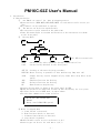
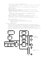
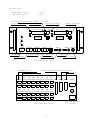
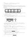
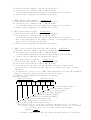
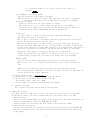
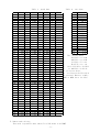
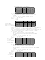
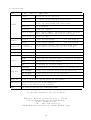
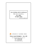
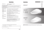
16CH STEPPING MOTOR CONTROLLER
PM16C-02Z
USER'S MANUAL
"SHEET No.2462"
APPLICATION
VER.1
OF
ELECTRONIC
DEVICES
TSUJI ELECTRONICS CO.,LTD
3739 Kandatsu-machi Tsuchiura-city
Ibaraki-pref., 300-0013 Japan
Telephone +81-29-832-3031
Fax
+81-29-832-2662
e-mail [email protected]
url http://www.tsujicon.jp
PM16C−02Z Command List(for RS232C,GP−IB)
mode
R/L
R/L
R
R/L
R
R
operation
remote/local select
channel read
A channel select.
B channel select.
A service request
B service request
A,B service request
SRQ cancellation
SRQ flag read out
A pos.data read
A pos.status read
B pos.data read
B pos.status read
A pos.2 byte command
command
S1□
S10
S11□
S12□
S1301
S1302
S1303
S1380
S14
S20
S21
S22
S23
S30□□
B pos.2 byte command
S31□□
Speed set command
A pos.8 byte command
R/L
Data read command
S3□
S32XXX
XXX□□
or
S32XXX
XXX□□B
S33XXX
XXX□□
or
S33XXX
XXX□□B
S4XY
R
Data write command
S5XY□□
R/L
Status & LS read
S6
b-lash correct set
〃
read out
BX±DDDD
BX?
B pos.8 byte command
remarks
S1R:remote change S1L:local change
receive form R□□
□:0∼F
□:0∼F
SRQ for A channel stop
SRQ for B channel stop
SRQ for A,B channel
or GP-IB command:"IFC"
receive form R□□
(HEX)
receive form R□□□□□□ (HEX)
receive form R□□
(HEX)
receive form R□□□□□□ (HEX)
receive form R□□
A position 2 byte command
08:+jog,
09:-jog
0C:+CSPD scan
0D:-CSPD scan
0E:+scan
0F:-scan
16:pause on
17:pause off
18:hold off
19:hold on
1E:+scan&HP stop 1F:-scan & HP stop
40:slow stop
80:EM.stop
B position 2 byte command
08:+jog,
09:-jog
0C:+CSPD scan
0D:-CSPD scan
0E:+scan
0F:-scan
16:pause on
17:pause off
18:hold off
19:hold on
1E:+scan & HP STP 1F:-scan & HP stop
40:slow stop
80:EM.stop
S34:L speed S35:M speed S36:H speed
A position 8 byte command
XXXXXX:HEX position data
10:CSPD REL.IDX 11:CSPD ABS.IDX
12:REL.IDX
13:ABS.IDX
character B for "back-lash correct"
B position 8 byte command
XXXXXX:HEX position data
10:CSPD REL.IDX 11:CSPD ABS.IDX
12:REL.IDX
13:ABS.IDX
character B for "back-lash correct"
data read command
X:channel No. Y:data No.
receive form R□□□□□□ (HEX)
3byte from read data address
data write command
X:channel No. Y:data No.
□□:data (HEX)
status & LS read
receive form R□□
data set 0∼±9999(Decimal)
receive form ±DDDD(DEC)
Contents
1.Introduction
page
1) Characteristics ・・・・・・・・・・・・・・・・・・・・・・・・・・ 1
2) Concept of PM16C control
2.Panel layout
1)Front panel layout Rear Panel Layout・・・・・・・・・・・・・・・・ 3
2)Function SW (in detail)・・・・・・・・・・・・・・・・・・・・・・・ 4
3.Setting the motor characteristics
1) Power on ・・・・・・・・・・・・・・・・・・・・・・・・・・・・・ 5
2) Prepare the data setting・・・・・・・・・・・・・・・・・・・・・・ 5
3) Procedure of data setting ・・・・・・・・・・・・・・・・・・・・・ 5
4) Finish to set data・・・・・・・・・・・・・・・・・・・・・・・・・ 7
4.Local mode driving
1) Speed selection ・・・・・・・・・・・・・・・・・・・・・・・・・・ 7
2) Changing the driving mode ・・・・・・・・・・・・・・・・・・・・・ 7
3) Channel selection ・・・・・・・・・・・・・・・・・・・・・・・・・ 8
4) Jog driving ・・・・・・・・・・・・・・・・・・・・・・・・・・・・ 8
5) Position data preset・・・・・・・・・・・・・・・・・・・・・・・・ 8
6) Synchronous driving ・・・・・・・・・・・・・・・・・・・・・・・・ 8
7) Auto hold-off ・・・・・・・・・・・・・・・・・・・・・・・・・・ 8
8) Inhibiting Jog・・・・・・・・・・・・・・・・・・・・・・・・・・・ 8
9) Hand box operation ・・ ・・・・・・・・・・・・・・・・・・・・・・ 8
5.Remote mode driving
1) Parallel I/O data communication(omitted)
2) RS232C,GP-IB data communication
・・・・・・・・・・・・・・10
a)Introduction b)Baud rate /address set SW・・・・・・・・・・・・11
c)Character structure・・・・・・・・・・・・・・・・・・・・・・・・11
d)Soft ware Hand Shake ・・・・・・・・・・・・・・・・・・・・・・・11
e)Connection between PM16C and other instruments・・・・・・・・・・11
2-1)Command in detail(for both RS232C and GP-IB)・・・・・・・・・・11
a) Channel select,channel read and remote/local change ・・・・・・・11
b) Data & status read・・・・・・・・・・・・・・・・・・・・・・・・12
c) Motor control command ・・・・・・・・・・・・・・・・・・・・・・12
2 byte command form(S30XX,S31XX)
① +,- jog command
08H(CW),09H(CCW)・・・・・・・・13
② +,- constant speed scan
0CH(CW),0DH(CCW)・・・・・・・・13
③ +,- scan command
0EH(CW),0FH(CCW)・・・・・・・・13
④ speed select command
S34,S35,S36 ・・・・・・・・・・13
⑤ pause/restart (for synchronous started)16,17H・・・・・・・13
⑥ hold off set/reset
18,19H・・・・・・・13
⑦ scan & HP stop command
1E,1FH・・・・・・・14
⑧ slow stop command
40H ・・・・・・・・14
⑨ EM stop command
80H ・・・・・・・・14
8 byte command form(S32XXXXXXXX,S33XXXXXXXX)
⑨ constant speed relative index scan
10H ・・・・・・・・14
⑩ constant speed absolute index command 11H ・・・・・・・・15
⑪ incremental index command
12H ・・・・・・・・15
⑫ absolute index command
13H ・・・・・・・・15
d) Data read out command ・・・・・・・・・・・・・・・・・・・・・・16
e) Data write on command ・・・・・・・・・・・・・・・・・・・・・・17
f) Limit SW & remote/local mode read ・・・・・・・・・・・・・・・・17
2-2) Procedure of data communication by GP-IB/RS232C・・・・・・・・・17
2-3) Sample Program of data communication ・・・・・・・・・・・・・・17
6.Additional Functions1 "Auto Backlash elimination"・・・・・・・・・・・・18
7.Additional Functions2 "Pulse output style change " ・・・・・・・・・・・19
8.connection with outer equipment・・・・・・・・・・・・・・・・・・・・・・20
9. Specifications ・・・・・・・・・・・・・・・・・・・・・・・・・・・・・・21
PM16C-02Z User's Manual
1.Introduction
1) Characteristics
①
One PM16C can control les than 16 stepping motors.
*Characteristics(HSPD,MSPD,LSPD,RATE,LMSW)of each motors can be set as you
like.
*Any channel can be inhibited to operate.
② Two motors can be driven synchronously.
*The two motors can be started at the same time.
*Limit SW status,Pulse out status and Position of the two motors are shown
on the front panel.
③ Driving Mode
REMT
LOCL
SET UP
HP
REMT
LOCL
ABS
DRIVING
REL
SCAN
(all LED are turned off)
:Controlled by other equipment through communication line
:Controlled by Switches on the front panel
SET UP :Setting of the motor driving procedure
DRIVING :Motor driving is possible in this mode(set up lump turn off)
SCAN
ABS
REL
HP
:Simple driving(can be stopped only by Limit SW or Stop SW on front
panel)
:Absolute Position Set Driving
:Relative Position Set Driving
:Home Position Stop Driving
*Present driving mode is shown on the front panel by LED
*Modes,and position are memorized as back up data by battery for five years.
*The data can be set in REMT mode, as above shown.
*Use the data communication forms as below.
1 GP-IB(EX. NEC PC9801-29N)
2 RS232C
3 Handy console(PM16-HD1:option)
④ Motor is stopped,when
a. Limit Switch is detected.
b. Home Position Switch is detected.
c. Software Limit Switch is detected.
d. stop switch is pushed.
*Enable/disable can be set for each motor.(a,b,c)
*Contact type can be set for each motor.(a,b,c)
- 1 -
*(d) function is enable in both remote/local.
*(c) is a function in which the motor is stopped at the point set by front panel
or by remote operation.
*In the case of a∼d, the motor is stopped through slow stopping process to
prevent detuning.
⑤ Hand box operation
*Only 2 channel can be operated, which are displayed on the front panel.
*CW/CCW jog operation is possible.
*By use of the Hand box, you can operate PM16C, while you watch the machine
moving.
If you need more multi-function, handy console :PM16-HD1 is useful.
Please contact us, and order please.
⑥ Hold off :When motor is stopped, power is automatically turned off.
*Each channel can be set to take the hold-off function,or not.
*The hold-off can be set externally by command through communication line.
⑦Jog switch is used for:
a. Any numbers of steps(1∼9999) driving.
b. Inching driving; Only when you keep to push the jog SW,
Jogging continues.
2) Concept of PM16C control
Pulse motor controller ;PM16C-02Z has ①a CPU which controls the hole of the
system, ② two CPU which control the stepping motors. The connections between the
two CPU and 16 of stepping motors are changed properly. Present positions, present
velocities, differential velocities in starting and stopping phase, etc. are
stored in the memories as battery back up, which are read out and renewed any time
you need.
Push-Button SW
LED,Lump
in, out port
display
CPU
for A ch
control
total
control
CPU
display
C
H
A
N
G
E
R
communication port
PIO
GP-IB
RS232C
memory
pulse out
connectors
for 16 of PM
・
・
CPU
for B ch
control
C
H
A
N
G
E
R
- 2 -
・
・
input connectors
for LS
2.Panel layout
1)Front panel layout
Rear panel layout
Fig.1
Fig.2
Driving direction (status of pulse out) lamp
LS status lamp
Position Display
selected CH display
channel select SW
PM16C-02Z
A position
CH
B position
CH
TALK
SET DATA
SET DATA
LSTN
SRQ
POWER
Power SW&LAMP
Function SW&LAMP
FUNCTION
CHANNEL
CONTROL
JOG
channel select SW
control SW
Step mode SW&LAMP
MODE
SPEED
HAND BOX
speed select
Hand box connector
Fig.1 Front panel layout
CH 0 pulse out
CH 0 LS in
Parallel I/O connector GP-IB connector
RS232C connector
CH0
CH1
CH2 CH3
CH4
CH5 CH6 CH7
PULSE PULSE PULSE PULSE PULSE PULSE PULSE PULSE
PIO GP-IB RS232C DIPSW
LS IN LS IN LS IN LS IN LS IN LS IN LS IN LS IN
F3A
CH8
CH9
CHA CHB
CHC
CHD CHE CHF
PULSE PULSE PULSE PULSE PULSE PULSE PULSE PULSE
AC100V
LS IN LS IN LS IN LS IN LS IN LS IN LS IN LS IN
Fig.2 Rear panel layout
- 3 -
AC85-264V 47-440Hz
are available
2)Function SW (in detail)
REMT
LOCL
MODE
MODE
SET UP
MODE
A
REMT
LOCL
; External control mode
; Manual driving mode. PM16C is operated by Panel SW.
If you keep the SW to be pushed,and turn the power on,
then Motor Speed is set to be default data.
Default:HSPD=3700PPS,MSPD=650PPS,LSPD=10PPS,
RATE=300mS/1000PPS,hold off mode,LS/N.O
jog pulse counts=1,CWLS=+1000000,CCWLS=-1000000
*Each pushing changes the remote/local alternately.
It can be also operated externally.
SET UP ; If you push this SW when motor remains stationary in LOCL,
then the mode is changed into set up mode.
Please set the data for motor driving in this mode.
AB
B
By these SWs, you can select which motor is driven.
If you select SW AB,two motors are driven at the same
time.
PRESET ; a. In DRIVING mode:data of digital SWs are set as present data.
By A/AB/A SW, you can select the CH to which data are preset.
PRESET
b. In set up mode:The values of data are increased.
(The value of Soft ware LS is set by digital SW.)
INC
START ; a. In DRIVING mode:Function is changed in accordance with
mode display lamp
START
Data
STOP
mode lmp mode movement when ST sw is on
all off scan prepare scan. waiting to set direction
ABS on
ABS scan start to ABS. pos. set by digital SW.
REL on
REL scan start to REL counts set by digit. SW.
HP on
HP
prepare scan till HP LS stopping
*In scan and HP, scanning is prepared by pushing this SW.
However, the scanning can not start without setting CW/CCW
decision by jog SW.
b. In set up mode:Showing data are changed by this SW.
Right after entering into set up mode, CW LS data is shown.
And,CCW LS,HSPD,MSPD,RATE,LS status are shown next to next.
STOP ; a. In DRIVING mode:Motor is stopped in both REMT and LOCL modes.
b. In set up mode:The value of the data are decreased.
(Software LS value is set by digital SW. )
DEC
- 4 -
caution
* mode change SW : ABS→REL→HP→scan are circular changed.
* speed change SW :L→M→H are circular changed.
3.Setting the motor characteristics
In PM16C-02Z, each data of 16 stepping motors can be set and stored, which is kept as
battery back up. The data are kept to be memorized until reset. Then, accurate control
is realized for any system. In setting mode, pulse out is stopped. data can not be set
during JOGGING.
1) Power on
When Power SW is turned on, status become to be default mode within 1s.
default
operation
mode
driving
mode
driving
position
LOCL
REL
A
speed
setting
MID
Other data are set as the value which are the one last time turned off the power,
because the all of these data are kept by battery back up.
2) Prepare the data setting
In LOCL mode, set up mode is selected by set up SW.
Then, A position display shows the data.
Caution)The display shows the number as HEX(0∼F), then 6and b might be complex.
Please take care this point.
Display
in detail
9 0
set No.
CH
0 0 0
F F
5
0000
set. data
set ch
The channel you want to set data is shown in A position display. The channel
can be changed by INC/DEC SW under the display. You can not set the channel shown in
B position display.
Then, you should change the channel of B position.
3) Procedure of data setting
A. Digital CW LS
setting No. 7 *Right after entering the set up mode
a) Push the data SW ( AB SW ), and select the setting No.7.(7 is not shown, but it is
after E.)
b) Set the data by INC SW (A SW) and DEC SW (B SW).
The data's mean the absolute position where you want to stop the motor during CW
driving.
c) Channel can be changed by the SW under the display.
B. digital CCW LS setting
setting No.8
a) Push the data SW ( AB SW ), and select the setting No.8.
b) Set the data by use of INC SW (A SW) or DEC SW (B SW).
The data mean the absolute position where you want to stop the motor during CCW
driving.
c) Channel can be changed by the SW under the display.
C. HSPD (Highest Speed)setting
Setting No.9
- 5 -
a) Push the data SW ( AB SW ), and select setting No.9.
b) Set data by use of INC SW (A SW) or DEC SW (B SW).
A relationship between data and speed can be known by use of table 1.
c) Channel can be changed by the SW under the display.
D. MSPD (Middle Speed)setting
Setting No.A
a) Push the data SW ( AB SW ), and select setting No.9.
b) Set data by use of INC SW (A SW) or DEC SW (B SW).
A relationship between data and speed can be known by use of table 1.
c) Channel can be changed by the SW under the display.
E. LSPD (Lowest Speed)setting
Setting No.B
a) Push the data SW ( AB SW ), and select setting No.B.
b) Set data by use of INC SW (A SW) or DEC SW (B SW).
A relationship between data and speed can be known by use of table 1.
This is the speed which is the primary value in accelerational driving, or the
final value of decelerational driving
c) Channel can be changed by the SW under the display.
F. RATE (accelerational/decelerational rate)setting
setting No.C
a) Push the data SW ( AB SW ), and select setting No.C.
b) Set data by use of INC SW (A SW) or DEC SW (B SW).
A relationship between data and speed can be known by use of table 2.
c) Channel can be changed by the SW under the display.
G. LMSW (Limit SW etc.)setting
setting No.D
a) Push the data SW ( AB SW ), and select setting No.D.
b) Set data by use of INC SW (A SW) or DEC SW (B SW).
c) LS status can be set, while you see the LED to know the present status.
(turned on:LS on, turned off:LS off) (details are shown in next page "LS data
structure)
d) If highest bit is set to zero (<7FH), which means motor off, then CW and CCW LS
lamps are switched to show that the motor can not be driven.
e) Channel can be changed by the SW under the display.
*LS data structure
Higher bit of Hex
Lower bit of Hex
1/0
1/0
1/0
1/0
1/0 1/0
1/0
1/0
① CW LS contact(1:B,0:A)
② CCW LS contact(1:B,0:A)
③ ZERO LS contact(1:B,0:A)
④ CW LS (1:enable,0:disable)
⑤ CCW LS (1:enable,0:disable)
⑥ DIGITAL LS (1:enable,0:disable)
⑦ hold off(1:normal,0:hold off)
⑧ motor enable(1:motor on,0:motor off)
①,② CW/CCW LS A/B contact type setting
When these bits are 1, they are B contacts. when they are 0, A contacts.
A contacts :when LS is struck, the contact becomes electrically to be CLOSE.
It is normally open. (so it is also called as N.O contact )
Drawing:
B contacts :When LS is struck, the contact becomes electrically to be open.
- 6 -
.
It is normally CLOSE. (so it is also called as N.C contact )
Drawing:
③∼⑤ ZERO,CW and CCW LS enable
Each LS can be set to be enable or disable.
When this bit is 1, the LS is enable. When this bit is 0, the LS is disable.
Please care that motor can not stop when LS is kept to be disable.
⑥ Digital LS enable
digital LS can be also set to be disable or enable.
When this bit is 1, it is enable. When this bit is 0, it is disable.
If digital LS is enable, motor can stop at the absolute position where is
internally set by digital SW(CW/CCW) as same as hardware LS.
⑦ hold off
IF some torque is required to keep the motor remaining stationary,
power should be kept to be turned on.
But, if there is not such a requirement, some motor drivers can be hold off to
prevent the heating up and to save the power.
When you use these types of drivers, motor can be more effectively driven by
this bit operation. When this bit is 1, hold off signal is disable so that power
is kept to be turned on all time. When this bit is 0 in manual mode, the power is
turned on 0.1s before jog starting, and turned off 0.1S after jog finishing.
*The motor, whose power is required to be hold off in remote mode,
should be controlled by the sequence, in which the "hold off" is set to be
disable before jog starting, and reset to be enable after jog finishing.
⑧Motor enable
You can set some motors impossible to drive by use of this bit setting.
When this bit is 1, it is normal driving mode that motor can be driven as you
like.
When this bit is 0, motor can not be driven by any manual SW operation.
*If you set the motor impossible to drive by this way, the motor becomes that can
not be driven by any remote operation.
H. Jogging count setting
setting No. E
a) Setting No.E is selected by pushing the data SW (AB SW).
b) Set the data by INC SW (A SW) and DEC SW (B SW).
The possible dates' range is 1∼9999.
c) You can change the channel by the SW under the display.
4) Finish to set data
Turn off the set up SW, and get back to driving mode.
4.LOCAL mode driving
Only when remote/local SW is set to be local, the motor can be driven in local mode.
If this SW is remote, you need to push the SW once, and reenter into local mode.
1) Speed selection
By use of speed selecting PB, any speed can be selected from the three speed that are
preset in each channel, which are HSPD,MSPD and LSPD.
Starting speed of acceleration and final speed of deceleration is LSPD.
2) Changing the driving mode
By use of driving mode selecting PB, you can select the mode as you like:HP,REL,ABS
and scan(scan mode is the case that all LED which show driving mode are turned off.).
a. HP jogging
- 7 -
When Start PB is pushed, motor is prepared to start, and then start lamp is
turned on.
And after that, when the driving direction is given by jog SW operation , the motor
is started to search the HP in the given direction, and stop at the HP LS. You can
stop the motor at any position by use of stop SW. These preparation can be reset by
stop PB.
b. REL/ABS index jogging
In REL mode,when you push the start SW, motor is relatively driven by pulse counts
which is preset with digital SW.
IN ABS mode,when you push the start SW, motor is driven to the ABS position where
is set by digital SW.
The motor is also stopped by LS and stop SW.
c. Scan jogging
When you push the START SW, START lamp is turned on to show stand-by OK. Next, you
give the direction by jog SW, then scan is started in the direction you set.
The motor is stopped at LS, and also stopped by stop PB.
These preparation can be reset by stop PB.
3) Channel selection
While pulse is not being sent, the channel you like to control can be changed by
CH select SW in local mode. In the display, the position of the last selected motor
is shown. If the SW is operated during pulse-sending, the channel is not changed
until finishing the pulse out. Two display (A/B)can not control same channel at the
same time.The system are programmed that same CH can not be selected at the same time.
4) Jog driving
In the direction which is set by jog SW, pulses are sent and motor is driven.
If you keep the SW to be pushed more than 0.5 seconds, this scan is started.
5) Position data preset
Index data can be shown and set in the display by use of PR PB and A/AB/B
PB.
6) Synchronous driving
Both A and B can be synchronously driven. Then, two motors are started at the same
time.
Push AB PB.
7) Auto hold-off
If you set the motor hold off, the power of the motor is turned on only when
the motor is being driven.
8) Inhibiting Jog
If you set the motor off, any operations shown above can't drive motors.(refer P.6
3-3)-G.)
9) Hand box operation
By use of hand box,you can drive motors while you watch the mechanical moving.
Then, two CH displayed front panel can be operated as CW/CCW jog driving.
You can change control CH on the front panel.
- 8 -
Table 1
No.
0
1
2
3
4
5
6
7
8
9
A
B
C
D
E
F
10
11
12
13
14
15
16
17
18
19
1A
1B
1C
1D
1E
1F
20
21
22
23
24
25
26
27
28
29
2A
2B
2C
2D
2E
2F
PPS
5
10
25
50
75
100
150
200
250
300
350
400
450
500
550
600
650
700
750
800
900
1,000
1,100
1,200
1,300
1,400
1,500
1,600
1,700
1,800
1,900
2,000
2,100
2,200
2,300
2,400
2,500
2,600
2,700
2,800
2,900
3,000
3,100
3,200
3,300
3,400
3,500
3,600
No.
30
31
32
33
34
35
36
37
38
39
3A
3B
3C
3D
3E
3F
40
41
42
43
44
45
46
47
48
49
4A
4B
4C
4D
4E
4F
50
51
52
53
54
55
56
57
58
59
5A
5B
5C
5D
5E
5F
PPS
No.
3,700 60
3,800 61
3,900 62
4,000 63
4,100 64
4,200 65
4,300 66
4,400 67
4,500 68
4,600 69
4,700 6A
4,800 6B
4,900 6C
5,000 6D
5,100 6E
5,200 6F
5,300 70
5,400 71
5,500 72
5,600 73
5,700 74
5,800 75
5,900 76
6,000 77
6,100 78
6,200 79
6,300 7A
6,400 7B
6,500 7C
6,600 7D
6,700 7E
6,800 7F
6,900 80
7,000 81
7,100 82
7,200 83
7,300 84
7,400 85
7,500 86
7,600 87
7,700 88
7,800 89
7,900 8A
8,000 8B
8,200 8C
8,400 8D
8,600 8E
8,800 8F
speed data
PPS
9,000
9,200
9,400
9,600
9,800
10,000
10,200
10,400
10,600
10,800
11,010
11,210
11,410
11,600
11,800
11,990
12,200
12,400
12,600
12,790
12,990
13,200
13,400
13,620
13,810
14,000
14,200
14,400
14,620
14,830
15,010
15,200
15,390
15,580
15,770
15,970
16,180
16,400
16,610
16,830
17,060
17,240
17,420
17,600
17,800
17,990
18,180
18,380
Table 2 rate data
No.
90
91
92
93
94
95
96
97
98
99
9A
9B
9C
9D
9E
9F
A0
A1
A2
A3
A4
A5
A6
A7
A8
A9
AA
AB
AC
AD
AE
AF
B0
B1
B2
B3
B4
B5
B6
B7
B8
B9
BA
BB
PPS
18,660
18,940
19,230
19,530
19,840
20,160
20,500
20,830
21,190
21,550
21,930
22,320
22,730
23,150
23,590
24,040
24,510
25,000
25,510
26,040
26,600
27,170
27,620
28,090
28,570
29,070
29,590
30,120
30,680
31,250
31,850
32,470
33,110
33,780
34,480
35,210
35,970
36,500
37,040
37,600
38,170
38,760
39,370
40,000
No.
0
1
2
3
4
5
6
7
8
9
A
B
C
D
E
F
10
11
12
The setting Range
HSPD=0∼BB
MSPD=0∼BB
LSPD=5∼A1
RATE=0∼12
Care)HSPD<LSPD
or MSPD<LSPD
If you set as above,
no acceleration/deceleration
is operated. However, simply
HSPD or MSPD drive are done.
5.Remote mode driving
This mode is possible when remote/local SW shows to be REMT.
- 9 -
mS/1000PPS
1,000.0
800.0
600.0
500.0
400.0
300.0
200.0
150.0
125.0
100.0
75.0
50.0
30.0
20.0
15.0
10.0
7.5
5.0
3.0
If the remote/local SW shows LOCL, push the SW again or send the command
externally to change the mode to be REMT. And ,after that, continue to operate
as below.
Remote mode driving can be operated by;
1 Parallel I/O
2 GP-IB
3 RS232C
These communication mode can be selected by setting SW of rear panel.(as shown below)
The setting SW should be pushed before power turned on.
1
2 3
4 5
6 7
8
on
↑
↓
off
↑ ↑
↑ ↑
When GP-IB is selected → 24 23
↑ ↑
When RS232C is selected →(N.C)A
↑
↑
22
↑
B
↑
↑
21
↑
C
1:ON→RS232C port enable
2:ON→GP-IB port enable(*1)
3:
4:
5:
GP-IB my address or
6:
RS232C baud rate
7:
setting
8:
↑
↑
20 (my address) A:9600 baud If more than
↑
B:4800 baud two SWs are
D→→→→
C:2400 baud on, higher
D:1200 baud is selected.
*When both RS232C and GP-IB are ordered at the same time, RS232C is selected.
*1)
By use of the optional handy console (PM16-HD1) is connected to RS232C port in GP-IB mode,
less than additional 6 motors can be controlled (position monitoring, jog,scan,REL.IDX,ABS
IDX and preset) during GP-IB control.
1) Parallel I/O data communication(omitted)
2) RS232C,GP-IB data communication
a) Introduction
A PM16C-02Z has a GP-IB control IC;TMS9914A. and has a RS232C control IC;
HD64941. In this system, nonsense command or impossible command(EX. reverse drive
during normal drive)are ignored so that almost all time you can access from these
communication lines(protect from hung up).
Receive form should be S□・・・・□CR+LF*.
When CR(0DH)+LF(0AH)is detected during receiving, the command is rapidly analyzed
and done by PM16C-02Z. However, top character is not S , no operation is done.
When PM16C receives information that some data should be returned back, the data
are rapidly prepared and sent back. These operations are done for about less
than 1mS.
Drive command form is;R□・・・・□CR+LF.
Remote controls such as receiving, analyzing and doing from RS232C/GPIB line are ope
rated by interrupting in PM16C-02Z. Therefore, these operations need not have
waiting time.
Then, three types of commands are possible.
TYPE 1:rapid done・・・data reading/motor stop
TYPE 2:waiting for some status done・・・CH select
TYPE 3:some status requiring done・・・motor control
In the case of that the data are read out after sending the command of TYPE 2/3,
it is important as above shown.
*De-limitter is fixed to be CR+LF.
b)Baud rate /address set SW:as above mentioned
c)character structure
- 10 -
1.RS232C data are 1START bit +8 bit data +1stop bit no parity(fixed)
2.De-limitter is fixed to be CR+LF.
3.Send/receive command code is ASCII.
d)In RS232C communication, software hand shake (XON,XOFF)is not supported.
e)Connection between PM16C and other controller( in the case of RS232C.
GP-IB is omitted here.)
1.PANEL:DB25S
CABLE:DB25P
2.PIN ASSIGN (→shows the flow of data)
PM16C-02Z
other controller
1 SHIELD
can be omitted
1 SHIELD
2 TXD
3 RXD
3 RXD
2 TXD
5 CTS
4 RTS
7 SIG.GND
7 SIG.GND
6 DSR
8 DCD
20 DTR
RS23C2C debug tool
If RS232C line can not work well, the cause of that is hard to be found. Therefore,
we prepared the tool for helping to solve these problems. Please keep the stop PB on while
power is turned on, then received character is displayed echo back. You can refer the
character and get some information about the problem you meet. If echo back is not well
displayed, the RS232C line is possible to be badly wired. Or, if you get curious
characters, baud rate and parity should be examined.
2-1)Command in detail(for both RS232C and GP-IB)
a) Channel select,channel read and remote/local change command
If these commands are received during pulse sending,
any operations are not started before finishing the pulse out.
It is enable only in REMT mode.
CH reading out and REM/LOCL changing can be operated both in remote/local. Dates are
read out as the receive form below.
command form
S
1 □
□
channel data(0∼F)
(In Ch reading and remote/local changing, it can be ignored.)
R:Remote mode change (TYPE 3)
L:LOCL mode change (TYPE 3)
0: position channel read (TYPE 1)
1:A position channel select(TYPE 2)
2:B position channel select(TYPE 2)
3:SRQ (next 2characters are 8 bit pattern )
4:SRQ status read out (automatically cleared after
SRQ status reading out)
B7
command
EX) S1301 : A pos.stop SRQ
- 11 -
B0
B0:A pos.stop SRQ
B1:B pos.stop SRQ
B7:ignore SRQ(reset)
S1302 : B pos.stop SRQ
S1380 : SRQ reset,SRQ clear
Receive form
R
□ □
B Ch data (0∼F),SRQ status lower bites
A ch data (0∼F),SRQ status higher bites
* When ch is selected, old data are saved and new data are set. These process takes
a few times.(about 30mS) Therefore, you should send the command after
completing the ch selection . The completing can be known by Ch reading out command.
b) Data & status read command
At any time, position data and status are usually read out by this command.
This is enable in whichever modes remote/local.
command form
S
2 □
0:A
1:A
2:B
3:B
position
position
position
position
data read (TYPE
status read( 〃
data read ( 〃
status read( 〃
1)
)
)
)
Receive form
R
□ □
R
□ □
□ □
Status REG.
D7 D6 D5 D4 D3
D2
□ □
D1
position data
HEX CODE
Status data(2
HEX CODE
(2's compliment of 6 hex code)
ASCII
hex code)
ASCII
D0
*) Firmware version "V1.30"
BUSY
etc. can be read out by
DRIVE
"VER?" command.
DREND(V1.30∼)
COMERR(V1.30∼)
COMERR(∼V1.29, "0":V1.30∼)
LDEND
SSEND
ESEND
BUSY:shows Pulse controller is being operated now. During the moving, speed change
and pulse out command are ignored, though slow stop and EM stop command are
effective. BUSY status of OD17 shows CPU status which controls hole of the
system. On the other hand, the BUSY here shows two CPU's status (A/B)
which control A and B motors.
DRIVE :Pulse out is being continued.
DREND :Pulse out drive finished.
COMERR :The command is nonsense.
LDEND :Pulse out is stopped by CWLS and CCWLS.
SSEND :Pulse out is slowly stopped by slow stop command.
ESEND :Pulse out is rapidly stopped by EM stop command.
caution)COMERR,LSEND,SSEND and ESEND are enable, only if BUSY=0.
These bits are cleared by rewriting the next command.
LSEND,SSEND and ESEND bit are nonsense, when pulse are not sent out by the command.
c) Motor control command
Data and command are written for A position and B position control
- 12 -
2 bytes
command form
S 3 □ □ □
2 byte command
0:A position 2 byte command(TYPE 3)*
1:B position 2 byte command(TYPE 3)*
4:LSPD set(TYPE 3)
5:MSPD set(TYPE 3)
6:HSPD set(TYPE 3)
*slow stop and EM.stop command are TYPE 1.
①
+,- jog command
command
08 :+(CW) jog drive
09 :-(CCW) jog drive
command for jog drive
② +,- constant speed scan command
By this command, motor speed is set to be constant value which is preset (*) as you
like.
command
0C :+(CW) constant scan drive
0D :-(CCW) constant scan drive
* The speed is set at the value which is last selected by push SW (H,M and L) in LOCL mode,
or which is last selected by speed select command ⑧ in REMT mode. This procedure is same
in other controls shown below.
③
+,- scan command
Motor speed is increased from LSPD to set value as trapezoidal driving.
command
0E :+(CW) scan drive
0F :-(CCW) scan drive
④
speed selection command
By this command, the motor speed is selected from HSPD,MSPD or LSPD.
Both A POS and B POS are set as same value.
This command is effective for the channel whose motor remains stationary.
The channel of the moving motor is kept to store the old value.
command
EX) S34 : LSPD select
S35 : MSPD select
S36 : HSPD select
⑤ The command used to stop the motors which are started at the same time, and the
command used to reset the stop command
The below commands should be sent to PM16C before starting the two motors
at the same time.(*) If jog command is sent after stop command, motors can not
be driven until cancellation of the stop command.
command
16 : pause
17 : pause off
EX) S3016 : pause
S3017 : pause off
- 13 -
* The sequence of Synchronous start is that; 16H(pause) is given to the each controller,
and after that, 17H(pause off) is given to start two motors synchronously.
The third character shows channel, and then both 1 and 0 are effective for both A and B
channel.
⑥
hold off set/rest command
command
18 : hold off set
19 : hold off reset
EX) S3018 : A pos.hold off set
S3019 : A pos.hold off reset
S3118 : B pos.hold off set
*When you need to start the motor from the state of hold off, you should cancel the hold
off state enough time before sending the control pulse in accordance with motor's character.
Of course, when you set hold off again ,you should send the command enough time after
finishing to send the control pulse.
⑦
⑧
scan & HP stop
By this command,
command
1E : +scan & HP
1F : -scan & HP
EX) S301E :
command
scan and home position LS detection are done.
stop
stop
A pos. +scan & HP stop
slow stop command
Velocity is decreased by the rate whose value is preset.
command
40 : slow stop
EX) S3040 : A pos.slow stop
⑨
EM stop command
by this command, pulse out is rapidly stopped.
Care for motor speed, because motor is possible to be detuned.
command
80 : EM stop
EX) S3180 : B pos. EM stop
8 bytes command form
(TYPE 3)
S 3 □ □ □
□ □
□ □ □
□
2 byte command
2:A position 8 byte command
6 byte data(6 HEX CODE in ASCII style)
3:B position 8 byte command
⑨ constant speed relative index scan
Motor is driven at the preset constant speed.
command
□□ □□ □□ 10 : constant speed REL.IX drive
222∼216
27∼20(data3)
(data1) 215∼28
(data2)
- 14 -
Sample(Out put pulse is 2's complement)
PULSE OUT
0
(CW)
+10
(CW)+8,388,607
(CCW)
-10
(CCW)-8,388,608
data 1
00H
00H
7FH
FFH
80H
data 2
00H
00H
FFH
FFH
00H
data 3
00H
0AH
FFH
F6H
00H
⑩
constant speed absolute index command
By this command, motor is driven at preset constant speed.
command
□□ □□ □□ 11 : constant speed ABS.IX drive
222∼216
27∼20(data3)
(data1) 215∼28
(data2)
Setting sample
Objective address is
shown as 2's complement
objective address
0
+10
+8,388,607
-10
-8,388,608
data 1
00H
00H
7FH
FFH
80H
data 2
00H
00H
FFH
FFH
00H
data 3
00H
0AH
FFH
F6H
00H
*caution:When the number is not coincident in absolute command operation,
Counter is possible to be different between display and control.
Then, you should select channel again. When you use the command other than
explained in this manual, these troubles are possible to happen.
⑪ incremental index command
Relative setting index drive is done by this command.
The speed is increased and decreased between LSPD and MSPD.
command
□□ □□ □□ 12 : incremental IDX. drive
22
2 ∼216
27∼20(data3)
15
(data1) 2 ∼28(data2)
pulse counts
are shown
as 2's complement
setting sample
⑫
pulse out
0
(CW)
+10
(CW)+8,388,607
(CCW)
-10
(CCW)-8,388,608
data 1
00H
00H
7FH
FFH
80H
data 2
00H
00H
FFH
FFH
00H
data 3
00H
0AH
FFH
F6H
00H
absolute index command
Absolute setting index drive is done by this command.
The motor speed is increased and decreased between LSPD and MSPD.
command
□□ □□ □□ 13 : incremental IDX. drive
22
2 ∼216
27∼20(data3)
(data1) 215∼28(data2)
objective
is shown as
2's complement.
sample
objective address
0
+10
+8,388,607
data 1
00H
00H
7FH
- 15 -
data 2
00H
00H
FFH
data 3
00H
0AH
FFH
-10
-8,388,608
FFH
80H
FFH
00H
F6H
00H
*caution :When absolute command is done, it is doubtful that display
counter and control counter are different from each other. Then, the values
are not coincident. In such cases, please select the channel again.
That case might be happened when the nonsense command is used.
d) Data read out command
Each channel is read out by this command, which is enable both in REMT and LOCL
modes.
command form
S 4 □ □
(TYPE 1)
read data address(0-F)
read channel address(0-F)
receive form
R □ □
□ □
□ □
data (HEX CODE ASCII)
3 bytes are returned from read data address.
data address
contents
0
position data(165,164)
1
〃
(163,162)
2
〃
(161,160)
3
digital CWLS (165,164)
4
〃
(163,162)
5
〃
(161,160)
6
digital CCWLS(165,164)
7
〃
(163,162)
8
〃
(161,160)
9
HSPD
$A
MSPD
$B
LSPD
$C
RATE
$D
LMSW etc.
$E jog pulse counts
$F
b0:CW LS A/B
b1:CCWLS A/B
b2:Z LS A/B
b3:CW LS enable
b4:CCWLS enable
b5:digital LS enable
b6:hold (1:ON 0:OFF)
b7:motor off
jog pulse counts
MDA+$E
〃
MDA+$F
- 16 -
- 17 -
e) Data write on command
By this command, basic data stored in each ch can be rewritten. This is enable in
REMT mode. However,speed data cannot be rewritten while motor is driving, and the
data are rewritten automatically after stopping the motor.
command form
S 5 □
□ □
□
(TYPE 1)
write data(2 HEX CODE in ASCII style)
write data address(0-F)
write channel address(0-F)
f) Limit SW & remote/local mode read
By this command,LS status and remote/local mode status are read out in any time.
However, it is required for approximately 30ms that the ch is changed by the
command. In LS status read,more 10mS is required.
command form
S 6
(TYPE 1)
receive form
R □ □
data (HEX CODE in ASCII style)
B7:
B6:B POS Z. LS on → 0
B5:B POS CCW LS on → 0
B4:B POS CW LS on → 0
B3:REM/LOC status(1:REM)
B2:A POS Z. LS on → 0
B1:A POS CCW LS on → 0
B0:A POS CW LS on → 0
upper HEX CODE
lower HEX CODE
2-2) Procedure of data communication by GP-IB/RS232C
Ⅰ)External controller gives the command to GP-IB/RS232C lines.
Ⅱ)When all command is received by PM16C02Z, analyzed and driven rapidly.
Time for doing the command is vary for status of system, for command types, etc.
Ⅲ)In command with receiving operation, data prepared by the command is returned
back to the external controller when PM16C02Z is set as a talker.
Ⅳ)All command can be sent as the form which is divided by comma(","). In receiving
data, comma is recognized as the pause between two commands. Then, each
command is rapidly recognized and done. If there are non-sense commands,
they are ignored.(EX. speed change during jogGING) There are some commands which
requires some time for operating.
EX.)When you want to set 3ch to A position, and A ch to B position:
S113,S12A RETURN+LF
2-3) Sample Program of data communication(address of PM16C02Z:7,delimiter:CR+LF)
a)select A position as 8 CH
PRINT@ 7;"S118"
b)select B position as C CH
PRINT@ 7;"S12C"
c)+scan is operated in A position
PRINT@ 7;"S300E"
d)write 80H to 5 ch address 9 data(HSPD)
PRINT@ 7;"S55980"
- 18 -
e)read out the present A position pulse count
PRINT@ 7;"S20"
:data read out command
INPUT@ 7,1;A$
:data input
PRINT A$
:data print
6.Additional Functions1('96.10.01∼) "Auto Backlash elimination"
It can be operated only by GP−IB or RS232C communication lines.
What is the Auto Backlash Elimination?
By this function, you can preset the value of elimination step, then motor is driven
to position where you want to stop the motor after the elimination step driving.
For example; If you set -5000 as the elimination step, at first the motor is driven
to the position where the count is X-5000. And after that, the motor is driven back
to the position for +5000 steps, then driving is finished to reach the position of X.
If the elimination step is +, the motor approaches to the final point from + site.
(if the elimination step is -,the motor approaches to the final point from - site.)
By this function, backlash of the mechanics is eliminated.
◎ Command Reference
elimination step count set(kept by battery back up)
set command
BX±DDDD
B:elimination step count
X:channel(0∼F)
±:+or−(direction from which motor is driven to approach the final position )
DDDD:decimal counts(0000∼9999)
example
B0+5000,BF−3000
read out the elimination step counts(it's read out any time you can.)
read out command
BX?
receive form
±DDDD
±:+ or −(approach direction) DDDD:decimal counts(0000∼9999)
example
+5000,−3000
◎ auto backlash eliminative driving
move command
Auto backlash eliminative driving can be operated by adding "B" to A/B position 8 byte
command.
例)S32XXXXXX□□B
S32 :A position 8byte command XXXXXX:driving data(HEX)
□□
:command(relative driving、absolute driving)
B:auto backlash elimination is operated.
S33XXXXXX□□B
S33 :A position 8byte command XXXXXX:driving data(HEX)
□□
:command(relative driving、absolute driving)
B:auto backlash elimination is operated.
◎ When you use backlash elimination;
1.If the stop command is sent to PM16C externally, or front panel stop SW,the motor is
slowly stopped at the point.
After that,the backlash elimination sequence is normally cancelled.
2.If you have set the stopping SRQ, the SRQ is expressed after motor stopping.
3.During the sequence of backlash elimination, if LS in driving direction is struck,
- 19 -
the motor is slowly stopped and after that the sequences cancelled.
4.By addition of this function, the direction of motor driving become to be more complex,
therefore limit SW setting should be required to be care.
7.Additional Functions 2 "Pulse output style change "
PM16C-02Z has two pulse output styles for the Driver's requirement.
One is CW pulse + CCW pulse style (P-P style) and the other is pulse + direction
(P-D style).
PM16C-02Z is set P-P style as a default setting when shipping.
This function can change the pulse output style if necessary.
The pulse output style is set to A position and B position control IC in the PM16C-02Z
individually.
So you can set P-P style to A position and P-D style to B position, for example.
The motor control using one control window (ex. A position) is the same style pulse outp
ut instead of selected channels.
A position control and B position control can also be set to P-D style.
Setting check and change
1. Press SETUP button in local mode and go into setup mode.
2. When pressing the REM/LOC button, A, B control button lamp indicate the pulse
output style. If the lamp off, the button indicate P-P style and if the lamp on,
the button indicate P-D style. (Confirmation pulse output style)
3. While pressing the REM/LOC button, pressing A button or B button cause the change
of lamp on/off status alternately. (Change of pulse output style)
4. If the setting is changed, new setting will be valid after next power on.
The pulse output style will be memorized by the backup battery.
- 20 -
8.connection with outer equipment
1) connection with drivers
connector PIN assign
DE9S(TO DRIVER)
+5V
CWP
1 ○
(PULSE)
2 ○
CCWP
3 ○
(DIRECTION)
4 ○
5 ○
H.OFF
6 ○
7 ○
+12V→
8 ○
0V→
9 ○
Driver
300Ω
signal which informs to the
driver that PM16C power on.
1KΩ
CW LS
DE9P(TO LS)
1
2
3
4
5
6
7
8
9
CCWLS
ZERO
LS
proximity SW connection
LS type:both N.O and N.C ok
○
○
○
○
○
○
○
○
○
CW LS
1P
2P
CCWLS
12V
Max.0.8A
ZERO(HP)
LS
12V
SIG
0V
3P
4P
12V
SIG
0V
6P
7P
12V
SIG
0V
FG
PM16C
caution)Connector shell size of DE9P and 9S is varied from each maker's.
Outward form <35W can be used for PM16C.
DE-C1-J6(JAE), XM2S-0911(OMRON) and HDE-CTF(HIROSE) are possible to be used.
- 21 -
9. Specifications.
Power
AC 85V ∼ 264V 47 - 440Hz
control
capability
IN/OUT
display
digital sw
50VA
16 motors can be controlled.
2 motors can be controlled synchronously.
out put
CW, CCW, HOLD OFF(5V 8mA:plus common)for each 16 motor
driver. can choose PULSE, DIR output signal.
pulse rate
1∼40KPPS
pulse con.
D sub 9S(female)
limit sw input
CW-LS, CCW-LS, HOME-LS 12V 5mA(minus common) and power
supply +12V for sensor (total 1A) for each motor
limit sw con.
D sub 9P(male)
position
7 digit position display
For each 2ch(A,B)
channel
1 digit channel display
For each 2ch(A,B)
±7 digit
digital sw
counter preset, relative data for REL and ABS index
moving digital limit data set, For each 2ch(A,B)
ch.sel.sw
call channel to the two control windows(A,B)
ctl.sel.sw
decide control enable/disable for A,B control
control
step mode
PRESET
preset digital sw data to the selected display
START
moving start for selected channel according to the mode
STOP
stop moving for selected channel
JOG
jog stepping for selected channel
SCAN MODE
continuous scan for selected channel. directed by JOG sw
ABS IDX MODE
moving to the indicated position by the digital sw
REL IDX MODE
moving indicated value by the digital sw
HP STOP MODE
stop by Home Position Limit Sw
speed sel.
select L, M, H speed. can set freely for each channel
rem.control
remote control over PIO, GP-IB, RS232C port
(Ethernet for -02Z-NT instead of RS232C)
cace
EIA 3 UNIT rack mount type (132H×482W×420D)
For the other information, feel free to ask us.
Tsuji Electronics Co., Ltd.
Tel:+81-(0)29-832-3031 Fax:+81-(0)29-832-2662
E-mail: [email protected]
URL : http://www.tsujicon.jp
3739 Kandatsu-machi Tsuchiura-city, Ibaraki 300-0013, Japan
- 22 -