1
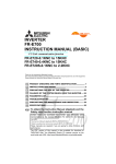
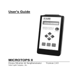
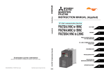
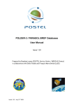
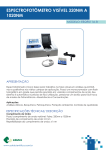
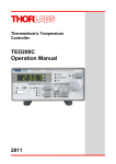
Series 700 Laser Diode Mounts
User’s Manual
Warranty
Newport Corporation warrants this product to be free from defects in material
and workmanship for a period of 1 year from the date of shipment. If found to
be defective during the warranty period, the product will either be repaired or
replaced at Newport’s option.
To exercise this warranty, write or call your local Newport representative, or
contact Newport headquarters in Irvine, California. You will be given prompt
assistance and return instructions. Send the instrument, transportation prepaid, to
the indicated service facility. Repairs will be made and the instrument returned,
transportation prepaid. Repaired products are warranted for the balance of the
original warranty period, or at least 90 days.
Limitation of Warranty
This warranty does not apply to defects resulting form modification or misuse of
any product or part. This warranty also does not apply to fuses.
This warranty is in lieu of all other warranties, expressed or implied, including
any implied warranty of merchantability or fitness for a particular use. Newport
Corporation shall not be liable for any indirect, special, or consequential
damages.
Newport Corporation, Irvine,
California, has been certified
compliant with ISO 9002 by
the British Standards
Institution.
Corporate Headquarters
Newport Corporation
1791 Deere Avenue
Irvine, CA 92714
Telephone: 949-863-3144
Facsimile: 949-253-1800
Belgium
Telephone: 016-402927
Facsimile: 016-402227
Canada
Telephone: 905-567-0390
Facsimile: 905-567-0392
France
Telephone: 1-60 91 68 68
Facsimile: 1-60 91 68 69
Germany
Telephone: 06151-36 21-0
Facsimile: 06151-36 21-52
Italy
Telephone: 02-924-5518
Facsimile: 02-923-2448
Japan
Telephone: 03-5379-0261
Facsimile: 03-5379-0155
Netherlands
Telephone: 030-6592111
Facsimile: 030-6570242
Switzerland
Telephone: 01-740-2283
Facsimile: 01-740-2503
Taiwan R.O.C.
Telephone: 2-2769-9796
Facsimile: 2-2769-9638
United Kingdom
Telephone: 01635-521757
Facsimile: 01635-521348
Safety Precautions
Caution
Never look directly into the output aperture of a laser diode package or mount at
any time. Laser diodes emit invisible radiation that can cause damage to the
eyes.
Observe electro-static discharge avoidance procedures when handling laser
diodes. Check that all equipment is disconnected from the mount before
connecting a laser diode.
Model 700 Series Mounts
The Model 700 Series Temperature Controlled Mount is a research quality mount that provides precise temperature control of laser diodes.
Thermoelectric modules and an efficient thermal design permit cooling
or heating. A dry nitrogen purge nipple allows the laser diode to be surrounded in a nitrogen environment preventing condensation at below
ambient temperatures.
Connectors on each side of the Model 700 Series mount provides a convenient manner to connect a Model 300 Series Temperature Controller
and a Model 500 Series Laser Diode Driver. The mount comes assembled
with a 1.5” riser and slotted baseplate that allows for adjustment on one
by one inch grid as well as on metric tables.
Temperature Control
The Model 700 Series Temperature Controlled Mount has been designed
to handle high power laser diodes such as Spectra Diode Labs model
SDL-2460 series and Sony’s model SLD304. Two 12.5 watt thermo-electric modules actively cool and heat the laser diode. These modules are
series connected and handle a maximum of 6.0 Amps at 7.5 volts.
Laser Diode Mounting
Two laser diode mounting plates are available for use with the Model
700 Series Temperature Controlled Mount. All mounting plates may be
rotated 90ϒ so that the polarization plane may be changed.
A combination 9mm/5.6mm mounting plate handles packages such as
Sharp’s C&D types, Spectra Diode Labs’ G1 & V1, and NEC & Toshiba’s
visible laser diodes. The second mounting plate is for TO-3 laser diode
packages.
A blank mounting plate having a predrilled pilot hole is also offered and
can be custom milled by the customer to accept open air or non-standard
laser diode packages.
Collimating Lens Housing (Model 700C)
The housing provides a versatile assembly for collimating the output of a
laser diode. Recessed, precision screws provide an adjustment of the op-
tics in the X and Y directions while a especially designed lens cartridge
focuses the lens. The range of adjustment is 4mm in the X and Y directions and 10mm along the focal axis.
All screws have 80 threads per inch and use non-outgassing grease for
smooth and accurate adjustments. Safety covers on all adjustment screws
prevent inadvertent misalignment of the optics.
The lens cartridge can be easily removed permitting different sets of optics to be inserted without disassembling the collimating lens housing.
Laser Diode Collimation
Precision collimating optics having a 5mm clear aperture and optimized
for wavelengths between 600nm to 1020nm is available (part# 700-42).
Specifications
Temperature Controlled Mount
Size
a) without Collimating Lens Housing
b) with Collimating Lens Housing
Optical Height:
a) with riser
b) without riser
c) without riser and baseplate
4” x 4” x 1.6”
4” x 4” x 2.9”
4”
2.5”
2.0”
The Temperature Controlled Mount can be mounted without the
baseplate or riser using standard opto-mechanical hardware.
TE Modules
Two 12.5W, 20mm x 20mm
maximum 6.0 Amps and 7.5 volts.
Laser Diode Mounting Plates
a) 9mm/5.6mm packages (base diameter)
b) TO-3 packages
c) Blank plate with predrilled pilot hole
Temperature Sensors
a) 10 kΩ thermistor
b) AD592CN sensor
Connectors
a) D-sub 15-pin male, Temperature Controller connection
b) D-sub 9-pin male, Laser Diode Driver connection
c) Isolated BNC, for modulation input
d) Purge Nipple, for dry nitrogen
Collimating Lens Housing
Lens Adjustment
a) X and Y directions
b) focal axis
4mm, 80 threads per inch
10mm, 80 threads per inch
Lens Cartridge
9mm inside diameter
Collimating Optics
A standard lens assembly is
available to use with the Collimating Lens Housing
Part No.
Focal
Length
Numerical
Aperture
Working
Distance
Optical
Correction
Window Window
Quality Thickness
700-42
5.0 mm
0.50
2.67 mm
600-1020 nm λ/20
0.30 mm
Field-Of-View Clear
Diameter
Aperture
0.014 mm
5.0 mm
Specifications are subject to change without notice.
Using the Temperature Controlled Mount
The Model 700 Series Temperature Controlled Mount is versatile for
controlling the temperature of laser diodes having many different types
of packages. This mount can also be used to cool IR detectors for noise
reduction in low level signal detection. Dry nitrogen may be used to purge
the inside water vapor to prevent condensation when operated at below
ambient temperatures. Mounting a device is a simple procedure but care
must be taken not to damage the TE modules and to ensure that the connections to the laser diode and photodiode are correct.
Mount Assembly
Access to the laser diode mounting plate is from the front, while access to
the electrical connections is from the rear of the mount. The unit comes
completely assembled as an aid in showing how each component fit together. The front cover is held on with four bottom head screws. Removing them exposes the laser diode mounting plate, attached thermistor and
AD592 sensor, and the TE modules held in place with heat transfer grease.
Removal of the rear cover should be done with the front cover or collimating lens housing secured to the main housing to avoid stressing thermistor and TE module wires. Carefully lay the mount down on its front
cover and remove the four screws. This exposes the rear of the main
housing where the electrical connections are made to the two D-sub connectors, and an isolated BNC connector.
Laser Diode Handling Precautions
NOTE
Laser diodes are extremely sensitive to static discharge. The
manufacturer’s guidelines should be followed at all times when
handling laser diodes.
a.
b.
c.
All operators must be properly grounded before handling any laser
diode.
All soldering irons must be properly grounded.
All related test and assembly equipment must be properly
grounded.
Laser Diodes can only withstand a maximum reverse voltage of 2 to 3
volts across their leads and no more than their maximum rated current in
the forward direction. Always follow the manufacturer’s instructions for
removing and handling laser diodes.
Additional precaution must be taken when soldering to the leads of a
laser diode. Excess heat from soldering damages the laser facet. Care
must be taken to provide a heat sink between the laser diode and the leads
during soldering. Also, always follow the laser diode manufacturer’s specifications for maximum temperature and soldering times.
It is recommended that the connection to the laser diode remain floating
relative to Chassis Ground (earth ground). This prevents AC transients or
other voltage potentials arising from multiple earth ground loops front
damaging the laser diode. Extreme care must be taken to ensure that all
devices including the Model 500 Series and any devices connected to the
laser diode, such as an external modulations source, are all grounded to
the same earth ground point. It is strongly recommended that this common earth ground be the chassis ground (pin 3, brown wire) on the sub-D
9-Pin connector. If you have any questions on earth grounding a laser
diode contact a Newport applications engineer.
Mounting a Laser Diode
The Model 700 Series Temperature Controlled Mount has three mounting plates available. These mounting plates include; a) a 9mm/5.6 mm
mounting plate for laser diodes having a base diameter of 9mm and 5.6mm,
b) an optional TO-3 mounting plate for higher power laser diodes, and c)
an optional blank mounting plate having a predrilled pilot hole that can
be milled for custom and non-standard laser diode packages. Each mounting plate has a hole milled from the bottom side that comes within .040”
of the top surface of the mounting plate. This hole has a precision 10 kΩ
thermistor and AD592CN sensor epoxied inside.
9mm/5.6mm Combo Mounting Plate
Many laser diodes come in a package that has a base diameter of 9mm.
A list of some manufacturer laser diodes having these package types
includes the following:
Manufacturer
Hitachi
Mitsubishi
Sharp
Sony
NEC
Toshiba
Spectra Diode Labs
Package type
All 9mm cans
All 9mm cans
C and D type
V labeled models
NDL 3200, VDL
TOLD 9200, VLD
G1 and V1
The figure below shows the 9mm mounting plate with its retaining plate.
The retaining plate is attached to the 9mm mounting plate by two screws.
To mount a laser diode, remove the screws for the retaining plate and
carefully center the laser diode over the center hole. The retaining plate
will center the laser diode when it is secured by the two screws.
To orient the laser diode for vertical or horizontal polarization, loosen
the two retaining screws and rotate the laser diode can to the correct position.
To remove the mounting plate from the main housing the wires from the
thermistor or the AD592 sensor must be unsoldered from the D-sub 15pin connector, so they may be pulled through the hole on the bottom of
the main housing. Before soldering the sensor to the D-sub connector
consult the Temperature Controller Connection section for the correct
sensor polarity.
TO-3 Mounting Plate
The TO-3 mounting plate, shown in the figure below, provides a convenient method for mounting laser diode packages in TO-3 cans. With the
front cover removed, align the TO-3 package’s holes with the holes on
the mounting plate and secure the laser diode with the 6-32 screws.
The mounting plate is factory aligned so that the theta parallel polarization plane is horizontal. To rotate the diode or vertical polarization, remove the four nylon screws holding the baseplate. Reposition the TE
modules to prevent them from interfering with the temperature sensor
wires then rotate the baseplate 90ϒ. Make sure that the wires are not pinched
between the TE modules and the mounting plate. Finger tighten the screws
in diagonal pairs to avoid uneven pressure that might deform or crack the
TE modules underneath.
To remove the mounting plate from the main housing the wires from the
thermistor must be unsoldered from the D-sub 15-pin connector, then
they may be pulled trough the hole at the bottom of the main housing.
See the Temperature Controller Connection section for the Correct polarity before reconnecting the temperature sensor.
Blank Mounting Plate
Open air and non-standard laser diode packages may be mounted on a
blank mounting plate. It has a pre-drilled pilot hole in the center of the
mount and may be milled by the customer to accept many different laser
diode types.
Thermoelectric (TE) Modules
The Model 700 Series Temperature Controlled Mount uses two 12.5 watt
thermoelectric modules or active heating and cooling. A series connection is used to maximize their efficiency when used with a Model 300
Temperature Controller insuring that the current flow to the TE modules
does not exceed their maximum current rating. In series, these TE modules can handle a maximum of 6.0 Amps and will drop a maximum of 7.5
volts. Care must be taken not to exceed the TE modules’ maximum temperature rating of +80ϒC. If your application requires operating at a higher
temperature, contact Newport Corporation.
Even though the TE modules can dissipate up to 25 watts, at high levels
convection cooling may not be sufficient to stabilize heat dissipation,
limiting the mount’s ability to maintain laser temperatures below ambient. Fan cooling increases mount dissipation efficiency and will allow
operation at low desired temperatures, preventing thermal saturation or
runaway conditions. Consult Newport if you have requirements to lower
the temperature of a laser diode below 10ϒC.
Electrical Connections
Electrical Connections are made to the laser diode, TE modules, and temperature sensors from the rear of the mount. Connections to a Temperature Controller are made via a DB-15 and to a Laser Diode Driver via a
DB-9 connector. A BNC connector is available to input a modulation
signal either to a PC board of you own design or to a bias tee that can be
mounted inside rear compartment of the main housing.
Temperature Controller Connection
A D-sub 15-pin connector has been provided to connect the TE modules
and thermistor to a temperature controller. The Model 300 Series Temperature Controller can be connected directly to the connector using the
Newport’s cable part number 300-04. Looking from the outside of the
mount, pin numbers can be seen on the connector’s insulation found
around the pins.
Pin
1&2
3&4
7
8
Connection
TE+
TESensor+
Sensor-
Wire Color
Red
Black
White(thermistor), Red (AD592)
White(thermistor), Blue(AD592)
Pins 1 & 2 and 3 & 4 are soldered together inside the main housing. If the
maximum capabilities of the TE modules are to be used, paralleling wires
in cabling to the mount is permissible to handle 6 Amps. The pins of the
D-sub connector are each rated for 5 Amps. The Model 700 Series Temperature Controlled Mount comes with a precision 10 kohm thermistor
and a AD592 sensor. The mount comes with the thermistor connected to
the 15-pin connector. When connecting the AD592 sensor, assure that
the polarization is correct.
Laser Diode Driver Connection
A D-sub 9-pin male connector has been provided with wire pigtails to
connect to a laser diode socket. A Model 500 Series Laser Diode Driver
can be connected directly to the mount using Newport’s cable part number 500-04. Looking from the outside of the mount, the pin numbers can
be seen on the connector’s insulation found around the pins.
Pin
3
4,5
6
7
8,9
Connection
Chassis Ground
Laser Cathode
Photodiode Cathode
Photodiode Anode
Laser Anode Red
Wire Color
None
Black
White
Green
The figure below shows the three possible connections of a laser diode
and photodiode. Standard sockets may be used to connect the device.
The chassis ground connection, earth ground, can be used if there is a
danger of electrostatic discharge (ESD) to the laser diode when the collimating lens housing is not used. This connection provides a path to earth
ground for energy arising from ESD at the laser diode case. The ground
connection must be made at the laser diode and only one ground path
must be made. The mount and any equipment connected to the mount
must have only one ground path and that must be through the chassis
ground pin (pin 3) on the laser diode connector. If possible, the laser
diode should be left floating (with no connection to earth ground) to improve transient protection and to prevent ground loop potentials created
from improper earth grounding, which could damage the laser diode.
Modulation Input Connection
Above the laser diode driver connector is a BNC that can be used to input
a modulation signal. A customer designed PC board can be mounted in
the rear chamber using four pre-tapped holes. Also, a bias tee can be used
to modulate the laser diode and can be mounted in the rear chamber.
Contact Newport for additional information on using a bias tee.
Purge Nipple
To prevent condensation from occurring on the laser diode when operating below ambient temperature, a dry nitrogen purge nipple is supplied
with all mounts. The purge nipple is located on the same side as the temperature controller connector towards the front of the main housing. Flexible tubing, with an inside diameter of one sixteenth (1/16”) inch, is used
to connect the mount to a dry nitrogen source. When the collimating lens
housing is not used the flow of nitrogen must be great enough to fill the
front portion of the mount and flow out of the front cover around the
laser diode package.
General Operating Procedures
1.
2.
3.
4.
5.
Securely mount the Model 700 Series Temperature Controlled
Mount on an optical table by the baseplate supplied with the
mount.
After securing the mount, connect the cables of the temperature controller and the laser diode driver to the mount.
Set the maximum TE module current on the temperature
controller.
Set the current limit level on the laser diode driver and the
desired drive current. Turn the output of the laser diode driver
on.
Allow the mount to stabilize its temperature which may take
up to one half an hour.
WARNING
Never look directly into the output aperture of the mount at any time.
Laser Diodes emit invisible radiation that can cause damage to the
eyes. Also, take precautions to prevent specular reflections from the
laser diode’s output beam. Avoid exposure at all times to laser
emissions or collateral radiation in excess of the applicable emission
limits given in “Performance Standards for Laser Products” United
States Code of Federal Regulation, 21 CFR 1040.10(D)
Collimating Lens Housing
The Model 700C Series Temperature Controller Mount includes a complete collimating lens housing. Each collimating lens housing comes fully
assembled with the lens cartridge and protective covers in place, as shown
in the figure below. Newport offers a precision, three element, collimating lens for laser diodes.
Lens Cartridge
Each collimating lens housing has one lens cartridge supplied with it.
Remove the protective cover, then unscrew the knurled lens cartridge
from the collimating assembly. The collimating optics slide into the end
of the lens cartridge opposite the knurled end. A #2-56 set screw is used
to secure the collimating optics inside the lend cartridge. Reinstall the
lens cartridge, careful not to strip the threads (80 threads per inch with
non-outgassing grease) to a depth of 5/16” (8mm) with respect to the
surface of the housing. This insures that the lens will not touch the laser
diode package. The laser diode output beam may now be collimated by
screwing the lens cartridge into the collimating lens housing and adjusting the X-Y centering setscrews.
Collimating Optics
Collimating optics may be purchased from Newport or provided independently by the customer. Newport’s 5mm collimating lens (part #70042) is optimized for operation in the 600-1020nm wavelength range. The
lens cartridge has a 9mm inside diameter for the collimating optics assembly. The orientation of the lens with respect to the laser diode window is shown in the figure below. The lens slides into the Lens Cartridge
opposite the knurled end.
Collimating a Laser Diode
There are several methods used to collimate a laser diode. The most accurate and time consuming method uses an interferometer to look at the
interference pattern while adjusting the collimating optics until the fringe
pattern disappears.
A second method uses a beam profiler and a single lens having a long
focal length. The lens is located exactly one focal length from the measurement plane of the beam profiler. The output beam of the laser diode
is collimated when the minimum spot size is measured. The optical basis
for this method of collimation is shown in the figure below.
Focusing is accomplished by screwing the lens in and out until the output
beam of the laser diode is focused. To align the laser diode emitting aperture with the center of the lens the X and Y adjustment screws must be
used. The screws are accessed by removing the two protective caps.
Q = Df (mm) / f (mm)
where:
1) Q = full angle divergence from the collimator
2) Df = spot width at one focal length from the lens (1/e2)
3) f = focal length of lens, and is true for any laser mode or mixture of
modes.
NOTE
Disconnect laser diode from laser diode driver instrument before
starting the alignment procedure. Never look into the output aperture
of a laser diode when it is operating.
P/N 24726-01
IN-11971