1
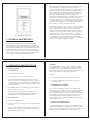
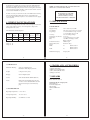
TABLE OF CONTENTS
1. SAFETY RULES
2-3
2. GENERAL DESCRIPTION
4-5
3. OPERATING INSTRUCTIONS
LP2000
DIGITAL LOOP
AND Ipsc TESTER
INSTRUCTION MANUAL
3.1 SOCKET OUTLET
6-7
3.2 THREE PHASE AND OTHER
UNTERMINATED SUPPLIES
7
3.3 CIRCUITS INCORPORATING RESIDUAL
CURRENT DEVICES
7-8
4. WIRING FAULT DIAGNOSIS
8
5. SPECIFICATIONS
9
5.1 ELECTRICAL
9
5.2 MECHANICAL
10
5.3 ENVIRONMENTAL
10
6. SPARES AND ACCESSORIES
11
7. REPAIRS
11
8. LIMITED WARRANTY
12
Martindale Electric Company LTD
1. SAFETY RULES
SAFETY CHECK
Double check the lead connections before making a test.
WARNING
Are you following all the instructions?
DISCONNECT FROM SUPPLY BEFORE OPENING
TESTER
Use only the specified type of fuse and insert it correctly.
Do not use leads that are damaged and in need of repair.
Do not use in wet conditions.
THIS INSTRUMENT SHOULD ONLY BE USED BY A
COMPETENT, SUITABLY TRAINED PERSON.
This tester has been designed with your safety in mind. However, no
design can completely protect against incorrect use. Electrical
circuits can be dangerous if lack of caution and/or poor safety
practices are used.
REMEMBER
SAFETY IS NO ACCIDENT
READ THE MANUAL
Read this Instruction Manual carefully and completely. Voltages and
currents within the capability of this instrument can be hazardous.
Follow the instructions in this manual for every test. Read and
understand the general instructions before attempting to use this
tester. Do not exceed the limits of this tester.
-2-
-3-
Three measurement modes, selected by the function switch, enable
loop measurements to be made between the phase and earth
conductor in the mains lead and prospective short circuit current
measurements between the phase and neutral conductors in the mains
lead. A reading is initiated and displayed when the test button is
depressed. The lamps indicate the status of the phase neutral and
phase earth conductors and the status of those lamps can be
interpreted to determine the absence of a conductor or the reversal of
two conductors (See Wiring Fault Diagnosis Table Page 8). Fuse
protection is provided by a 5A, anti-surge fuse fitted on the printed
circuit board and a 13A fuse in the plug. Thermal overload protection
is provided by inhibiting tests for a ten second period after any test,
thus preventing over heating of the internal circuitry.
Fig. 1 Digital Loop and Ipsc Tester
2. GENERAL DESCRIPTION
The principal of operation of the tester is that a voltage proportional
to the incoming supply on no load is compared to that same voltage
when a 10Ω load is connected for two half cycles of the mains
supply. These signals are combined and fed to a digital volt meter
LSI device whose output provides a reading of the loop resistance or
Ipsc. This device has a hold facility so that after 1 second, the
reading is retained for as long as the test button is depressed. If there
is a perturbation on the incoming supply during the measurement
cycle, the reading could be inaccurate. It is, therefore, recommended
that at least two repeatable readings are obtained.
The model LP2000 Digital Loop Tester is a hand-held, mains
powered instrument designed to measure the loop and prospective
short circuit current (Ipsc) of electrical circuits in accordance with
the 16th Edition of the IEE wiring regulations (BS EN 7671). It has a
3½ digit liquid crystal display and is available in various versions.
The loop is measured over two ranges to 199.9Ω with auto range at
15Ω and with resolutions of 0.01 and 0.1Ω. The Ipsc is measured
over one range of 19.99 kA with a resolution of 0.01kA.
-4-
3. OPERATING INSTRUCTIONS
3.1 SOCKET OUTLET
A. Phase Earth Loop
1) Set the function switch to P/E.
2) Connect the tester to the socket with its mains lead.
3) Check that the PE and PN lamps light. If either fails to light
then do not operate the tester, switch off the socket as there may
be a wiring fault. Correct the fault before proceeding further and
check the instrument. The Wiring Fault Diagnosis Table on page
8 may be of assistance.
4) If the READY symbol on the LCD shows, press and hold the test
button to obtain a loop reading.
5) The reading obtained in 4 should now be compared to the
appropriate table in the IEE Wiring Regulations (BS7671) to
verify the protection device against disconnection time.
B. Bonded Metalwork
1) Set the function switch to P/E2.
2) Connect the tester to a socket adjacent to the metal work with its
mains lead.
3) Plug the wander earth lead into the 4mm socket beside the mains
inlet on the tester and press the probe firmly onto the bonded
metal work. Proceed as in A, 3-5.
-6-
-5-
WARNING:
The Wiring Regulations require protective conductors (including
Bonded Metalwork) to be checked with a continuity tester before
performing a loop test. Care should be taken since when a test is
performed on a system with a poor earth, the tip of the wander earth
lead if connected will be energised for two half cycles.
C. Ipsc
1) Set the function switch to Ipsc and proceed as in A, 2-4.
2) The reading obtained will be the prospective short circuit
current (Ipsc) in kA.
3.2 THREE PHASE AND OTHER
UNTERMINATED SUPPLIES
As an accessory a multi-purpose mains lead is available which
facilitates the testing of supplies that have no socket outlet. This lead
has a moulded Euro free socket at one end and double insulated
phase, neutral and earth tails at the other. The earth tail is terminated
with a shrouded crocodile clip and the phase and neutral tails have
interchangeable fused probes and crocodile clips. If there is no
neutral available on a three phase system then the neutral probe/clip
should be taken to earth.
3.3 CIRCUITS IN CORPORATING
RESIDUAL CURRENT DEVICES
If a residual current device is incorporated in the installation, it may
be found that the RCD will trip during a phase earth loop test.This is
likely to occur where the tripping time is 20ms or less since the tester
passes up to 24A to earth during a test for up to 2 half cycles.
-7-
It will therefore probably be necessary to bypass the RCD with links
during the test, making sure that the links are removed after the test.
With the RCD bridged, the protection of the circuit against earth faults
is removed and precautions should be taken to ensure that the circuit is
not used when the RCD is in operative.
NOTE: AN INDICATION ON THE P/E LAMP DOES NOT
INDICATE A SATISFACTORY EARTH
WE RECOMMEND THAT, IF THIS
INSTRUMENT IS USED FOR
VERIFYING ELECTRICAL
INSTALLATIONS, IT IS RECALIBRATED EVERY 12 MONTHS
It will be necessary to isolate the live side of the RCD before inserting
and removing links. Depending upon the type of installation, the
electricity supply authority may have to be consulted before the supply
can be isolated.
4. WIRING FAULT DIAGNOSIS
5. SPECIFICATION
The two neon lamps indicate the status of the socket phase-neutral and
phase-earth conductors and so can be interpreted to diagnose the
wiring fault in the socket.
5.1 ELECTRICAL
The table below aids this diagnosis.
Supply Voltage:
Test Current:
Loop Range:
Lamp
Neutral
Disonn.
Phase
Disconn.
Phase &
Neutral
Reversed
Earth
Disconn.
Phase &
Earth
Reversed
P/N
O
O
X
X
O
P/E
X
O
O
O
X
Accuracy:
Temperature Coefficient:
Ipsc Range:
Fuse:
Transient Protection:
Thermal Protection:
Safety:
EMC:
Lamp on: X
Lamp off: O
200 to 260V rms, 50/60Hz
24A, rms, for two half cycles at 240V
0 to 15Ω nominal in steps of 0.01Ω
15 to 199.9Ω in steps of 0.1Ω
±2% of reading, ±2 digit
±0.1%/°C
0 to 19.99kA in steps of 0.01kA
5A, HBC, Anti-Surge ceramic,
DIN 5 X 20mm
VDR at input
Electronic delay
To
LVD:
To
Installation Category:
Category III
-8-
5.2 MECHANICAL
BS EN 50081-1
BS EN 50082-1
BS EN 61010-1
-9-
6. SPARES AND ACCESSORIES
Instrument Housing:
54 X 190 X 90mm approx.
Moulded in ABS and polycarbonate
Weight:
0.4kg (Less Carry Case)
Display:
Custom Liquid Crystal
Socket:
4mm Shrouded Mains CEE22 (IEC320)
Leads:
Mains lead with moulded plug(13A fuse)
on 240V versions Wander Earth Lead with
fused retractable probe and 4mm safety
plug.
5.3 ENVIRONMENTAL
(1)Wander Earth Probe
(2)Mains Lead standard TL205
(3)Fuse (Internal)FUSE 5A250
(4)Flying Lead TL85.
7. REPAIRS
Please return the tester to:
Martindale Electric Company Ltd
Metrohm House
Penfold Trading Estate
Imperial Way
Watford WD24 4YY
UK
Operating Temperature: 0°C to +40°C
Storage Temperature:
-20°C to +70°C
Operating Humidity:
90% RH max at +40°C
-10-
-11-
8. LIMITED WARRANTY
Martindale Electric Co Ltd warrant instruments and test equipment
manufactured by them to be free from defective material or factory
workmanship and agree to repair or replace such products which, under
normal use and service, disclose the defect to be the fault of our
manufacturing, with no charge for parts and service. If we are unable to
repair or replace the product, we will make a refund of the purchase price.
Consult the Instruction Manual for instructions regarding the proper use
and servicing of instruments and test equipment. Our obligation under this
warranty is limited to repairing, replacing or making refund of any
instrument or test equipment which proves to be defective within 24
months from the date of original purchase.
This warranty does not apply to any of our products which have been
repaired or altered by unauthorised persons in anyway so as, in our sole
judgement, to injure their stability or reliability, or which have been
subject to misuse, abuse,misapplication, negligence or accident or which
have had the serial numbers altered, defaced or removed. Accessories, not
of our manufacture used with this product, are not covered by this
warranty.
To register a claim under the provisions of this warranty, return the
instrument or test equipment to Martindale Electric Co Ltd, Metrohm
House, Penfold Trading Estate, Imperial Way, Watford, WD24 4YY.
Upon our receipt and inspection of the product we will advise you as to
the disposition of your claim.
-12-
Martindale Electric Company LTD
Metrohm House
Penfold Trading Estate
Imperial Way
Watford
Herts WD24 4YY
T: 01923 441717
F: 01923 446900
Email: [email protected]
web: www.martindale-electric.co.uk
LITLP2000
ISSUE 3 08/2004
ALL WARRANTIES IMPLIED BY LAW ARE HEREBY LIMITED
TO A PERIOD OF 24 MONTHS, AND THE PROVISIONS OF
THE WARRANTY ARE EXPRESSLY IN LIEU OF ANY OTHER
WARRANTIES EXPRESSED OR IMPLIED.
The purchaser agrees to assume all liability for any damages and
bodily injury which may result from the use or misuse of the product
by the purchaser, his employees, or others, and the remedies provided
for in this warranty are expressly in lieu of any other liability
Martindale Electric Co Ltd may have including incidental or
consequential damages.
Martindale Electric Co Ltd reserve the right to discontinue models at
any time, or change specification, price or design, without notice and
without incurring any obligation.