1
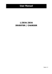
Flame detector ( UV/IR Type )
RFD-2000X User’s Manual
Rezontech Co., Ltd
Co.,Ltd.
UV/IR Type Flame Detector
RFD-2000X
TABLE OF CONTENTS
1 Product Overview
1.1 Product Introduction
1.2 Contents of User Manual
1.3 Revision of User Manual
1.4 Warranty
2 Technical Specifications
2.1 Electrical Specifications
2.2 Mechanical Specifications
2.3 Environmental Specifications
3 Installation
3.1 Unpacking & Checking
3.1.1 Product Compositions
3.1.2 Components
3.1.3 Necessary tools
3.2 Selection of Installation Location
3.2.1 Cone of Vision
3.2.2 Range of Detection
3.2.3 Environment points to be considered when use
3.3 Installation and Electrical Wiring
3.3.1 Wiring Detector
3.3.1.1 Conduit Installation
3.3.1.2 Cable Selection for Electrical Wiring
3.3.1.3 Conduit or Gland Standard (Connector)
3.3.2 Using of bracket during installation
3.3.2.1 Bracket Specification
3.3.2.2 Installation of detector with bracket to the wall or the ceiling
3.3.3 Terminal Wiring
3.3.3.1 Relay Signal
3.3.3.2 4-20mA (Current Source Wiring Contact)
3.3.3.3 RS485
3.3.3.4 External Recovery Signal Electrical Wiring
3.3.3.5 Signal of Electrical wiring for
3.3.4.
external remote self-test
Installation/Setting
3.3.4.1 Sensitivity setting
3.3.4.2 Setting of delay time
3.3.4.3 Setting of others function
3.3.5.
Ground connection
3.3.5.1 Internal Ground connection method
3.3.5.2 External Ground connection method
Document No. Manual-2000X Rev.2
March 2012
- 1 -
Co.,Ltd.
UV/IR Type Flame Detector
RFD-2000X
4 Operation
4.1 Product checklist
4.2 Initial Operation of Product
4.3 Safety Handling
4.4 Product Testing
5 Maintenance & Troubleshooting Instructions
5.1 Tools of Maintenance and Products Training
5.2 Maintenance Procedures
5.3 Troubleshooting
5.3.1 No LED responds after the power connection.
5.3.2 Yellow LED blinking (2Hz)
5.3.3 When receiver unable to detect various signal
6 Customer Support
6.1 Contacts Information
7 Appendix
7.1 Abbreviation
7.2 Choosing of Wiring
7.2.1 Reference: Standard Chart for Power Supply Electrical Wiring during
setting (AWG Standard)
7.2.2 Things to be consider when choosing electrical wiring for power supply
7.3 Certification & Approvals
Document No. Manual-2000X Rev.2
March 2012
- 2 -
Co.,Ltd.
UV/IR Type Flame Detector
RFD-2000X
1. Product Overview
1.1
Product Introduction
Model RFD-2000X from Rezontech Co., Ltd. is UV/IR type flame detector. It activates
alarm signal or fire extinguishing system via fire or flame detection. This function can be
used directly with output terminal and through connected control circuits are also available.
Various output methods are available for choice:
ㆍ Dry contact Relays (Fire, Fault, Warning)
ㆍ 4~20mA Current Output
ㆍ RS-485 Communication
RFD-2000X is a product with additional Internal/External recovery feature which enables to
be widely used in difference applications.
1.2
Contents of User Manual
All the information about detectors and its features are described on this handling manual.
its contents consist of 7 different sections as per stated on [Table 1] below .
Title
1. Product Introduction
Content
General introduction, products overview, brief
introduction on each part
2. Technical Specification
Electrical, mechanical and environmental specifications
3. Installation
Wiring, mode select, proper installation
4. Operation
Operation mode and user interface display
5. Maintenance &
Troubleshooting
6. Customer Support
7. Appendix
Maintenance and technical support procedure
About This product will be customer service will
describe the information
Abbreviations, authentication, and parts will be describe
information about products
[Table 1] Contents of User Manual
Document No. Manual-2000X Rev.2
March 2012
- 3 -
Co.,Ltd.
1.3
UV/IR Type Flame Detector
RFD-2000X
Revision of User Manual
Version
Date of Revision
1.0
March, 2010
2.0
March, 2012
Content
Registration of document
para# 2.2.2 3.2.2, 3.3.2,
3.3.4
Remarks
amendment
[Table 2] Revision of User Manual
1.4
Warranty
Rezontech warrants the Models RFD-2000X to be free from defects in workmanship or
material under normal use and service within two years from the date of shipment.
Rezontech will repair or replace without charge any such equipment found to be defective
during the warranty period. Full determination of the nature of, and responsibility for,
defective or damaged equipment will be made by Rezontech’ personnel.
Defective or damaged equipment must be shipped to Rezontech’ plant or representative
from which the original shipment was made. In all cases this warranty is limited to the
cost of the equipment supplied by Rezontech. The customer will assume all liability for
the misuse of this equipment by its employees or other personnel.
All warranties are contingent upon proper use in the application for which the product was
intended and does not cover products which have been modified or repaired without
Rezontech’ approval, or which have been subjected to neglect, accident, improper
installation or application, or on which the original identification marks have been removed
or altered.
Except for the express warranty stated above, Rezontech disclaims all warranties with
regard to the products sold, including all implied warranties of merchantability and fitness
and the express warranties stated herein are in lieu of all obligations or liabilities on the
part of Rezontech for damages including, but not limited to, consequential damages
arising out of, or in connection with, the performance of the product.
Document No. Manual-2000X Rev.2
March 2012
- 4 -
Co.,Ltd.
UV/IR Type Flame Detector
RFD-2000X
2. Technical Specifications
2.1
Electrical Specifications
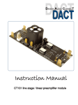
[Figure 1] TB1 Terminal address at product cover
2.1.1
Electrical
ㆍ Recommended Operating Voltage : 24VDC
ㆍ Rating Voltage : 17VDC ~ 32VDC
ㆍ Max Input Voltage : 36VDC
ㆍ Max Consumption Power : 1.8W (at 17VDC )
ㆍ Normal Average Current : approximate 35mA (at 24VDC)
ㆍ Max Operating Current : approximate 70mA
(at 17VDC, during detection of fire or self-diagnosis test)
2.1.2
Relay Output
ㆍ 2A 28VDC, 4A 125VAC, 2A 250VAC
ㆍ Dry Contact
ㆍ A(Normally Open) or B(Normally closed)
2.1.3
4~20mA Current Output
ㆍ Non-isolation output, Common 24V-_IN(-Power)
ㆍ Max. Terminating Resistance : 500Ω
ㆍ 0mA (+0.5mA) : Connection Fault
ㆍ 2mA (±0.5mA) : Self-diagnosis test Fault
ㆍ 4mA (±0.5mA) : Normal
ㆍ 8mA (±0.5mA) : IR Detection
ㆍ 12mA (±0.5mA) : UV Detection
ㆍ 16mA (±0.5mA) : Warning (UV and IR Detection, fire occurs during delay time)
ㆍ 20mA (±0.5mA) : Fire Detection
Document No. Manual-2000X Rev.2
March 2012
- 5 -
Co.,Ltd.
2.1.4
UV/IR Type Flame Detector
RFD-2000X
RS485 Communication
ㆍ Non-isolation output (2 wiring)
ㆍ Communication Speed : 9600bps
2.1.5
LED Indicator
ㆍ Two LED's(Yellow, Red) indicator
- Yellow LED : Provides indication of Normal or Fault state
- Red LED : Provides indication of Warning or Alarm state
ㆍ Product reset process : Yellow & Red LED intersection blinking repeatedly (3 sec)
ㆍ Normal : Yellow LED blinking (0.5Hz)
ㆍ Power supply or Self-diagnosis test fault : Yellow LED blinking (2Hz)
ㆍ Warning : Yellow LED blinking (0.5Hz) and Red LED blinking (2Hz)
ㆍ Alarm : Yellow LED blinking (0.5Hz) and Red LED lighting
ㆍ Warning at BIT Fault : Yellow LED blinking (2Hz) and Red LED blinking (2Hz)
ㆍ Alarm at BIT Fault : Yellow LED blinking (2Hz) and Red LED lighting
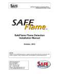
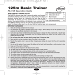
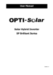
Grounding
Yellow LED
Green LED
[Figure 2] Product Image LED position indicator
Document No. Manual-2000X Rev.2
March 2012
- 6 -
Co.,Ltd.
2.2
UV/IR Type Flame Detector
RFD-2000X
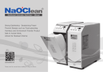
Mechanical Specifications
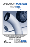
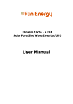
[Figure 3] Front, inch[mm]
[Figure 4] Side, inch[mm]
[Figure 5] Combination of Detector and Bracket, inch[mm]
ㆍ Enclosure (Material) : 316 Stainless Steel
ㆍ Weight : Body - approximate 2.4㎏, Overall - approximate 3.4㎏
ㆍ Dimension(Body) : W5.3[134.00] × H4.6[117.00] × D4.7[120.00] (inch[mm])
ㆍ Dimension(Overall) : W5.3[134.00] × H6.41[163.00] × D14.39[365.68] (inch[mm])
ㆍ Color : Metal
ㆍ Electrical connection (External) : 1/2 inch NPT-14, M20 X 1.5
ㆍ Wire gauge (Power supply & Signal) : AWG #12 (3.31㎟) ~ #24 (0.205㎟)
ㆍ Hazardous Area Approvals : Class I Div.1 Groups B,C and D
Class II Div.1 Groups E,F and G
Class III
Document No. Manual-2000X Rev.2
March 2012
- 7 -
Co.,Ltd.
UV/IR Type Flame Detector
RFD-2000X
ㆍ Explosion proof : ATEX Ex d IIB+H2 T6 (75℃)
ㆍ Water and Dust Tight : IP67, NEMA Type 4X
2.3
Environmental Specifications
ㆍ Operating Temperature : -40℃ ~ +75℃
ㆍ Storage Temperature : -50℃ ~ +80℃
ㆍ Humidity : Relative humidity 95%
Document No. Manual-2000X Rev.2
March 2012
- 8 -
Co.,Ltd.
UV/IR Type Flame Detector
RFD-2000X
3. Installation
3.1
Unpacking & Checking
Please check the external condition of detector when unpacking the product carefully. If
there is any damage on the products, please contact the local distributor immediately or
any trouble in used products, please send it to A/S center with fee applied.
3.1.1
Product Compositions
ㆍ RFD-2000X 1EA
ㆍ BK-2(Bracket) 1EA
ㆍ Spare Bolt 1set
ㆍ Tools
3.1.2
Components
3.1.2.1 Fundamental components
Component
standard
Q'ty (pcs)
Description
Hexagon wrench Bolt
M6×10
2
Join the Detector and Bracket
4
Join the Detector
4
Install the Bracket
M6×35
Hexagon wrench Bolt
(OEM)
Metric button screw (+)
M5×30
[Table 3] Fundamental components
3.1.2.2 Spare components
Component
Standard
Q'ty (pcs)
Description
Hexagon wrench Bolt
M6×10
2
Join the Detector and Bracket
4
Join the Detector
4
Install the Bracket
Hexagon wrench Bolt
Metric button screw (+)
M6×35
(OEM)
M5×30
[Table 4] Space Components
3.1.3 Necessary tools
Tool name
Standard
Q'ty (pcs)
Description
Hexagon wrench driver
Metric,5M
1
Join the detector, bracket
Screw driver
+
1
Install the Bracket
[Table 5] Necessary tools
Document No. Manual-2000X Rev.2
March 2012
- 9 -
Co.,Ltd.
3.2
UV/IR Type Flame Detector
RFD-2000X
Selection of Installation Location
Minimum information will be provided below for the location selection of installation.
Please refer the information according to the purpose of your use.
3.2.1
Cone of Vision
3.2.1.1 Fuel
ㆍ N-Heptane
3.2.1.2 Cone of Vision
ㆍ Horizontal / Vertical : 90° ( 45° up, down, left, right at 50% of detection range )
[Figure 6] Cone of Vision
3.2.2
Range of Detection
The detection distance for the alarm level is 50ft(18m) from the standard fire.
The detector has two response levels.
ㆍWarning
ㆍAlarm
3.2.2.1 Detection Range of Fuels
Type Of Fuel
Maximum Distance (ft / m)
N-Heptane
98.5 / 30
[Table 6] Range of Fuels Detection
Document No. Manual-2000X Rev.2
March 2012
- 10 -
Co.,Ltd.
UV/IR Type Flame Detector
RFD-2000X
3.2.2.2 Detection Range of False Alarm
The detector is immune to a variety of false alarm sources. Representative samples of
detector's response from false alarm sources are listed below.
Radiation Source
Immunity Distance ft(m)
Indirect or reflected sunlight
No fire alarm
Incandescent lamp 100W
No fire alarm
Fluorescent light 40W
No fire alarm
Resistive electric heater 1500W
No fire alarm
Blue, Green dome light XXXW
No fire alarm
Hot plate (200℃)
No fire alarm
Halogen lamp 500W (Glass)
No fire alarm
Halogen lamp 1000W (Quartz lamp)
12 (4)
Grinding metal
3.3 (1)
Arc welding (5mm, 200A)
15 (4.6)
[Table 7] Types of False Alarm source and Its Relationship between Flame Detection
3.2.3
Environment points to be considered when use
ㆍ Installation places and availability of fuels (Family of Hydrocarbon and related
flame detection)
ㆍ install product according to its Installation space and it areas of dangerous
(internal/external etc)
ㆍ Select place of installation according to detection range and field of view
ㆍ Temperature range [Min/Max] of operation/installation
ㆍ Select the place to avoid the area with obstructed object for the appropriate installation
ㆍ Select the place to avoid the area with false alarm statuses affect to the fire detection
※ The above points of considerations are based on the basic environmental standard and
they are vary different between countries in terms of environment, usage, users etc.
Document No. Manual-2000X Rev.2
March 2012
- 11 -
Co.,Ltd.
3.3
3.3.1
UV/IR Type Flame Detector
RFD-2000X
Installation and Electrical Wiring
Wiring the Detector
3.3.1.1 Conduit installation
ㆍ Use 1/2 inch NPT-14 or M20X1.5 conduit connection or suitable explosion-proof gland
to assemble the cable and conduit to the detector.
ㆍ When using conduit connection for Division installation, conduit seals must be installed
within 18 inches (450mm) from the enclosure.
ㆍ When using conduit connection for ATEX installation, conduit seals must be placed at
enclosure.
ㆍ Install the conduit including drain holes place downward to avoid water condensation in
the detector.
3.3.1.2 Cable Selection for Electrical Wiring
ㆍ All cables to the detector should be well shielded for EMC.
ㆍ Wire gauge for detectors power supply wires.
AWG No.
Diameter(㎜)
Cross section(㎟)
24
0.511
0.205
23
0.573
0.258
22
0.644
0.326
21
0.723
0.410
20
0.812
0.653
19
0.912
0.653
18
1.02
0.823
17
1.15
1.04
16
1.29
1.31
15
1.45
1.65
14
1.63
2.08
13
1.83
2.63
12
2.05
3.31
[Table 8] American Wire Gauge Standard
3.3.1.3 Conduit or Gland Standard (Connector)
ㆍ Cable Conduit Standard : 1/2 inch NPT-14, M20 X 1.5
ㆍ Water and Dust : IP67, NEMA Type 4X
Document No. Manual-2000X Rev.2
March 2012
- 12 -
Co.,Ltd.
3.3.2
UV/IR Type Flame Detector
RFD-2000X
Using of bracket during installation
3.3.2.1 Bracket Specification
ㆍ Angle adjustment : Horizontal 180° , Vertical 180°, scale indications 15° each
When you arrange the angle, M4 Set Screw and M10-25 Hexagon Wrench Bolt
has to be released first and tighten again with 24 (N・m) Torgue for Hexagon
Wrench Bolt and 1.5 (N・m) Ttorgue for Set Screw.
ㆍ Enclosure Material : 316 Stainless Steel
ㆍ Weight : Body - approximate 2.4㎏, Overall - approximate 3.4㎏
ㆍ Dimension(Body) : W5.3[134.00] × H4.6[117.00] × D4.7[120.00] (inch[mm])
ㆍ Dimension(Overall) : W5.3[134.00] × H6.41[163.00] × D14.39[365.68] (inch[mm])
ㆍ Color : Metal
ㆍ Wall mounted size : 6Φ × 4 (5mm bolt)
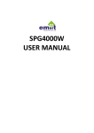
[Figure 7] Bracket BK-02
3.3.2.2 Installation of detector with bracket to the wall or the ceiling
ㆍ Necessary tool : Hexagon Wrench Driver, Screw Driver
ㆍ component : Metric M6-10 × 2 pcs, Metric M5-30 × 4pcs
ㆍ Flame detector's body and cover has to be combined with M6-35 Hexagon Wrench
Driver at 5(N・m) Torque.
ㆍ Flame detector and bracket is connected with Hexagon Wrench Bolt at 5(N・m) Torque.
Document No. Manual-2000X Rev.2
March 2012
- 13 -
Co.,Ltd.
UV/IR Type Flame Detector
RFD-2000X
ㆍ Mount the bracket with M5-30 × 4pcs bolts. Refer to Figure 17
ㆍ Detector can be installed on the wall or the ceiling with bracket. Refer to Figure 18, 19
[Figure 8] 4 Holes on bracket
for mounting detector
[Figure 10]
Ceiling mount
[Figure 9] Wall mount
Document No. Manual-2000X Rev.2
March 2012
- 14 -
Co.,Ltd.
3.3.3
UV/IR Type Flame Detector
RFD-2000X
Terminal Wiring
This is the reference for the user on how all the connection of the electrical wiring are
connected to each system or product as per stated below.
3.3.3.1 Relay Signal
- Fire Relay
The following signal occurs when fire is detected
ㆍ The operational status of fire relay according to detector's condition.
Relay status
TB1
Fire Relay
Normal
(De-Energized)
Fire
(Energized)
5,20
ALM_N.C
Closed
Open
6,19
ALM_N.O
Open
Closed
7,18
ALM_COM
Common
Common
- 2A@28VDC, 4A@125VAC, 2A@250VAC
[Table 9] Fire Relay operated
ㆍ Interlink wiring of Power Supply, Fire Relay, Fault Relay
[Figure 11] Terminal wiring diagram schematic at fire alarm relay
Document No. Manual-2000X Rev.2
March 2012
- 15 -
Co.,Ltd.
UV/IR Type Flame Detector
RFD-2000X
- Fault Relay
This signal shows up when product is not working properly or the fire signal is not
functional.
※ Before power supply is on, FLT_N.O is connected because Fault Relay is not in error
status.
ㆍ Fault Relay Operated
Type of Fault
Descriptions
Power Supply
The error status of external and internal power supply
Self Testing
The error status of basic function (fire detection)
[Table 10] Fault Relay Operated
ㆍ Fault Relay operated according to detector's condition
Relay Status
TB1
Fault Relay
Normal
(Energized)
Fault
(De-Energized)
3,22
FLT_N.C
Open
Closed
3,22
FLT_N.O
Closed
Open
4,21
FLT_COM
Common
Common
- 2A@28VDC, 4A@125VAC, 2A@250VAC
- Change Fault Relay's FLT_N.O/N.C mode accordingly by switching the jumper.
- FLT_N.O is available by default
[Table 11] Fault Relay Operating Status
Document No. Manual-2000X Rev.2
March 2012
- 16 -
Co.,Ltd.
UV/IR Type Flame Detector
RFD-2000X
ㆍ Power supply Fire, Relay and Fault Relay wires interlink
(indication of Jumper setting location)
[Figure 12] Terminal wiring diagram schematic at fault relay (Internal)
[Figure 13] Terminal wiring diagram schematic at fault relay (External)
Document No. Manual-2000X Rev.2
March 2012
- 17 -
Co.,Ltd.
UV/IR Type Flame Detector
RFD-2000X
ㆍ Loop connection with several detectors
This is Loop type connection method which can generate alarm and fault signal. But
with this connection, detection performance is blocked when one flame detector is in fault
condition. So this method is only avaliable with specific receiver which can check fault
signal frequently and automatically.
[Figure 14] Terminal wiring diagram schematic for LOOP connection
Document No. Manual-2000X Rev.2
March 2012
- 18 -
Co.,Ltd.
UV/IR Type Flame Detector
RFD-2000X
- Warning Relay
This signal shows when fire is detected at primary stage before the real fire is confirmed.
This signal only occurs within delay time.
ㆍ Warning Relay operated according to detector's condition
Relay status
TB1
Warning Relay
Normal
(De-Energized)
Warning
(Energized)
17
WARN_N.C
Closed
Open
16
WARN_N.O
Open
Closed
15
WARN_COM
Common
Common
2A@28VDC, 4A@125VAC, 2A@250VAC
[Table 12] Warning Relay Operating Status
ㆍ Interlink electrical wiring of Power supply Fire Relay, Fault Relay, and Warning Relay
[Figure 15 ] Terminal wiring diagram schematic at fault and warning relay
Document No. Manual-2000X Rev.2
March 2012
- 19 -
Co.,Ltd.
UV/IR Type Flame Detector
RFD-2000X
3.3.3.2 4~20mA (Current Source)
This signal shows when various recorded information of current output is transmitted
through electrical wiring. It is varied according to the product status.
ㆍ Non-isolation output, Common 24V-_IN (-Power)
ㆍ Max. Terminating Resistance : 500Ω
- Types of Signal
ㆍ 0mA (+0.5mA) : Connection Fault
ㆍ 2mA (±0.5mA) : Self-Diagnosis test Fault
ㆍ 4mA (±0.5mA) : Normal
ㆍ 8mA (±0.5mA) : IR Detection only
ㆍ 12mA (±0.5mA) : UV Detection only
ㆍ 16mA (±0.5mA) : UV and IR Detection (Warning)
ㆍ 20mA (±0.5mA) : Fire Detection
- Signal of electrical wiring (3 Lines-Sourcing)
[Figure 16] Terminal wiring diagram schematic at 4~20mA output
Document No. Manual-2000X Rev.2
March 2012
- 20 -
Co.,Ltd.
UV/IR Type Flame Detector
RFD-2000X
3.3.3.3 RS485
This signal (RS485) does not inform product status only but also supports changing and
controlling in variable setting value. And this function can be used in synch with
interlinking remote control or other systems.
Signal terminal number (TB1)
TB1
11
Signal name
COMM-
12
COMM+
13
COMM+
14
COMM[Table 13] TB1 communication terminal number
- Communication Specification
ㆍ Non-isolation communication
ㆍ Full-duplex, half-duplex
ㆍ 9600bps basic setting
ㆍ 1:N support (Client)
ㆍ support protocol : manufacturer protocol
- Signal of Electrical Wiring
[Figure 17] Terminal wiring diagram schematic at RS-485 communication
Document No. Manual-2000X Rev.2
March 2012
- 21 -
Co.,Ltd.
UV/IR Type Flame Detector
RFD-2000X
3.3.3.4 External Recovery Signal
It is used when the detector needs to recover from its default status after any fire
detection, etc. Hence, it is similar to reset product via power on/off.
Signal terminal number (TB1)
TB1
8
Signal name
RESET_RLY
[Table 14] TB1 External recovery signal terminal number
- Signal Specification
ㆍ Operating Signal : same level of signal with 24V-_IN
ㆍ Operating delayed time : 5 seconds
ㆍ Operating continuous time : after cancelling operating signal + reset time
※ After using the function above, signal must be opened first for the proper operation.
- Signal of electrical wiring
[Figure 18] External recovery signal electrical wiring diagram
Document No. Manual-2000X Rev.2
March 2012
- 22 -
Co.,Ltd.
UV/IR Type Flame Detector
RFD-2000X
3.3.3.5 External Self-Diagnosis Test
Within the various parts of fire detector, sensor is the most basic receiving part nearliest
from 'fire signal' with transmission function. This function is enable to inspect from the
receiving part to fire recognition circuit.
Signal terminal number (TB1)
TB1
No.9
Signal name
TEST_RLY
Change JP1's jumper to TEST_RLY
[Table 15] TB1 Terminal number for external self-test signal
- Signal Specification
ㆍ Operating signal : same level of signal with 24V-_IN
ㆍ Operating delayed time : 5 seconds
ㆍ Operating continuous time : operating delayed time + 10 secs. (approx. 20 secs.)
ㆍ The result of signal
Result signal
Normal
Fault
- Fault Relay output (De-Energized)
Normal output for all signals
- 2mA (±0.5mA) : self-test error signal
- Yellow LED blinking (2Hz)
- Response of communication self-test faulty signal
[Table 16] External self-test signal table
- Signal of electrical wiring
[Figure 19] External self-test signal External self-test
Document No. Manual-2000X Rev.2
March 2012
- 23 -
Co.,Ltd.
3.3.4
UV/IR Type Flame Detector
RFD-2000X
Setting of Product
3.3.4.1 Sensitivity setting
Sensitivity setting can be adjusted by user according to the various environmental
conditions. Due to the difference in law or regulation from various countries, this function
may not be applicable to all. So we have no responsibility for the troubles related with
sensitivity setting over the approved range.
ㆍ FM Approval response range : No.3 of SW1, OFF("0")
ㆍ FM Approval does not allow : No.3 of SW1 ON("1")
- Setting method of sensitivity
Do not set the switch, while power is applied. The switch adjustment with power
connection will not be recognized by the detector.
ㆍ The sensitivity of No. 3 at SW1, OFF("0")
SW1
Switch setting
Sensitivity
Range of Sensitivity
No.3
No.1
No.2
0
0
X
X
X
X
-
98.5(30)
98.5(30)
0
X
X
-
98.5(30)
0
X
X
-
98.5(30)
ft(m)
[Table 17] Sensitivity range of N-Heptane
ㆍ The sensitivity of No.3 at SW1, ON("1")
SW1
Switch setting
Sensitivity
Range of Sensitivity
ft(m)
No.3
No.1
No.2
1
0
0
Low
60(18)
1
1
0
Middle-1
65(20)
1
0
1
Middle-2
82(25)
1
1
1
High
98.5(30m)
- Reference Source of fire standard is 70㎝×70㎝ of N-Heptane
- FM Approval does not allow
[Table 18] Sensitivity range of N-Heptane
Document No. Manual-2000X Rev.2
March 2012
- 24 -
Co.,Ltd.
UV/IR Type Flame Detector
RFD-2000X
3.3.4.2 Setting of Delay Time
The flame detectors are equipped with Alarm delay option, which provides programmable
time delays by settings. The Alarm signal will be activated if the fire still exists after
programmed delay time. But the fire disappears within programmed delay time, the
detector will return to its standby state again.
The Alarm delay option affects the output relays and the 0-20mA. The LEDs and outputs
indicate warning levels during the delay time only if the fire condition exists.
SW1
Switch setting
Delay time
No.4
No.5
No.6
0
0
0
1
1
0
0
3
0
1
0
5
1
1
0
8
0
0
1
10
1
0
1
15
0
1
1
20
1
1
1
25
[Table 19] Switch setting for delay time
※ When setting of delay time to 5, an average response time is about 12 second for 1X1
feet heptane pan flame at 98.5 feet (30 m) from FM approval results.
3.3.4.3 Setting of Others Function
- Setting of Alarm Signal Latch
This is the recovery signal when source of fire is disappear or setting is out of range.
This supports two kinds of setting. First, user can recovery fire detector through powering
"OFF" and "ON" manually or using "RESET_RLY" terminal. Second, it recoveries
automatically in 5 seconds if status of fire detection signal is cancelled.
SW1
Switch Setting
Function
No.7
0
Automatic Recovery "OFF"
1
Alarm Latch "ON"
[Table 20] Switch setting for recovering signal of fire detection
Document No. Manual-2000X Rev.2
March 2012
- 25 -
Co.,Ltd.
UV/IR Type Flame Detector
RFD-2000X
- Setting of Self Checking Function
After the appropriate installation, the detector performs self diagnostic test by itself from
the internal sensor to circuit repeatedly.
SW1
Switch Setting
Function
No.8
0
Self testing function "OFF"
1
Self testing function "ON"
- Period of self testing : Every 12 hours
[Table 21] Switch setting for self-diagnosis test
3.3.5
Ground Connection
For proper operation of the detector, the RFD-2000X must be grounded through a wire to
the chassis.
Failure to establish a ground connection can lead to greater susceptibility of the
detector to electric surges, electromagnetic interference, and ultimately, damage to the
instrument.
3.3.5.1 Internal Grounding Method
Connect Hole in the internal "Board01" and PCB to enclosure connection bolt with
electrical line.
3.3.5.2 External Grounding Method
Ground with connection line located in right side of enclosure.
Document No. Manual-2000X Rev.2
March 2012
- 26 -
Co.,Ltd.
UV/IR Type Flame Detector
RFD-2000X
4. Operation
The contents of this page are about "Operation". As much as ‘product selection’ or
‘Installation’, the operation is also very important. Though another parts of operation
"Maintenance and Troubleshooting" will be discussed separately in another chapter.
ㆍ Product Inspection
ㆍ Initial Operation of Product
ㆍ Safety Handling
ㆍ Product Testing
4.1
Product Inspection
For the appropriated operation after the installation, the essential information for inspection
will be described below.
4.1.1
Inspection of Installation conditions
If there are any inferior or bad installation, Reinstallation can be recommended. This
minimum inspection can affect to the duration and performance of the products.
ㆍ Product Fixing Conditions
ㆍ Inspection of Product Assembly Conditions (Internal Wiring and Joins)
ㆍ Installation height and angle of different products are vary accordingly.
ㆍ The conditions of product after combination with others product.
(Explosive-proof and water proof, other electrical conditions )
4.2 Initial Operation of Product
The product operation will be explained below under the assumption that all the required
wiring, such as main power supply(24VDC) or signals is connected properly.
Document No. Manual-2000X Rev.2
March 2012
- 27 -
Co.,Ltd.
UV/IR Type Flame Detector
RFD-2000X
Initial Operation
Status
Operate or Output Status
Before inserting
- Fault Relay signal Open (Normally Open : De-Energized)
power supply
- All LED OFF
- Fault Relay signal Closed (Normally Closed : Energized)
Com
mon
After
inserting
Normal
power
supply
Fault
- After 7 seconds of self-diagonosis test, LED intersect for
3seconds (Yellow → Red → Yellow......) blinking
- All output, "normal" signal output (Normally Closed : Energized)
- YELLOW LED blinking 0.5Hz
- Closed of Fault Relay signal (Normally Closed : De-Energized)
- LED "Fault" signal output
- Current "'Fault" signal
- Communication "Fault" signal
[Table 22] Initial Operation of Product
4.3
Safety Handling
There are a few points to be taken note when the products are used with the power
connection.
ㆍ Please refer to the diagrams and specifications on the user manual
ㆍ Do not open the product while the power supply is 'On', especially in dangerous
area, further cautions are needed more.
ㆍ Disassembly and assembly of the internal electrical parts of the product are not
allowed to anyone, except the manufacturer. Unauthorized action within the internal
electrical parts will expire the warranty.
ㆍ When trying to detached the product from its installed place (including full system),
advanced checking for interrelation with related system must be placed to avoid
malfunction.
4.4
4.4.1
Product Testing
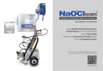
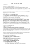
Product Testing by using : TL205
TL 205 generates specific UV/IR radiations which can be detected by Rezontech Flame
detector series as fire. It has an individual built in internal power supply hence, it can be
moved and used easily. It can be continuously working up to 30 minutes. For more
details kindly refer to the user manual.
※ If everything is fine without any problem during the testing period by using the test
lamp, the flame detector will generate actual fire alarm signal which can activate all
related fire fight system, so appropriate preparation and inspection must be placed before
the test with TestLamp.
Document No. Manual-2000X Rev.2
March 2012
- 28 -
Co.,Ltd.
UV/IR Type Flame Detector
RFD-2000X
[Figure 20] TL205 TEST LAMP
ㆍ Testing Sequences with TL205
1. Please wait for 10seconds after the power is supplied. Check, Yellow LED blinking.
2. Face and 'Turn On' the TL 205 in front of the flame detector.
3. The recommended distance between test lamp and product shall be within 5M
when point no. 2 above is performed.
4. If "Red LED" is lighting on the flame detector, fire is detected generally.
5. If the product is set to be recovering manually, the recovery will be start by
turning OFF/ON of the power supply
6. If "Red LED" does not light on during the test stage 2,3, please adjust the distance
and re-test again. If the same problem persists and even after the TestLamp is in
good conditions after the inspection (as per below stated), please contact the
manufacturer or A/S center. The flame detector might have defects.
Power supply
status checking
Scope of Inspection
- TestLamp's No.1 or No.2 lamp is not functioning, it means the
TestLamp is defected.
- If TestLamp's lamp No.1 is blinking and the radiation intensity is
weak, or if it's No.2 lamp is not functioning, please re-charge the
TestLamp.
[Table 23] Lighting Status of Test lamp
Product Operation Status Vary According to Testing Conditions
Status
Operate or Output Status
Before inserting
- Fault Relay signal Open (Normally Open : De-Energized)
power supply
Inserting
After
power
- All LED OFF
- Fault Relay signal Closed (Normally Closed : Energized)
inserting
power
supply
supply
Normal
Fire
- After 7 seconds of self-diagonosis test, LED intersect for
3seconds (Yellow → Red → Yellow......) blinking
- All output, "normal" signal output (Normally Closed : Energized)
- YELLOW LED blinking 0.5Hz
- All output "Fire" signal
[Table 24] Product Operation Status Vary According to Testing Conditions
Document No. Manual-2000X Rev.2
March 2012
- 29 -
Co.,Ltd.
UV/IR Type Flame Detector
RFD-2000X
5. Maintenance and Troubleshooting
This chapter deals with preventive maintenance, describes possible faults in detector
operation and indicates corrective measures. Ignoring these instructions may cause
problems with the detector and may invalidate the warranty. Whenever a unit requires
service, please contact rezontech or its authorized distributor for assistance.
5.1
Tools of Maintenance and Products Training
Basic tools are necessary and the person in-charge shall received products training in
order to maintain the detector. The setting issues and its related issue, regulations shall
be well trained or familiar with.
5.2
Maintenance Procedures
5.2.1 Clean the detector
The detector must be kept as clean as possible. Clean the viewing window and the
reflector of the Flame Detector periodically. The frequency of cleaning operations depends
upon the local environmental
conditions and specific applications. the early fire detection
system designer or fire fight system designer can give his/her personal recommendation.
1
2
3
5.2.2
Disconnect power to the detector before proceeding with any maintenance
including window/lens cleaning.
Use detergent liquid for view window on detector, and must rinse it with clean
water.
Where dust, dirt or moisture accumulates on the window, first clean it with a soft
brush. and use detergency soft optical cloth. and then rinse it with clean water.
Periodic Maintenance Procedures
The cleaning for prevention must be performed from time to time. And the operation test
must be also performed every 6 months. This test must be performed after the output
signal was blocked.
5.2.3
Maintenance Recording
Please record the maintenance process for the detector in the maintenance book. Device
name, date of installation, name of supplier and other necessary information must be
recorded accordingly. If there are any service needed, the maintenance record should be
sent together to the respective parties for reference.
Document No. Manual-2000X Rev.2
March 2012
- 30 -
Co.,Ltd.
5.3
UV/IR Type Flame Detector
RFD-2000X
Troubleshooting
If there is any error, kindly refer to the solutions as stated below. And please contact the
manufacturer or authorized A/S center if the problem proceed.
5.3.1
The LED is not responding after the power supply is connected.
ㆍ Check the product is combined rightly or not.
ㆍ Check the product is connected with the appropriate power supply polarity.
ㆍ Check the power supply connection to the product is within the proper voltage
range or not.
ㆍ Check the internal short occurs due to the foreign substance.
5.3.2
Yellow LED blinking (2Hz)
ㆍ Check the input voltage of the product. Check the operation range.
ㆍ The product connector might be polluted by foreign substances during the combination.
Please check the internal connector.
ㆍ If input voltage is appropriate, please contact the manufacturer or authorized A/S
center. Because the defect is caused by internal operating voltage or fire detection
circuit.
5.3.3
When the receiver is unable to detect various signal
ㆍ Check the product is combined rightly or not.
ㆍ Check whether the wiring connection is right or not, according to the user manual.
ㆍ All fire related signal can be measured right after the fire signal's detection.
Check the signal is measured or not after the fire signal.
ㆍ Check the electrical wiring is cut off or well connected.
ㆍ Check the jumper setting for 4~20mA current output is correctly set or not.
Document No. Manual-2000X Rev.2
March 2012
- 31 -
Co.,Ltd.
UV/IR Type Flame Detector
RFD-2000X
6. Customer Support
6.1
Contacts Information
Rezontech Office
Address
Phone, Fax, E-Mail
South Korea
TEL : +82-1544-9108
805, Megavally, Gwanyang-dong,
Dongan-gu, Anyang-si, Gyeonggi-do,
Korea
FAX : +82-31-420-0800
E-Mail : [email protected]
[Table 25] Information of Contact
Document No. Manual-2000X Rev.2
March 2012
- 32 -
Co.,Ltd.
UV/IR Type Flame Detector
RFD-2000X
7. Appendix
7.1
Abbreviation
Abbreviation
Description
ATEX
Atmosphere Explosives
AWG
American Wire Gauge
EOL
End Of Line
FOV
Field Of View
IECEx
International Electrotechnical Commission Explosion
IR
Infrared
UV
Ultraviolet
Latching
Refers to relays remaining in the ON state even after the ON condition
has been removed
LED
Light Emitting Diode
mA
Milli Ampere (0.001 ampere)
N.C
Normally Closed
N.O
Normally Open
[Table 26] Various Types of Abbreviation
7.2
Choosing of Wiring
Kindly consider the electric wiring standard as stated below during the product wiring.
7.2.1 Standard Chart for Power Supply Electrical Wiring during setting
(AWG Standard)
AWG #
㎟
24
Max. Resistance Value at 68°F (20℃)
Ohm per 100m
Ohm per 100ft
0.16 ~ 0.24
11.22
3.42
22
0.30 ~ 0.38
5.60
1.71
20
0.51 ~ 0.61
3.50
1.07
18
0.81 ~ 0.96
2.20
0.67
16
1.22 ~ 1.43
1.40
0.43
14
1.94 ~ 2.28
0.88
0.27
12
3.09 ~ 3.40
0.55
0.17
[Table 27] Standard of Electrical Wiring
Document No. Manual-2000X Rev.2
March 2012
- 33 -
Co.,Ltd.
7.2.2
UV/IR Type Flame Detector
RFD-2000X
Things to be consider when choosing electrical wiring for power supply:~
ㆍ The number of product to connect to one circuit
ㆍ Wiring length for installation (overall space or partly space)
ㆍ The necessary voltage range for product
ㆍ The minimum range of power supply voltage
ㆍ Setting of electrical wiring in order for the product to function
ㆍ Ambient temperature
7.3
Certification
ㆍ FM 3260 May, 2010
ㆍ ATEX CE1725 Ex II G, Ex d IIB+H2 T6 ( -40℃ ≤Ta ≤ +75℃ )
Document No. Manual-2000X Rev.2
March 2012
- 34 -