1
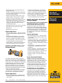
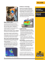
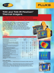
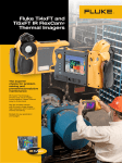
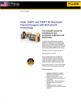
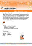
Thermal Imaging
Distributor
Training
Program
Product Knowledge
Thermal Imaging
Thermal Imaging is the science
of using thermal cameras to help
us locate problems in their early
stages, often before they can be
seen or found in any other way.
What is infrared thermography?
Non-contact infrared imagers provide fast, safe,
accurate measurements for objects that are:
• Moving or very hot
• Difficult to reach
• Impossible to shut-off
• Dangerous to contact
• Where contact would damage, contaminate
or change temperature
Product
Knowledge
Thermal
Imaging
Discovery of the infrared spectrum
Thermal cameras are instruments that create
pictures of heat rather than light. They
measure infrared (IR) energy and convert the
data to corresponding images of temperature.
A temperature difference, usually an abnormal hot spot, is typically associated with a
problem due to high electrical resistance or
excessive friction.
On March 13, 1781, while scanning the skies
with a 7-inch reflecting telescope, Friedrich Wilhelm Herschel, better known as Sir
William Herschel (1738 – 1822), observed an
unusual object. Thinking he had discovered
a comet, it soon became
apparent he was looking at
a planet never before seen,
Uranus. In his continuing
search for an optical filter
material to reduce the sun’s
image in telescopes during
solar observations, he
discovered infrared radiation.
By passing sunlight through
a prism and holding a thermometer just
beyond the red end of
the visible spectrum, he
observed a temperature
increase confirming the
existence of an invisible
form of light known today
as infrared wavelengths.
Heat transfer
The look, feel and operation of thermographic
cameras are similar to a digital camera with one
key difference, instead of CCD sensors (chargecoupled device); most thermal imaging cameras
today use microbolometer arrays. Their resolution is considerably lower than digital cameras,
commonly only 160 x 120 or 320 x 240 pixels.
When looking for a thermal imager, select one
that is fully radiometric. This means that each
pixel is recording temperature values, which
can be recalled later in software.
Page Fluke Corporation
FACT – Product Knowledge
When there is a temperature
difference between two
objects, or when an object
changes temperature, heat
energy moves from the
warmer areas to the cooler
ones until there is thermal
equilibrium.
Heat energy moves to
the surface, and then to
our camera, by a complex,
dynamic means that may
include: conduction, convection and radiation.
What you will learn
in this module:
• What is infrared
thermography?
• Discovery of the
Infrared Spectrum
• Heat transfer
• Thermal Imaging
Applications
Conduction is direct heat flow through mat-
ter resulting from actual PHYSICAL CONTACT.
wind blowing across a surface making it
appear cooler than its actual temperature.
Radiation is the transmission of electromagnetic rays through space at the speed of light
(186,000 miles/second) and like radio waves,
is invisible.
Product
Knowledge
Thermal
Imaging
For instance, if one end of an iron rod is heated, the heat travels by conduction through the
metal to the other end. Fourier’s Law (named
after the French physicist Joseph Fourier) describes this phenomenon, known as conduction heat transfer.
Each material that has a temperature above
absolute zero (-460°F) emits infrared radiation, including the sun, icebergs, stoves or
radiators, humans, animals, furniture, ceilings,
walls, floors, etc.
Convection is the transport of heat within a
gas or liquid.
Warm air, such as smoke, rises while colder air
sinks; the same is true for liquids, cold fluids
being less buoyant tend to sink. In addition, as
liquids evaporate, they draw heat energy from
their surroundings, something to keep in mind
when imaging a surface.
Newton’s Law of Cooling states that for a
body cooling in a draft (i.e., by forced convection such as the wind blowing), the rate of heat
loss is proportional to the difference in temperatures between the body and its surroundings.
A 10 mph wind can reduce the temperature
difference by up to 1/2. A 15 mph wind can
reduce the delta temperature by up to 2/3.
Bottom line, always consider the effect of
Page Fluke Corporation
FACT – Product Knowledge
Infrared radiation is just one form of electromagnetic radiation. Gamma rays, X-rays,
ultraviolet, visual light, and radio wave are
also forms of electromagnetic radiation.
The only difference among them is their
wavelength and the quantity of energy they
transfer.
The art of thermography involves an understanding of surface properties and their ability
to give up or reflect thermal energy.
Radiation is neither transmitted, absorbed,
or reflected perfectly by any material. Two or
three phenomena are occuring at once, and
together must add up to the whole.
As an example, we can see through a
window (transmission) but we can also see
reflections in the window at the same time.
We also know that glass absorbs a small
portion of the radiation because the sun heats
the glass itself. For a typical window, 90%
of the light radiation is transmitted, 7% is
reflected and 3% is absorbed.
The image of the iron shows a highly emissive dark coated surface on the left compared
to a highly polished surface on the right. The
apparant temperature of the coated side is
over 340°F, while the highly polished, reflective side appears to be under 135°F.
buss bars difficult. Emissivity depends on
factors such as surface material, temperature,
emission angle, and wavelength. Imaging
a surface below .6 emissivity is not recommended.
Product
Knowledge
Thermal Imaging Applications
Electricians and maintenance technicians
locate overheating joints and conductors,
a telltale sign of their failure, to eliminate
potential hazards. Building construction
technicians can see heat leaks, where thermal
insulation becomes faulty, to improve the
efficiencies of HVAC systems. Firefighters use
thermal imagers to see through smoke, find
persons, and localize hotspots of fires. Thermal imaging cameras are installed in many
luxury cars to aid the driver with thermal
detection in the dark to help avoid obstacles.
The coated side has higher emissivity than
the polished side. This means the coated
side has higher efficiency as a radiator than
polished reflective metal, and the metal
has higher reflectivity than the coated side
and is more efficient as an infrared mirror.
Thus, the coated side will indicate the target
temperature more closely. The polished metal
may indicate the background temperature, or
that which is reflected off the smooth surface,
rather than the actual temperature of the
surface of the iron.
This is an extremely important concept.
Thermographers see targets exhibiting this
emissivity contrast behavior every day. It
could be an insulated electric cable with a
bare metal lug connections or aluminum bus
bars. It could be a bare metal nameplate on
a painted surface such as an oil filled circuit
breaker or load tap changer. It could be a
piece of electrical tape placed by the thermographer on the bus bar to enable a decent
reading. The list is long.
Emissivity (e)
Emissivity is a measure of a material’s ability
to absorb and radiate energy. It is calculated
through the ratio of radiation emitted by a
surface to the radiation emitted by a known
material called a blackbody, at the same
temperature. A true black body would have an
e = 1, as close to a perfect emitter of thermal
energy, while any real object would have e
< 1. It is therefore a measure of a material’s
ability to emit infrared energy.
Materials are assigned an emissivity value
between 0 and 1.0. Most organic materials
such as paints, plastics, electrical tape, fabrics
and food have an emissivity value near 0.95.
The emissivity value of bare metals is considerably lower near 0 and considered thermal
reflectors. This makes measuring shiny
Page Fluke Corporation
FACT – Product Knowledge
Thermal
Imaging
Test your knowledge
Product
Knowledge
1. A temperature difference is typically associated with a problem due to _______
_____.
A. high electrical resistance
B. excessive friction
C. both A and B
D. neither A nor B
2. Heat energy moves to the surface, and then to the camera, by a complex, dynamic means that may include:
A. conduction, convection and osmosis.
B. metamorphosis.
C. conduction, convection and capacitance.
D. conduction, convection and radiation.
3. Conduction is direct heat flow ____________.
A. within a gas or liquid.
B. through matter resulting from physical contact.
C. through space at the speed of light.
D. None of the above
4. If an imager is ________________, each pixel is recording temperature values
that can be recalled later in software.
A. fully-radiometric B. automatic
C. parabolic
Thermal
Imaging
D. None of the above
1. C 2. D 3. B 4. A
Chapter Summary
What is Infrared Thermography?
• Thermographers use thermal cameras to help locate problems in their early stages, often before they
can be seen or found any other way
• A temperature difference, usually an abnormal hot spot, is typically associated with a problem due to
high electrical resistance or excesssive friction
• A thermal imager that is fully radiometric records values from each pixel, which can be recalled later in
software
Heat Transfer
• Heat energy moves from the warmer areas to the cooler ones until there is thermal equilibrium
• Heat energy moves to the surface, and then to our camera, by a complex, dynamic means that may
include: conduction, convection and radiation.
• Conduction is direct heat flow through matter resulting from actual physical contact
• Convection is the transport of heat within a gas or liquid
• Radiation is the transmission of electromagnetic rays through space as the speed of light
Emissivity and Reflectivity
• Emissivity is a measure of a material’s ability to absorb and radiate energy
• A true black body is close to a perfect emitter of thermal energy
• Materials are assigned emissivity values between 0 and 1.0
• Most organic materials such as paints, plastics, electrical tape, fabrics and food have an emissivity value
near 0.95
• The emissivity value of bare metals is considerably lower near 0 and considered thermal reflectors
Thermal Imaging Applications
• Electricians and maintenance technicians locate overheating joints and conductors, which often can be
indicative of bigger electrical problems
• Building construction technicians can see heat leaks, where thermal insulation becomes faulty, to
improve the efficiencies of HVAC systems
Page Fluke Corporation
FACT – Product Knowledge
Fluke.Not just infrared.
Infrared you can use.™
Fluke Corporation
PO Box 9090, Everett, WA USA 98206
For more information call:
In the U.S.A. (800) 443-5853 or
Fax (425) 446-5116
In Canada (800)-36-FLUKE or
Fax (905) 890-6866
Web access: http://www.fluke.com
©2009 Fluke Corporation. All rights reserved.
Printed in U.S.A. Phase 1, Module 4, Rev 2
Product Knowledge
Thermal Imaging
Find problems faster and
reduce unplanned downtime
with the ultimate tools for
troubleshooting, preventive,
and predictive maintenance
Fluke offers a complete range of handheld
thermal imagers, ranging from the popular
and affordable Ti10 and Ti25 to the highprecision Fluke IR FlexCam® Series that
delivers the largest and sharpest images in
the industry. The Ti25 and Ti10 thermal imagers are designed for everyday troubleshooting,
maintenance, and infrared inspection work
whereas the IR FlexCam Series is designed for
Predictive Maintenance (PdM) experts, process
engineers, and consultants who need the best
thermal imager available.
Electro-mechanical equipment
• Motors and pumps
• Bearings, pulleys and belts
Process monitoring
• Process control equipment
• Tanks, pipes, valves, steam traps and vessels
Facility maintenance
• HVAC systems
• Buildings and roofs
Built for the industry, Fluke Ti Series Thermal
Imagers can carry out inspections anytime,
anywhere and anyplace. In fact thermal imagers
can be used anywhere temperature plays an
indicating role. Some industry applications are:
Electrical power distribution systems
• Three-phase systems
• Overhead power cables
• Distribution panels
• Fuses, wiring and connections
• Power/utility
Page Fluke Corporation
FACT – Product Knowledge
Thermal
Imaging
Other
• Electronic design
• And many more
Ti25 and Ti10: The Ultimate tools
for troubleshooting and maintenance
The perfect tools to add to your problem
solving arsenal. Built for tough work environments, these high-performance, fully radiometric imagers are ideal for troubleshooting
electrical installations, electro-mechanical
equipment, process equipment, HVAC/R
equipment and others.
The solution for industrial
maintenance applications
Product
Knowledge
• Fluke Ti25 and Ti10 imagers come with
enhanced problem detection and analysis
capabilities with IR-Fusion® Technology.
Simply scroll through the different viewing modes quickly to better identify trouble
areas in Full IR thermal, picture-in-picture, or
automatic blend visual and thermal images.
• Optimized for field use in harsh work
environments.
• Engineered and tested to withstand a 2 m
(6.5 ft) drop—When was the last time you
dropped a tool?
• Withstands dust and water—tested to an
IP54 rating.
What you will learn
in this module:
• The product family
• Features and benefits
• IR-Fusion® Technology
• SmartView® IR analysis
and reporting software
• Delivers the clear, crisp images needed to
find problems fast.
• Identify even small temperature differences
that could indicate problems with excellent
thermal sensitivity (NETD).
• Intuitive, three-button menu is easy to use—
simply navigate with the push of a thumb.
• No need to carry pen and paper—record
findings by speaking into the camera. Voice
annotations can be recorded with every
image you take. Voice comments are saved
along with individual images for future
reference (Ti25 only).
• Everything needed to get started is included.
• Adjustable hand strap for left-or righthanded use.
• Manufactured in the U.S.A.
Typical applications:
• Preventive maintenance – Identify electrical
and mechanical problems before they cause
failure
• Industrial troubleshooting – Use infrared
to assist in the troubleshooting of system
failures or equipment performance issues.
• Process monitoring – Real-time observation
to ensure efficient and safe operation
• Power/ Utilities - inspection and analysis of
substation equipment and transformers
Ti40FT and Ti45FT IR FlexCam®
Thermal Imagers
• Industrial troubleshooting – Use infrared
to assist in the troubleshooting of system
failures or equipment performance issues.
• Quality control – Examine prototypes and
refine thermal management designs
• Process monitoring – Real-time observation
to ensure efficient and safe operation
Product
Knowledge
Ti50FT and Ti55FT IR FlexCam®
Thermal Imagers
Thermal
Imaging
The professional’s choice for applications
demanding the highest performance.
Choose the Fluke Ti5x models when you
need the best images. They feature 320 x
240 detectors with industry leading thermal
sensitivity (≤ 0.05 ˚C NETD) for high resolution,
ultra high-quality images. In addition, with a
60 Hz detector acquisition rate temperatures
are displayed live on the large 5-inch diagonal
color display.
Typical applications:
• Preventive maintenance – Identify electrical and mechanical problems before they
cause failure
• Predictive maintenance - trend equipment
performance with infrared inspections over
time to determine optimum maintenance
and repair schedules, minimizing uplanned
downtime
• Power/utilities – Inspection and analysis
of substations, transmission lines and
equipment
• Process monitoring – Real-time observation
to ensure efficient and safe operation
• Research and Development – Quantify heat
patterns to improve product designs
• Electronic design – Close up circuit board
analysis
Large, sharp thermal images
The Fluke Ti4x models feature everything
needed for virtually every thermography task.
With a 160 x 120 detector and a temperature
sensitivity to 0.08 °C (NETD) they deliver high
resolution images where even the smallest
temperature differences can be seen. The
units are extremely easy to use through the
Windows® CE menu structure and offer an
extended troubleshooting feature set to allow
on the spot analysis in the field.
NETD stands for Noise Equivalent Temperature Difference. Bottom line, the lower the
spec the greater the thermal sensitivity.
Typical applications:
• Preventive maintenance – Identify electrical and mechanical problems before they
cause failure
Page Fluke Corporation
FACT – Product Knowledge
Thanks to the largest display (five inch)
available on this type of thermal imager in
combination with low-noise VOx sensors, the
Fluke IR FlexCam units produce exceptionally high-quality images making even the
smallest temperature differences visible. This
is comparable with images normally only
obtained on far more expensive instruments.
A sharp image in every situation
The innovative 180° articulating lens makes
it possible to view and capture images in
areas with poor accessibility. The display
remains clearly visible while viewing over
high objects, under a machine or around
immoveable obstructions. The SmartFocus lens
simplifies getting a stable and sharp image.
IR-Fusion® Technology
Infrared and visible light images fused
together on one display See things both
ways—infrared and visual (visible light)
images fused together communicating critical information faster and easier—traditional
infrared images are no longer enough.
Fluke led the way in the development and
use of IR-Fusion and the industry followed.
Both visible and infrared images allow you to
communicate exactly where potential savings
can be gained. IR-Fusion is standard on most
Fluke thermal imager models.
Make anomalies visible
Thanks to built-in functions like AutoCapture,
the IR FlexCam Thermal Imagers help to
troubleshoot difficult problems. The instrument is easily set up to automatically capture
only those images where a temperature
limit is exceeded. This way, difficult to find
intermittent problems can be captured and
analyzed quicker by concentrating only on the
images containing the anomalies.
Analysis and reporting comes standard
The SmartView® software (supplied with the
unit) includes a complete range of infrared
image viewing, analysis, annotation and optimization tools. It even allows for the creation
of professional reports that can be customized
to accommodate specific company requirements like layout, formatting, and content.
Sharp, high-resolution thermal images
The Fluke IR FlexCam is available with different detector sizes, temperature ranges and
thermal sensitivities to meet every image
quality requirement.
All Fluke thermal imagers are fully radiometric. Measurement data for thousands of
individual sensor points are stored. All these
data points can be used for analysis and
reporting on the imager or in the software
supplied with each instrument.
5 viewing modes*
Full IR – For troubleshooting and analyzing equipment and installations with very
high resolution IR imaging. For detecting
the smallest temperature variations to track
down the origin of problems and fully
document the extent of remediation. Full
IR images are automatically linked to full
visible light images.
Picture-in-Picture – For creating an IR
’window’ surrounded by a visible light
frame to easily identify thermal anomalies,
while maintaining a frame of reference with
surroundings.
Alpha Blending – For combining visible and
infrared images together in any ratio to
create a single image with enhanced detail
that will help in precisely locating problems.
IR/Visible Alarm – For displaying only
temperatures that fall above, below, or in
between a specified range as IR image,
leaving the rest of the scene as a fully
visible light image.
Full Visible Light – A bright, detailed pixelfor-pixel reference image of subject areas
for documentation and reporting.
*Not all models have all viewing modes. Please consult
technical data sheets for specific information.
The real power behind IR-Fusion is the
SmartView® software. Capture and annotate
hundreds of corresponding visible and infrared
images in the field and quickly import them
into the SmartView suite. Here, the images can
Page Fluke Corporation
FACT – Product Knowledge
Product
Knowledge
Thermal
Imaging
be optimized for maximum communication
value—adjusting imagery within IR-Fusion’s
five display modes—perform sophisticated
analysis, and produce professional reports
quickly and easily. SmartView’s comprehensive reporting tools are fully customizable.
Fluke SmartView® IR analysis and
reporting software
Fluke SmartView software is included with
each Fluke thermal imager. This powerful software is a modular suite of tools that
annotates, views, optimizes and analyzes
IR images. It also generates fully customizable and professional-looking reports in a
few easy steps. The IR-Fusion® technology
is fully supported. The software is easy to
use for maintenance personnel, yet delivers
the performance specialized thermographers
require for advanced analysis and reporting.
Simplified report generation
• Generate professional customized reports
fast
• One-click report generation for a quick
result
• Choice of features including before/after, IR
plus visible light, annotations, supporting
data and graphics
• Report wizard guides the user through
report generation
“You don’t need to be a computer genius
to get the most out of SmartView software.”
Image viewing and editing
• Displays an array of open images for convenient selection and analysis
• A simple mouse click displays the temperature at any given point
• Color palettes, reference images, markers
and emissivity can be edited
Extensive annotation possibilities
• Add annotations to images in the camera or
in the PC software
• Input information such as locations, category and other notes
• Reference images can be linked together
for good/bad and before/after analysis
• Annotations can be included in reports
Detailed analysis and total image control
• Contrast and detail can be easily adjusted
to display more effectively by altering the
palettes and adjusting level span
• A complete set of marker tools are provided
(Hot, Cold, Center Point, Center Box, etc.)
• Five viewing modes enable image optimization based on application needs (IRFusion models only)
Page Fluke Corporation
FACT – Product Knowledge
Chapter Summary
Ti25 and Ti10 Thermal Imagers
The Ti25 and Ti10 thermal imagers are the most
rugged, reliable, and easy to use imagers in the
market today. Equipped with IR-Fusion technology,
they are the perfect tools for everyday industrial
and commercial troubleshooting and maintenance
activities.
They come with everything you need to get started
including:
• AC power supply/battery charger (including mains
adapters)
• 2GB SD memory card
• SD card reader (USB) for downloading images into
your computer
• SmartView® software with free software upgrades
for life
• rugged hard, carrying case
• soft transport bag
• hand strap
• users manual
• warranty registration card
• interactive training DVD
Product
Knowledge
Thermal
Imaging
Test your knowledge
Product
Knowledge
1. All Fluke imagers are _______________________________, the image and associated measurement data is stored
for later analysis.
A. fully radiotonic
B. fully radiometric
C. fully telemetric
D. fully radiomasonic
2. The Fluke Ti50FT and Ti55FT IR FlexCam® Thermal Imagers are the professional’s choice when demanding
the highest sensitivity because they feature:
A. 320 x 240 detectors
B. ≤ 0.05 ˚C NETD for high resolution
C. a 60 Hz detector acquisition rate
D. all of the above
Thermal
Imaging
3. IR-Fusion™ Technology _______________________________________________________.
A. links a real world visual image with a thermal image.
B. powers the instrument for years and years without batteries.
C. holds the instrument together instead of screws.
D. links voice recordings with thermal images.
4. Fluke SmartView™ IR analysis and reporting software is included with each Fluke thermal imager,
license free, with the purchase of each imager.
A. true
B. false
C. at an extra price
D. don’t know
1. B 2. D 3. A 4. A
Chapter Summary (continued)
Ti40FT, Ti45FT, Ti50FT, Ti55FT FlexCam Thermal imagers
The expert’s choice for problem solving and preventive/predictive maintenance.
The Fluke Ti5xFT and Ti4xFT models feature everything needed for virtually any thermography task. All
Fluke FlexCam Thermal Imagers come standard with the patent-pending Fluke IR-Fusion® Technology
fusing visual (visible light) images with infrared images.
• SmartView™ IR analysis and reporting software is included with each purchase along with free software
upgrades for the life of your product.
• The Ti4xFT models feature 160 x 120 detectors and temperature sensitivity (NETD) down to 0.08 °C (80 mK)
in the higher end model.
• The Ti5xFT models feature 320 x 240 detectors and temperture sensitivity (NETD) down to 0.05 °C (50 mK)
in the higher end model.
Choose Fluke FlexCam Thermal Imagers when you need industry leading thermal sensitivity for high resolution, ultra high-quality images. They come with everything you need to get started, including:
• Heavy duty carrying case
• 2 rechargeable battery packs
• battery charger
• ac adapter (for Ti45FT and Ti55FT only)
• video cable
• 1 GB compact flash card
• compact flash card reader and USB cable
• neck strap
• printed getting started guide
• SmartView reporting and analysis software on CD
• complete user manual on CD
Page Fluke Corporation
FACT – Product Knowledge
Fluke.Not just infrared.
Infrared you can use.™
Fluke Corporation
PO Box 9090, Everett, WA USA 98206
For more information call:
In the U.S.A. (800) 443-5853 or
Fax (425) 446-5116
In Canada (800)-36-FLUKE or
Fax (905) 890-6866
Web access: http://www.fluke.com
©2009 Fluke Corporation. All rights reserved.
Printed in U.S.A. Phase 3, Module 8, Rev 2
Fluke.Keeping your world
up and running.®
Fluke Corporation
PO Box 9090, Everett, WA USA 98206
Fluke Europe B.V.
PO Box 1186, 5602 BD
Eindhoven, The Netherlands
For more information call:
In the U.S.A. (800) 443-5853 or
Fax (425) 446-5116
In Europe/M-East/Africa +31 (0) 40 2675 200 or
Fax +31 (0) 40 2675 222
In Canada (800)-36-FLUKE or
Fax (905) 890-6866
From other countries +1 (425) 446-5500 or
Fax +1 (425) 446-5116
Web access: http://www.fluke.com
©2009 Fluke Corporation. Specifications subject to
change without notice. Printed in U.S.A 1/2009
FACT Distributor Training Program C-EN-N Rev A