1
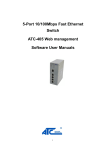
8-Port 10/100Mbps Fast Ethernet
Switch
ATC-408 Web management
Software User Manuals
http://www.szatc.com
Contents
1
2
3
4
Administrator........................................................................................................ 3
1.1
Authentication configuration...............................................................7
1.2
System IP Configuration.....................................................................7
1.3
System status.......................................................................................9
1.4
Load default setting........................................................................... 11
1.5
Firmware update................................................................................13
1.6
Reset device.......................................................................................14
Port Management.............................................................................................. 15
2.1
Port configuration...............................................................................15
2.2
Bandwidth Control............................................................................. 16
2.3
Broadcast Storm Control.................................................................. 19
2.4
Max Packet length............................................................................. 21
VLAN Setting......................................................................................................24
3.1
Multi to 1 Setting................................................................................ 24
3.2
Tag Based VLAN............................................................................... 26
3.3
Port based VLAN............................................................................... 32
QoS Setting........................................................................................................ 33
4.1
Class of Service Configuration........................................................ 33
4.2
High Priority Queue Configuration.................................................. 34
4.3
Customization DiffServ..................................................................... 36
5
Port Security....................................................................................................... 40
6
Configuration Backup/Recovery......................................................................41
7
Logout..................................................................................................................45
8
Appendix Hyper Terminal Authentication....................................................... 46
1 Administrator
A. PC NIC setting
Start→Control Panel
Choose Internet Connection
3
Choose the Properties of Local Area Connection by clicking the right side of
the mouse.
Choose Internet Protocol (TCP/IP)
4
Use the following IP address:
IP address:192.168.2.X (X:1~254)
Subnet mask :255.255.255.0
Check switch IP address
Start→Run→cmd ping 192.168.2.1 –t
5
<enter>
B. Login
Default IP : 192.168.2.1
Login ID :admin (Lowercase)
Password :system (Lowercase)
If you input error ID, the following screen will appear.
C.
Welcome to 8 Port Smart Switch Web Controller
6
1.1 Authentication configuration
(Username & Password max:15 & can only use a-z","A-Z","0-9","_","+","-","=".)
1.2
System IP Configuration
Default IP:192.168.2.1
The following screen is the example of changing the IP address to
7
192.168.2.5.
IP
address, Subnet Mask, and Gateway at system IP Configuration diagram box
can be configured by user. IP178C/IP178CH also supports DHCP methods to
get IP address from DHCP server.
Login in new IP address 192.168.2.5
8
1.3 System status
This page is used to check the status of switch, including Switch MAC address
and software version.
The MAC address and version of .ATC-408 will be shown at system status
diagram box. Comment field can accept Aa~Zz, excluding special character.
A. Comment:
It is a nickname of the management switch you can set.
9
B. Idle Time Security:
It is an AUTO logout timer and the idle time range is
1~30 Minutes. If select Auto Logout and click update without filling in the idle
time blank, then the idle time will be default value.
Select Auto Logout (Default).
When idle time expires, following notice will appear.
Select Back to the last display.
Without any actions on this system, back to login screen will appear.
C. MAC address setting
The internet address, http://192.168.2.1/MACIDFix.htm, helps user to modify
10
MAC address setting.
For example:
MAC Address, 50:80:17:80:13:F0, is modified as following, 50:80:17:80:13:F1.
Click Update to get the new MAC address.
1.4 Load default setting
Clicking the “Load default setting” button will make the switch being set to the
11
original configuration.
Note: this change only concerns the switch behavior, excluding the change for
user name, password and IP configuration.
After Completing load process, the “System Setting Saved!!” will appear. Then
press “Reset Device” to take effect.
12
1.5 Firmware update
After pressing firmware update button, the switch will erase the older version
flash code first. Then enter file name at specific path, and the update will be
completed.
Enter password to execute firmware update process.
After pressing “Update” button, the old web code will be erased.
13
Enter correct path and press “UPDATE” button to complete firmware update
process.
Firmware update is finished.
1.6 Reset device
This page is used to reset device.
14
Press “Confirm” button to take effect for rebooting device.
2 Port Management
2.1 Port configuration
This page allows the user to configure operating mode of the physical port.
15
After completing the settings, press “Submit” button to take effect.
SMB status
After completing the settings, click update button to take effect. The setting will
be reflected at current status window.
2.2 Bandwidth Control
The range of bandwidth is from 128K to 8M, Full speed.
Example :
Set Port1→128K、Port2→256K 、Port3→512K 、Port4→1M、Port5→2M 、
Port6→4M 、 Port7→8M 、Port8→Full
16
Results :
Results :SMB setting :100M Full,120m,60 length ,random data
17
18
2.3 Broadcast Storm Control
IP178C/IP178CH drops the incoming packet if the number of broadcast packet
in queue is over the threshold.
19
SMB setting:
Results:
A Broadcast Storm Control = Disable
B Broadcast Storm Control = Enable
20
2.4
Max Packet length
Two kinds of max packet length, 1536 / 1552 Bytes
A Packet Length (Bytes):1536(default)
SMB setting: set length 1532 bytes because CRC packets occupy 4 byte.
21
Following chart shows packet length.
Oversize packet length will appear in Oversize column.
22
B Packet Length (Bytes):1552
SMB setting: set length 1548 bytes because CRC packets occupy 4 byte.
Following chart shows packet length.
Oversize packet length will appear in Oversize column.
23
3 VLAN Setting
3.1
ulti to 1 Setting
Enable Multi to 1 setting will force Tag Based VLAN and Port Based VLAN
function to be disabled.
Set a specific port as an exporting port. Other ports can’t transmit and receive
packets and only the destination port can.
24
Example:
Set port 3 as the destination port. When port 0~port 7 transmit packets, only
port 3 will receive packets. SMB setting: 100M Full / Flow control=ON
Port 1~port 8 transmit packets in turn and only port 3 will receive packets.
Port 3 transmits broadcast packets and Rx Bytes of port 1~port8 (excluding
port 3) receive packets from port 3.
25
3.2 Tag Based VLAN
Tag Based VLAN function can’t be enabled unless turning off Multi to 1 setting
and Port Based VLAN function, meaning load default setting.
Enable Tag Based VLAN function before use, or warning message will appear.
A Set Add Tag / Don’t Care / Remove Tag function for port 1~port 8.
(Note: Please don't add VLAN tag on your control port)
Setting as following:
26
Example 1:
SMB setting: Port 8 transmits packets with VLAN Tag.
Example 1 results:
27
Example 2:
SMB setting: Port 7 transmits packets without VLAN Tag.
28
Example 2 results:
B PVID Index Setting
This setting must match VLAN Member setting
Set the PVID index of port 1~port 8 and the value is 1~15.
The set results will show as following.
29
Example 1:
Set 9 as the PVID index value of port 5.
Port 5 transmits packets without VLAN Tag.
(Length Random / Background Random / DA=Broadcast, SA=05)
The result is that ports in VLAN Member 9 will receive the packets from port 5.
Example 2:
Set 9 as the PVID index value of port 1.
Port 1 transmits packets with VLAN Tag.
(Length Random / Background Random / DA=Broadcast, SA=01 / Type
data=8100 0009)
The result is that ports in VLAN Member 9 will receive the packets from port 1.
Capture the transmitted packets and know their type data is 8100 0009.
30
C VLAN Member
IP178C supports 15 sets of VLAN Group. Member ports in the same VLAN
Group can transmit and receive packets from each other but non-member
ports can not.
Following chart shows VLAN Member setting.
31
Example:
SMB setting: Length Random / Background Custom / DA=Broadcast, SA=01
Set port 1, port 2, and port 3 in the same VLAN. When port 1 transmits packets,
only port 2
and port 3 will receive the packets.
3.3 Port based VLAN
Port Based on LAN function can’t be enabled unless turning off Multi to 1
setting and Tag Based VLAN function, meaning load default setting.
Setting VLAN Member for port 1~port 8.
32
Example: Set port 1, port 2, and port 3 in the same VLAN. When port 1
transmits broadcast packets, only port 2 and port 3 will receive the packets.
4 QoS Setting
4.1 Class of Service Configuration
High priority is a special channel, which can make important packets pass
through quickly.
Each port must set high priority by selecting its port base or VLAN Tag/IP/DS.
Example: Select Port Base for port 1 and this means that port 1 is set high
priority.
33
4.2 High Priority Queue Configuration
The setting in High Priority Queue Configuration must cooperate with Class of
Service Configuration through selecting VLAN Tag/IP/DS.
Weight-Round-Robin Mode sets packets High priority and Low priority, the
proportion is 4(8):1.
Example:
Set port 5 and port 6 transmit packets to port 7.
34
SMB setting:
Capture port 7 packet data and check MAC src column. Find that the
proportion of port 5 (High Priority) and port 6 (Low Priority) is 4:1.
35
Capture port 7 packets and check MAC src column. Find that the proportion of
port 5 (High Priority) and port 6 (Low Priority) is 8:1.
4.3 Customization DiffServ
Set DiffServ value of IPv4/IPv6 DiffServ frame format in High Priority.
The setting in Customization DiffServe must cooperate with Class of Service
Configuration through selecting VLAN Tag/IP/DS.
Example: Select the VLAN Tag/IP/DS for port 1 and therefore port 1 is set High
Priority.
36
* IPv4/IPv6 DiffServ frame format
Select index=3 as IPv4/IPv6 DiffServ value, and 3 (hexadecimal) equals
000011 (6 bit).
37
SMB setting:
I. IPv4 DiffServ
Reference IPv4/IPv6 DiffServ frame format, and then the value is 0100
0000 0000 1100 (2Byte). Therefore, 0800 400C (4 Byte) is the content of IPv4.
38
II. IPv6 DiffServ
Reference IPv4/IPv6 DiffServ frame format, and then the value is 0110
0000 1100 0000 (2Byte). Therefore, 86DD 60C0 (4 Byte) is the content of IPv6.
Left frame (in red) shows that WRR is 4:1.
Right frame (in blue) shows the content of IPv4.
Left frame (in red) shows that WRR is 4:1.
Right frame (in blue) shows the content of IPv6.
39
5 Port Security
Enable this function will make ports unable to transmit and receive packets.
Note: Please don’t enable port security on your linking port.
Example: Enable port 1 and port 2.
Use SMB to do Ring test and port 1 and port 2 won’t receive packets.
40
6 Configuration Backup/Recovery
This function can read/write EEPROM.
Authentication method:
Step 1 、Set port 1=Forced 100Mb FULL, port 2=Forced 10Mb FULL. Then
plug power cord and enter the same web page for ensuring the new setting
take effect.
41
Step 2 、 Enter Configuration Backup/Recovery web page, and then choose
Download in Backup(Switch->PC) column for saving this setting.
Step 3 、Save the setting and the file name is x.bin
42
Step 4 、Choose the image file, enter password, and click Update shown in
Recovery(PC->Switch) column for reading EEPROM.
Step 5 、Click Reboot to use new setting to login.
43
Step 6 、Enter following web page and know this new setting takes effect.
44
7 Logout
Choose Logout
Exit web page will appear for further confirmation.
Click YES will leave this system. Click NO will back to this system.
Click YES will close the web page. Click NO will back to the login web page.
45
8 Appendix Hyper Terminal Authentication
Step
1
Start→
All
Programs→
Accessories→
Communications
HyperTerminal
Step 2 、Enter a name and choose an icon for the connection
Step 3 、Connect using: Choose COM1
46
→
Step 4 、COM1 roperties :
Bits per second :19200
Flow control:None
47
Step 5 、Use Hyper Terminal to authenticate Web Code Version: V2.21
48