1
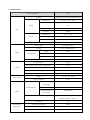
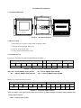
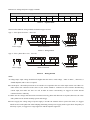
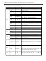
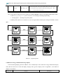
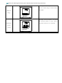
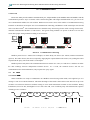
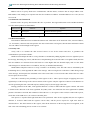
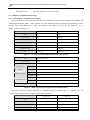
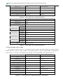
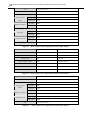
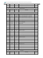
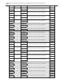
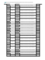
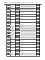
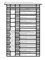
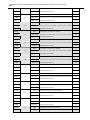
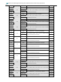
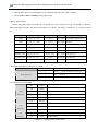
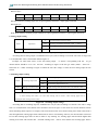
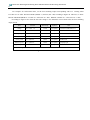
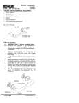
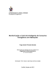
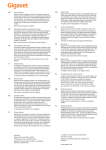
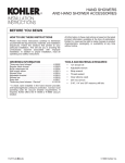
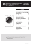
PD76-24E-WFF
Digital Indicating Panel Mounted Electrical Measuring Instruments
User Manual
Table of Contents
I.Introduction............................................................................................................................................................. 3
1.1 General........................................................................................................................................3
1.2 Technical data.............................................................................................................................4
II.Outline & Installation ........................................................................................................................................... 7
2.1 Installation Dimension...............................................................................................................7
2.2 How To Install.............................................................................................................................7
2.3 Terminals Layout .......................................................................................................................7
Ⅲ。 Operation Instruction...................................................................................................................................... 9
3.1 Nameplate ...................................................................................................................................9
3.2 Display.........................................................................................................................................9
3.3 Program operation ...................................................................................................................10
3.4 Multi-rate energy and demand message inquiry ..................................................................12
IV. Communication.................................................................................................................................................. 14
4.1 Forward.....................................................................................................................................14
4.2 Byte format ...............................................................................................................................14
4.3 Frame Format ..........................................................................................................................15
4.4 Error management.................................................................................................................17
4.5 Samples of Communication message...................................................................................18
Appendix .................................................................................................................................................................. 21
I.Introduction
1.1 General
PD76-24E-WFF Digital indicating Panel Mounted Electrical Measuring Instrument is designed for the electrical
monitoring for utilities, industrial mining corporations, intelligence towers and communities. It adopts large scale IC,
digital sampling technology and SMT technology. It can measure all the common electrical parameters with high
accuracy, such as three-phase voltage, three-phase current, active power, reactive power, frequency, power factor,
active energy, reactive energy and four quadrant energy. It is capable of multi-tariff function (10 time segments,4
rates). The durable LED displays the parameters measured and the performance information of electrical network
system. With high speed RS485 communication port and conformance to the Modbus protocol. There are four
programming pushbuttons in the faceplate, it is very convenient for users to achieve switching display and meter’s
parameters program setup at site, with high flexibility.
There are many extended functions to choose, for instance, the function of 4 analog(0~20mA/4~20mA )
output is for energy and electricity transportation output, and the function of 4 switching input and output is for local
or remote switching signal monitoring and control output ( “remote communication” and “ remote control” function).
PD76-24E-WFF with excellent performance and reasonable price, it can replace the normal electricity
transportation instrument, measurement indicating meter, energy measuring meter and other related accessorial
units.
PD76-24E-WFF can be used widely for energy management system, transformer substation automatization,
switching network automatization, industrial automatization, intelligence buildings, intelligence switchboards and
switch cabinets, it is characteristic of convenient installation, simple wiring, easy maintenance, and less works. It also
can be connected with PLC and industry control computers.
1.2 Technical data
Technical Parameters
value
Network
Three-phase three-wire, three-phase four-wire
Rated voltage
Overload
AC 100V, 220V,
lasting:1.2 times
momentary:double times
Voltage
/30s
Input
Power consumption
<0.5VA(per phase)
Resistance
>500KΩ
Rated current
AC 1A 、5A
Current
Overload
Resistance
lasting:1.2 times
momentary:20 times/1s
<20mΩ(per phase)
Frequency
45~65Hz
Energy impulse
Two impulse output
Constant
Active:10000imp/kwh
Reactive:10000imp/kvarh
Mode
RS-485
Protocol
MODBUS-RTU/ASCII
Baud rate
1200、2400、4800、9600
Output
Communication
Accuracy
400V
Display
LED
Voltage,current
±0.2%
Active power, reactive power, apparent power
±0.5%
Frequency
±0.2%
Active energy
±0.5%
Reactive energy
±2%
Range
Power supply
AC、DC
Power consumption
Input and auxiliary
80~300V
<5VA
>2KV50Hz/1min
power supply
Voltage endurance
Security
Input and output
>2KV50Hz/1min
Output and auxiliary
>2KV50Hz/1min
power supply
Insulated resistance
Input, output and auxiliary power supply
against the watchcase >100MΩ
Case anti-fire
V0
Electromagnetic
Electrostatic discharges
±15KV
compatibility
Fast transient burst
±4KV
Electromagnetic RF fields
80MHz~1000MHz
10V/m
Ambient
temperature
Temperature
Operation :-10~60℃,
Storage :-25~70℃
Humidity
≤95%RH,(without dew, corrosive gas)
Altitude
≤3000m
II.Outline & Installation
2.1 Installation Dimension
117.0
106.5
12.5
120.0
110.0
120.0
119.0
Picture 1 Installation Diagram
2.2 How To Install
① Drill a hole (size:111mm×111mm) in the switching cabinet
② Take out the meter,clamps and screws.
③ Insert the meter into the hole
④ Fix the clamps and fasten the screws
2.3 Terminals Layout
Upper row:Current, test and communication terminals
Current terminals
*1
2
*3
IA
Test terminals
4
*5
IB
6
7
IC
RS485
8
9
10
11
12
P+
Q+
P- Q-
A
B
Picture 2 Current, test and communication terminals
Note:
Note:“P+”
P+”—active impulse output positive
“Q+” — reactive impulse output positive
“P-”—active impulse output earthed
“Q-”— reactive impulse output earthed
Middle row:
:Input and output terminals
Output terminals
+25
OUT1
26
+27
28
OUT2
+29
Switching output terminals
30
DOUT3
+31
OUT4
32
33
34
35
36
37
IN1
IN2
IN3
IN4
COM
38
Picture 3 Input and output terminals
Note:According to the type of meter, there are two kinds of output terminals: switching output terminals and
analog output terminals
COM—switching input earthed
Bottom row: Voltage and power supply terminals
Voltage terminals
13
14
15
UA
UB
16
17
Power supply
18
19
UC
20
21
UN
Picture 4
L
22
23
24
N
Signal terminals
The meter has different wiring methods for different types of load
Type 1:three-phase four-wire,three CTs.
L
N
Power supply
Direct connection
Picture 5
PT operated
Wiring method
Type 2:three- phase three- wire,two CTs。
L
N
Power supply
Direct connection
PT operated
Picture 6 Wiring method
Note:
:
A. Voltage input: input voltage should not be higher than the meter’s rated voltage(100V or 400V), otherwise, it
should adopt PT, and 1A fuse is required.
B. Current input:the rated input current is 5A.outside CT is required in the case of the input current >5A.if there are
other meters also connected to the same CT, the meters should be connected in series. Before disconnecting
current input, first make sure the CT is off. In order to remove conveniently, we suggest use socket instead
connected to the CT directly.
C. Make sure the voltage and current line connected correctly, phase and direction in sequence,otherwise, the value
and symbol can’t be shown normally (power and energy) .
D. Power supply. the voltage range of power supply is AC/DC 80~270V.In order to protect the meter, we suggest
install 1A fuse for the phase line when adopting alternating current power supply. In the region where the quality of
electricity is poor, we suggest use surge suppresser and fast impulse suppresser.
PD76-24E-WFF Digital Indicating Panel Mounted Electrical Measuring Instruments
9
Ⅲ。 Operation Instruction
3.1 Nameplate
Time period
Switching
Input
+
Quadrant
Switching
Output
z
LCD
H
Pushbutton
Picture 7.Nameplate
3.2 Display
By setting the DCW(display control word)to program display modes. Or push“◄”,“►”to switch display
mode manually, it will return to previous display mode after 30 seconds.The details of the display modes as
following:
Display Mode
Example
0
-
Description
Automatic circle display 5 modes
Displays three phase voltage, UA UB UC(three
+
phase four wire) or UAB UBC UCA(three phase
three wire) and positive active energy
1
The picture left is displaying Ua is 220.6V,Ub is
219.7V,Uc is 220.3V, positive active energy is
334.15 kWh.
Displays three phase current and opposite active
+
2
energy.
The picture left is showing Ia is 100.2A,Ib is
101.1A,Ic is 96.5A, opposite active energy is
196.03 kWh.
PD76-24E-WFF Digital Indicating Panel Mounted Electrical Measuring Instruments
10
Display Mode
Example
Description
Displays active power, reactive power, power
factor and positive active energy.
+
The picture left is showing active power is
3
163.03kW, reactive power is 81.5kvar,,positive
reactive energy is 72.68kvarh
Displays voltage of the back-up batter, frequency
+
and opposite reactive energy.
The picture left is showing frequency is 50.02Hz,
z
4
opposite reactive energy is 26.35kvarh
H
Displays the time and date
The picture left is showing time is 12:24:38, date
+
is 2005-01-01
5
i ure
ispla mode
3.3 Program operation
Under program operation, the meter provides menu for setup, input, communication, and analog output. Use
LED displays hierarchical management: the first line displays first layer menu information, the second line displays
the second layer menu information, the third line displays the third layer menu information.
The functions of the four pushbuttons are as the follows:
“MENU”
:When the meter under measurement display mode, the pushbutton is for entering program mode.
Press it, the meter will ask user to input password, programming and setting is available only after entering correct
password. During programming, this pushbutton is for returning to upper menu.
“◄”and“►”
:When the meter under measurement display mode, these two pushbuttons are for circle display
manually. During programming, they are for making the menu forth/back or the number increase/decrease. When
inputting number, press it to increase/decrease the number quickly, or push “◄”or“►” together with “←┘”
or “MENU” to change the number as 10 or100.
“←┘”
:When programming, the pushbutton is for confirming the modification and returning to upper menu.
When displaying voltage, press it to switch displaying phase voltage and line voltage.
When return from programming mode to measurement display mode, the meter will show “save yes” to remind
user if any parameter has been modified, press “menu” to quit without saving the settings. If you want to save the
settings, then press “←┘”. When restore the system as factory settings, the settings will effect directly, so it should
PD76-24E-WFF Digital Indicating Panel Mounted Electrical Measuring Instruments
11
be very carefully when restore system, so that to avoid losing data.The menu’s structure is as follows, users can set
the proper parameters as per their own requirements.
First layer
Second layer
PSUD
SET
INPT
-
Description
8888
Input password, only valid password can enter program
DISP
0-5
Set display control word
LIGT
3 modes
Backlight control modes:AUTO,ON,OFF。
BRT
1-16
Adjust display brightness,1-darkest,16-brightest 。
TURN
1-99
Turning time, it effects when DISP set as 0.
DATE
YYYY.MM.DD
TIME
HH:MM:SS
ROLL
1-15
SOUT
0-1
CLR.E
YES
After confirmation, reset the energy and demand data to zero
D.CLR
YES
After confirmation, reset the demand data to zero
RSET
YES
After confirmation, reset the system parameters as factory’s setting
nET
n.3.4 or n.3.3
Electrical network type: 3P3W, 3P4W
1-9999
Voltage variation
1-9999
Current variation
ADDR
1-247
Meter Modbus communication address
BAUD
1200-38400
Baud rate 1200、2400、4800、9600、19200、38400。
DATA
3 format
NONE、ODD、EVEN。
PROT
RTU/ASCII
2 communication modes:Modbus-RTU、Modbus-ASCII。
RAT.U
RAT.I
CONN
Third layer
1
1
Date setting, in this mode, the current item will flash when setting,
push “◄”or“►” to increase/decrease the item
Time setting, in this mode, the current item will flash when setting,
push “◄”or“►” to increase/decrease the item
Step time, unit: minute
Second signal/reactive energy pulse output select (0-output second
signal,1-second signal)
analog output setting, under item parameter 1, choose electric energy
Item parameter
AO-x
1
AOSIx
Item parameter
2
AOSx
parameter, under item parameter 2, set electric energy parameter
according to the full scale of the output. This function needs
installing the analog output module, otherwise the setting is invalid.
Item parameter
DO-x
Item parameter1
DOSxL
DOSIx
Item parameter
DOSxH
2
Switching output setting, under item parameter 1, choose electric
energy parameter, under parameter 2 and parameter 3, set alarm
3
lower limit and upper limit separately.(when set lower limit and
upper limit,the second LED displays “-Lo-“ and “-HI-“
Set auto month switching time (DD-day,HH-hour). in this mode, the
T.SET
DT
DD HH
current item will flash when setting, push “◄”or“►” to
increase/decrease the item
PD76-24E-WFF Digital Indicating Panel Mounted Electrical Measuring Instruments
12
Set the starting time of time period, RR stands for the tariff number.
TS.XX
HH:MM
RR
in this mode, the current item will flash when setting, push “◄”or
“►” to increase/decrease the item
i ure
Note:1.The product of voltage and current variation rate should be≤100000,otherwise some displayed data will be overflow
2. when x is 1、2、3 or 4,it
3.
XX range from 1
is
for no.1, no.2, no.3, or no.4 analog (or switching) output setting
10, stand for 10 periods of time。
4. demand period is fixed to be 15 minutes. User cant reset again within 5 minutes after resetting the demand, it wont be
effect.
←┘
◄/►
←┘
←┘
◄/►
←┘
+
MENU
MENU
←┘
Picture 8 program process
3.4 Multi-rate energy and demand message inquiry
Under measuring display, push the “MENU” twice continuously to enter multi-rate energy and demand inquiry
mode, then the first line of LCD will display “display code”( get the “display code” in appendix 1), the details of
display are as follows:
Display mode
Example
Description
PD76-24E-WFF Digital Indicating Panel Mounted Electrical Measuring Instruments
13
The display code of left picture is 1.10, means
+
the active forward energy of current month is
382.59kWh.
Multi-rate
Energy
The display code of left picture is 4.10, means
+
Demand and
the maximum demand of current month is
3.316kW, occurred at 21:39, 7th December
the time
occurred
Figure 3 multi-rate energy and demand message inquiry mode
PD76-24E-WFF Digital Indicating Panel Mounted Electrical Measuring Instruments
14
IV. Communication
4.1 Forward
PD76-24C-M7F provides RS485 communication port, adopts Modbus (both Modbus-RTU and Modbus-ASCII)
communication protocol. Up to 32 meters can be connected together with single communication wire, you can set its
own communication address for each of them. Different series meter varies in the number of communication wiring
terminals. it should use twisted-pair wire for communication connecting, and diameter of the twisted-pair wire should
not be less than 0.5mm2 .The communication wire should be away from strong electric cable or strong electric field,
maximal communication distance is 1200 meters,the typical wiring method is as picture 9 shown. User can also
select other proper wiring method according to site situation。
k
M
k
+
M
V A W DI
V A W DI
V A var DO
V A var DO
V A
V A
Hz
Hz
PC机
...
120Ω
232 485
Picture 9 Communication connecting
Modbus protocol uses a master-slave technique, in which firstly one device (the master) initiates transactions
(queries). The other devices (the slaves) respond by supplying the requested data to the master, or by taking the action
requested in the query. The work mode is semi-duplex.
Modbus protocol only allows the communication between master(PC,PLC,etc)and slaves,and does not allow
the data exchange between independent terminal devices. As a result, the terminal devices will not use
communication line when initialization, only response the query signal.
4.2
te ormat
4.2.1 ASCII mode
When controllers are setup to communicate on a Modbus network using ASCII mode, each eight-bit byte in a
message is sent as two ASCII characters. The main advantage of this mode is that it allows time intervals of up to one
second to occur between characters without causing an error. Each transmission contains 10 bit serial data. During
transmission, lower bit first, then higher bit. User can select odd, even or without parity. The transmission sequence
of both types are as follows:
D0
D1
D2
st ar t
D3
D4
dat a
Picture
tra smissio
se ue ce ith parit
D5
D6
D7
par i t y
it(ASCII mode)
end
PD76-24E-WFF Digital Indicating Panel Mounted Electrical Measuring Instruments
15
D0
D1
D2
D3
st ar t
D4
D5
D6
dat a
Picture
tra smissio
end
se ue ce ithout parit
it(ASCII mode)
4.2.2 RTU mode
When controllers are setup to communicate on a Modbus network using RTU mode,each byte in the frame can
be used for transaction directly. So its greater character density allows better data throughput than ASCII for the same
baud rate. Each transmission contains 11 bit serial data. During transmission, lower bit first, then higher bit. User can
select odd, even or without parity. The transmission sequence of both types are as follows:
止
起
D0
D1
D2
D3
st ar t
D5
D6
D7
dat a
Picture
止
D4
D0
起
tra smissio se ue ce
D1
D2
D3
st ar t
ith parit
D4
D5
it(
D6
D8
止
par i t y
end
mode)
D7
止
dat a
Picture
tra smissio
end
se ue ce ithout parit
it(
mode)
4.3 Frame Format
Frame is the basic unit for transaction message. In Modbus protocol, master and slave use the same frame format.
In ASCII mode, messages start with a colon ( : ) character (ASCII 3A hex),and end with a carriage return-line feed
(CRLF) pair (ASCII 0D and 0A hex) . The allowable characters transmitted for all other fields are hexadecimal 0 ... 9,
A ... F.
The frame format as shown in figure 4.
Start addressing
:(3AH)
Address code
2
Function code
bytes
2
bytes
Figure 4
Data field
N
bytes
LRC check
2
bytes
End
0DH, 0AH
ASCII frame format
In RTU mode, messages start with as well as end at a silent interval of at least 3.5 character times. The entire
message frame must be transmitted as a continuous stream. If a silent interval of more than 1.5 character times occurs
before completion of the frame, the receiving device flushes the incomplete message and assumes that the next byte
will be the address field of a new message. RTU message format as shown in figure 5.
Start
Address code
Function code
Data field
LRC check
end
4-bytes interval time
1 byte
1 byte
N byte
2 bytes
4-bytes interval time
Figure 5 RTU frame format
PD76-24E-WFF Digital Indicating Panel Mounted Electrical Measuring Instruments
16
4.3.1 Address code(
(Address)
)
Address code is to specify which slave communicates with the master, each slave has its unique address code.
Both address code sending to or response from the slave indicates its address. Available addresses are 1-247, the rest
are reserved.
4.3.2 Function code(
(Function)
)
Function code is to specify what function the slave to perform. The supported function codes and their definition
as well as their operation are listed below.
Function code
03/04H
10H
Definition
Operation
Read register
Read data from the register(s)
Write one or more continuous registers
Write n*16-bit binary number into.n regesters
Figure 6 Function code
4.3.3 Date field(
(Data)
)
Data field are different because of different function code. These data can be numerical value, reference address,
etc. for instance, function code 03H specifies the value which meter read register, then the data field much contain
the start address and read length of the register.
4.3.4 Verify code
Verify code is to estimate the data received correct or not for the master and slave, it guarantees the
communication system more reliable.
Modbus-ASCII adopts the LRC to verify, The LRC is calculated by adding together successive eight-bit bytes in
the message, discarding any carries, and then two's complementing the result. The LRC is an eight-bit field, therefore
each new addition of a character that would result in a value higher than 255 decimal simply rolls over the field's
value through zero. Because there is no ninth bit, the carry is discarded automatically.
Modbus-RTU adopts the CRC-16 to verify, it contains a 16-bit binary value. The CRC value is calculated by the
transmitting device, which appends the CRC to the message. The receiving device recalculates a CRC during receipt
of the message, and compares the calculated value to the actual value it received in the CRC field. If the two values
are not equal, an error results.
The CRC is started by first preloading a 16-bit register to all 1's. Then a process begins of applying successive
eight-bit bytes of the message to the current contents of the register. Only the eight bits of data in each character are
used for generating the CRC. Start and stop bits, and the parity bit, do not apply to the CRC.
During generation of the CRC, each eight-bit character is exclusive ORed with the register contents. The result
is shifted in the direction of the least significant bit (LSB), with a zero filled into the most significant bit (MSB)
position. The LSB is extracted and examined. If the LSB was a 1, the register is then exclusive ORed with a preset,
fixed value. If the LSB was a 0, no exclusive OR takes place.
This process is repeated until eight shifts have been performed. After the last (eighth) shift, the next eight-bit
character is exclusive ORed with the register's current value, and the process repeats for eight more shifts as
described above. The final contents of the register, after all the characters of the message have been applied, is the
CRC value. The calculating process of CRC-16 is as follow.
PD76-24E-WFF Digital Indicating Panel Mounted Electrical Measuring Instruments
17
START
CRC = 0XFFFF
CRC = CRC ^ BYTE
N=8
Shift the CRC register
one bit to the right
CARRY?
NO
YES
NO
NO
CRC = CRC ^ 0XA001
N=N- 1
N == 0?
YES
NEXT BYTE
Have all byte
been
processed ?
.
YES
END
Picture 14, calculating progress of CRC-16 verify code
4.4 Error management
The meter will response message when it has examined error which out of the error codes, the highest bit of
function code is 1. That is, the function code slave response is what it received plus 128. The format of error
message frame which rebound from the slave is as follows:
Address code
Function code
(highest bit 1)
1 byte
1 byte
Verification code
Error code
1 byte
Low byte
High byte
1 byte
1 byte
Figure 7 Invalid message frame format return from the slave
Error code as follows:
Invalid function code
Meter doesn’t support the function code received
PD76-24E-WFF Digital Indicating Panel Mounted Electrical Measuring Instruments
18
Invalid data address
The data address received is out of range
Invalid data value
The date value received is out of range
4.5 Samples of Communication message
4.5.1 Read Register (function code 03/04H)
)
This function allows user to obtain the data and system parameters which the meter sampling and recording. The
maximal register number which master requests is 125. The following sample is reading three basic data IA、IB、IC
from the client which address code is 01H (the length of each register is 2 bytes, the start address of IA is
0100H,number of register is 3)
。
ASCII code
HEX code
Start
:
3AH
Address code
01
30H 31H
Function code
03
30H 33H
0107
30H 31H 30H 37H
Original register address
Number of register
Verification code
Stop
0003
30H 30H 30H 33H
F1
46H 31H
<CR><LF>
0DH 0AH
Figure 8 read register master demand data frame (ASCII code)
Start
4 bytes time interval
Address code
01H
Function code
03H
Original register
High byte
01H
address
Low byte
07H
High byte
00H
Low byte
03H
Low byte
B5H
High byte
F6H
Number of register
Verification code
Stop
4 bytes time interval
Figure 9 Read register master inquire data frame(RTU mode)
The data return from the master indicating IA
03EDH(1.005)、IB 03F0H(1.008)、IC
actually value of current can be gained according to the appendix.
ASCII code
HEX code
Start
:
3AH
Address code
01
30H 31H
Function code
03
30H 33H
Byte
06
30H 36H
03E0H(0.992),the
PD76-24E-WFF Digital Indicating Panel Mounted Electrical Measuring Instruments
19
Register 1 data
03ED
30H 33H 45H 44H
Register 2 data
03F0
30H 33H 46H 30H
Register 3 data
03E0
30H 33H 45H 30H
30
33H 30H
<CR><LF>
0DH 0AH
Verification code
Stop
Figure 10 Write register slave response data frame
Start
4 bytes time interval
Address code
01H
Function code
03H
Byte
06H
Register 1 data
Register 2 data
Register 3 data
High byte
03H
Low byte
EDH
High byte
03H
Low byte
F0H
High byte
03H
Low byte
E0H
Low byte
8CH
High byte
5EH
Verification code
Stop
4 bytes time interval
Figure 11 Read register slave response data frame
4.5.2 Write multiple register(
(10H)
)
This function is for the master to write multiple data into register, the register should be writable, and the
number should be within the range of address. The maximal number of registers which Modbus communication
protocol allows to save into is 60. Following is the example of setting LED display to the lightest (grade 16th)
ASCII code
HEX code
Start
:
3AH
Address code
01
30H 31H
Function code
10
31H 30H
Original register address
000A
30H 30H 30H 41H
Number of register
0001
30H 30H 30H 31H
Write bytes
02
30H 32H
Write data
0010
30H 30H 31H 30H
D2
44H 32H
<CR><LF>
0DH 0AH
Verification code
Stop
Figure 12 write register server enquire data frame(
(ASCII mode)
)
PD76-24E-WFF Digital Indicating Panel Mounted Electrical Measuring Instruments
20
Start
4 bytes time interval
Address code
01H
Function code
10H
Original register
High byte
00H
address
Low byte
0AH
High byte
00H
Low byte
01H
Number of register
Write byte
Write data
02H
High byte
00H
Low byte
10H
Low byte
A7H
High byte
36H
Verification code
Stop
4 bytes time interval
Figure 13 Write register master enquire data frame(
(RTU mode)
)
ASCII code
HEX code
Start
:
3AH
Address code
01
30H 31H
Function code
10
31H 30H
Original register address
000A
30H 30H 30H 41H
Number of write register
0001
30H 30H 30H 31H
E4
45H 34H
<CR><LF>
0DH 0AH
Verification code
Stop
Figure 14 Write register slave response data frame(
(ASCII mode)
)
Start
4 bytes time interval
Address code
01H
Function code
10H
Original register
High byte
00H
address
Low byte
0AH
High byte
00H
Low byte
01H
Low byte
21H
High byte
CBH
Number of register
Verification code
Stop
Figure 15
4 bytes time interval
Write register slave response data frame(
(RTU mode)
)
PD76-24E-WFF Digital Indicating Panel Mounted Electrical Measuring Instruments
21
Appendix
1. Address information
System Parameters
Address
Initial setting
Item
Description
Property
0000H
-
SERH
Series Number high bit
R
0001H
-
SERL
Series Number low bit
R
0002H
-
STATE
System working state (reserved)
R
0003H
8888
PSW
0004H
1
ADDR
0005H
9600
0006H
Password for programming
R/W
Meter address
R/W
CBS
Select baud rate
R/W
1.8.N.2
CDS
Select communication data format
R/W
0007H
RTU
CPS
Select communication protocol
R/W
0008H
0
DCW
Display control word
R/W
0009H
2
DTT
When DCW=0 displays turning time, Unit: second
R/W
000AH
8
BCW
Backlight and brightness control word
R/W
000BH
0
NET
Network type(0
R/W
000CH
1
URATIO
Voltage ratio
1
R/W
000DH
1
IRATIO
Current ratio
1
R/W
000EH
-
WRST
Reset energy accumulate value
R/W
000FH
0
AOSI1
Analog output 1 item setting
R/W
0010H
9999
AOS1
Analog output 1 full scale output parameters value setting
R/W
0011H
0
AOSI2
Analog output 2 item setting
R/W
0012H
9999
AOS2
Analog output 2 full scale output parameters value setting
R/W
0013H
0
AOSI3
Analog output 3 item setting
R/W
0014H
9999
AOS3
Analog output 3 full scale output parameters value setting
R/W
0015H
0
AOSI4
Analog output 4 item setting
R/W
0016H
9999
AOS4
Analog output 4 full scale output parameters value setting
R/W
0017H
0
DOSI1
Switching output 1 item setting
R/W
0018H
0000
DOS1L
Switching output 1 alarm lower limit value
R/W
0019H
9999
DOS1H
Switching output 1 alarm upper limit value
R/W
001AH
0
DOSI2
Switching output 2 item setting
R/W
001BH
0000
DOS2L
Switching output 2 alarm lower limit value
R/W
001CH
9999
DOS2H
Switching output 2 alarm upper limit value
R/W
001DH
0
DOSI3
Switching output 3 item setting
R/W
001EH
0000
DOS3L
Switching output 3 alarm lower limit value
R/W
001FH
9999
DOS3H
Switching output 3 alarm upper limit value
R/W
3P4W,1 3P3W)
PD76-24E-WFF Digital Indicating Panel Mounted Electrical Measuring Instruments
22
0020H
0
DOSI4
Switching output 4 item setting
R/W
0021H
0000
DOS4L
Switching output 4 alarm lower limit value
R/W
0022H
9999
DOS4H
Switching output 4 alarm upper limit value
R/W
Working information
Address
Initial setting
Item
0100H
-
DIO
Description
Switching state
Electrical
Property
R
data
Address
Energy address
Item
Description
Property
0101H
1/129
UA/UAB
A phase voltage(3P4W)/AB phase voltage(3P3W)
R
0102H
2/130
UB/UBC
B phase voltage(3P4W)/BC phase voltage(3P3W)
R
0103H
3/131
UC/UCA
C phase voltage(3P4W)/CA phase voltage(3P3W)
R
0104H
4/132
UAB
AB line voltage(3P4W)
R
0105H
5/133
UBC
BC line voltage(3P4W)
R
0106H
6/134
UCA
CA line voltage(3P4W)
R
0107H
7/135
IA
A phase current
R
0108H
8/136
IB
B phase current
R
0109H
9/137
IC
C phase current
R
010AH
10/138
PS
Total active power
R
010BH
11/139
PA
A Phase active power
R
010CH
12/140
PB
B Phase active power
R
010DH
13/141
PC
C Phase active power
R
010EH
14/142
QS
Total reactive power
R
010FH
15/143
QA
A Phase reactive power
R
0110H
16/144
QB
B Phase reactive power
R
0111H
17/145
QC
C Phase reactive power
R
0112H
18/146
PFS
Total power factor
R
0113H
19/147
PFA
A Phase power factor
R
0114H
20/148
PFB
B Phase power factor
R
0115H
21/149
PFC
C Phase power factor
R
0116H
22/150
SS
Total apparent power
R
0117H
23/151
SA
A Phase apparent power
R
0118H
24/152
SB
B Phase apparent power
R
0119H
25/153
SC
C Phase apparent power
R
011AH
26/154
FR
Frequency
R
Energy data
Address
Display code
Item
011BH
1.10
+Wh(H)
Description
(current) total forward active energy consumption
property
R
PD76-24E-WFF Digital Indicating Panel Mounted Electrical Measuring Instruments
23
011CH
011DH
+Wh(L)
1.11
011EH
011FH
0120H
0121H
0124H
0125H
1.12
1.13
0128H
0129H
1.14
1.20
012CH
012DH
1.21
1.22
0130H
0131H
1.23
1.24
0134H
0135H
1.30
1.31
0138H
0139H
1.32
1.33
013CH
013DH
1.34
1.40
0140H
-Wh(H)
(current) total reverse active energy consumption
-Wh(H)
-Wh(L)
-Wh(H)
-Wh(H)
-Wh(L)
-Wh(H)
+varh (H)
+varh (L)
+varh (H)
+varh (H)
+varh (L)
+varh (H)
+varh (H)
+varh (L)
-varh (H)
1.41
1.42
-varh (H)
-varh (L)
-varh (H)
(current) T1 reverse active energy consumption
(current) T2 reverse active energy consumption
-varh (H)
-varh (L)
R
R
R
R
R
R
R
R
(current) T3 reverse active energy consumption
(current) T4 reverse active energy consumption
R
R
R
R
(current) total forward reactive energy consumption
(current) T1 forward reactive energy consumption
R
R
R
R
(current) T2 forward reactive energy consumption
(current) T3 forward reactive energy consumption
R
R
R
R
(current) T4 forward reactive energy consumption
(current) total reverse reactive energy consumption
R
R
R
R
(current) T1 reverse reactive energy consumption
(current) T2 reverse reactive energy consumption
-varh (L)
1.43
R
R
-varh (L)
013EH
013FH
+Wh(L)
(current) T4 forward active energy consumption
+varh (L)
013AH
013BH
+Wh(H)
R
R
+varh (L)
0136H
0137H
(current) T3 forward active energy consumption
-Wh(L)
0132H
0133H
+Wh(H)
-Wh(L)
012EH
012FH
+Wh(L)
(current) T2 forward active energy consumption
-Wh(L)
012AH
012BH
+Wh(H)
R
R
+Wh(L)
0126H
0127H
(current) T1 forward active energy consumption
+Wh(L)
0122H
0123H
+Wh(H)
R
R
R
R
R
(current) T3 reverse reactive energy consumption
R
R
PD76-24E-WFF Digital Indicating Panel Mounted Electrical Measuring Instruments
24
0141H
1.44
0142H
0143H
2.10
2.11
2.12
2.13
2.14
2.20
2.21
2.22
2.23
2.24
2.30
2.31
2.32
2.33
2.34
2.40
(last month) T2 reverse active energy consumption
-Wh(H)
-Wh(H)
+varh (H)
+varh (H)
+varh (H)
+varh (H)
+varh (H)
-varh (H)
2.41
-varh (H)
(last month) T3 reverse active energy consumption
-varh (H)
R
R
(last month) T4 reverse active energy consumption
R
R
(last month) total forward reactive energy consumption
R
R
(last month) T1 forward reactive energy consumption
R
R
(last month) T2 forward reactive energy consumption
R
R
(last month) T3 forward reactive energy consumption
R
R
(last month) T4 forward reactive energy consumption
R
R
(last month) total reverse reactive energy consumption
R
R
(last month) T1 reverse reactive energy consumption
-varh (L)
2.42
R
R
-varh (L)
0164H
0165H
-Wh(H)
R
R
+varh (L)
0162H
0163H
(last month) T1 reverse active energy consumption
+varh (L)
0160H
0161H
-Wh(H)
R
R
+varh (L)
015EH
015FH
(last month) total reverse active energy consumption
+varh (L)
015CH
015DH
-Wh(H)
R
R
+varh (L)
015AH
015BH
(last month) T4 forward active energy consumption
-Wh(L)
0158H
0159H
+Wh(H)
R
R
-Wh(L)
0156H
0157H
(last month) T3 forward active energy consumption
-Wh(L)
0154H
0155H
+Wh(H)
R
R
-Wh(L)
0152H
0153H
(last month) T2 forward active energy consumption
-Wh(L)
0150H
0151H
+Wh(H)
R
R
+Wh(L)
014EH
014FH
(last month) T1 forward active energy consumption
+Wh(L)
014CH
014DH
+Wh(H)
R
R
+Wh(L)
014AH
014BH
(last month) total forward active energy consumption
+Wh(L)
0148H
0149H
+Wh(H)
R
R
+Wh(L)
0146H
0147H
(current) T4 reverse reactive energy consumption
-varh (L)
0144H
0145H
-varh (H)
R
R
(last month) T2 reverse reactive energy consumption
R
PD76-24E-WFF Digital Indicating Panel Mounted Electrical Measuring Instruments
25
0166H
0167H
-varh (L)
2.43
0168H
0169H
016AH
016BH
016EH
016FH
2.44
3.10
3.11
3.12
0170H
0171H
0172H
0173H
3.13
3.14
0174H
0175H
0176H
0177H
3.20
3.21
0178H
0179H
017AH
017BH
017EH
017FH
3.22
3.23
0182H
0183H
3.24
3.30
3.31
3.32
0184H
0185H
0186H
0187H
3.33
3.34
0188H
0189H
018AH
-varh (L)
(last month) T4 reverse reactive energy consumption
3.40
R
R
+Wh(H)
( two months ago ) total forward active energy
R
+Wh(L)
consumption
R
+Wh(H)
( two months ago ) T1 forward active energy
R
+Wh(L)
consumption
R
+Wh(H)
( two months ago ) T2 forward active energy
R
+Wh(L)
consumption
R
+Wh(H)
( two months ago ) T3 forward active energy
R
+Wh(L)
consumption
R
+Wh(H)
( two months ago ) T4 forward active energy
R
+Wh(L)
consumption
R
-Wh(H)
( two months ago ) total reverse active energy
R
-Wh(L)
consumption
R
-Wh(H)
(two months ago)T1 reverse active energy consumption
-Wh(H)
-Wh(L)
-Wh(H)
-Wh(H)
-Wh(L)
R
R
(two months ago)T2 reverse active energy consumption
(two months ago)T3 reverse active energy consumption
-Wh(L)
0180H
0181H
-varh (H)
R
R
-Wh(L)
017CH
017DH
(last month) T3 reverse reactive energy consumption
-varh (L)
016CH
016DH
-varh (H)
R
R
R
R
R
(two months ago)T4 reverse active energy consumption
+varh (H)
( two months ago ) total forward
+varh (L)
consumption
+varh (H)
( two months ago ) T1 forward
+varh (L)
consumption
+varh (H)
( two months ago ) T2 forward
+varh (L)
consumption
+varh (H)
( two months ago ) T3 forward
+varh (L)
consumption
+varh (H)
( two months ago ) T4 forward
+varh (L)
consumption
-varh (H)
( two months ago ) total reverse
-varh (L)
consumption
reactive energy
R
R
R
R
reactive energy
R
R
reactive energy
R
R
reactive energy
R
R
reactive energy
R
R
reactive energy
R
R
PD76-24E-WFF Digital Indicating Panel Mounted Electrical Measuring Instruments
26
018BH
3.41
018CH
018DH
3.42
018EH
018FH
3.43
0190H
0191H
3.44
0192H
-varh (H)
( two months ago ) T1 reverse
-varh (L)
consumption
-varh (H)
( two months ago ) T2 reverse
-varh (L)
consumption
-varh (H)
( two months ago ) T3 reverse
-varh (L)
consumption
-varh (H)
( two months ago ) T4 reverse
-varh (L)
consumption
reactive energy
R
R
reactive energy
R
R
reactive energy
R
R
reactive energy
R
R
Multi-rate information
Address
Initial setting
Itme
0200H
-
0201H
-
0202H
-
0203H
01.00
ADT
0204H
1
RATE1
0205H
00:00
PS1
0206H
1
RATE2
0207H
00:00
PS2
0208H
1
RATE3
0209H
00:00
PS3
020AH
1
RATE4
020BH
00:00
PS4
020CH
1
RATE5
020DH
00:00
PS5
020EH
1
RATE6
020FH
00:00
PS6
0210H
1
RATE7
0211H
00:00
PS7
0212H
1
RATE8
0213H
00:00
PS8
0214H
1
RATE9
0215H
00:00
PS9
0216H
1
RATE10
0217H
00:00
0218H
0219H
Description
Property
Minute second (MMSS)
R/W
Day hour(DDHH)
R/W
Year month(YYMM)
R/W
AMR date and time(DDHH)
R/W
Time period 1 rate setting
R/W
Time period 1 starting time setting
R/W
Time period 2 rate setting
R/W
Time period 2 starting time setting
R/W
Time period 3 rate setting
R/W
Time period 3 starting time setting
R/W
Time period 4 rate setting
R/W
Time period 4 starting time setting
R/W
Time period 5 rate setting
R/W
Time period 5 starting time setting
R/W
Time period 6 rate setting
R/W
Time period 6 starting time setting
R/W
Time period 7 rate setting
R/W
Time period 7 starting time setting
R/W
Time period 8 rate setting
R/W
Time period 8 starting time setting
R/W
Time period 9 rate setting
R/W
Time period 9 starting time setting
R/W
Time period 10 rate setting
R/W
PS10
Time period 10 starting time setting
R/W
1
ROLL
Demand step time
R/W
0
SOUT
RTC
Second signal/reactive pulse output select(0-reactive,
1-second signal)
R/W
PD76-24E-WFF Digital Indicating Panel Mounted Electrical Measuring Instruments
27
021AH
-
CPR
Rate of current time period (high bit is time period)
R
021BH
-
BATT
Voltage of back-up battery
R
Demand
Address
Display code
0300H
Item
Description
Property
Current month forward active demand
R
DPPT(H)
Occur time of current month forward active demand
R
0302H
DPPT(L)
(Month/day/hour/minute)
R
0303H
DPP1
Current month T1 forward active demand
R
DPPT1(H)
Occur time of current month T1 forward active demand
R
0305H
DPPT1(L)
(Month/day/hour/minute)
R
0306H
DPP2
Current month T2 forward active demand
R
DPPT2(H)
Occur time of current month T2 forward active demand
R
0308H
DPPT2(L)
(Month/day/hour/minute)
R
0309H
DPP3
Current month T3 forward active demand
R
DPPT3(H)
Occur time of current month T3 forward active demand
R
030BH
DPPT3(L)
(Month/day/hour/minute)
R
030CH
DPP4
Current month T4 forward active demand
R
DPPT4(H)
Occur time of current month T4 forward active demand
R
030EH
DPPT4(L)
(Month/day/hour/minute)
R
030FH
DPP
Current month reverse active demand
R
DPPT(H)
Occur time of current month reverse active demand
R
0311H
DPPT(L)
(Month/day/hour/minute)
R
0312H
DPP1
Current month T1 reverse active demand
R
DPPT1(H)
Occur time of current month T1 reverse active demand
R
0314H
DPPT1(L)
(Month/day/hour/minute)
R
0315H
DPP2
Current month T2 reverse active demand
R
DPPT2(H)
Occur time of current month T2 reverse active demand
R
0317H
DPPT2(L)
(Month/day/hour/minute)
R
0318H
DPP3
Current month T3 reverse active demand
R
DPPT3(H)
Occur time of current month T3 reverse active demand
R
031AH
DPPT3(L)
(Month/day/hour/minute)
R
031BH
DPP4
Current month T4 reverse active demand
R
DPPT4(H)
Occur time of current month T4 reverse active demand
R
031DH
DPPT4(L)
(Month/day/hour/minute)
R
031EH
DPP
Current month forward reactive demand
R
DPPT(H)
Occur time of current month forward reactive demand
R
DPPT(L)
(Month/day/hour/minute)
R
0301H
0304H
0307H
030AH
030DH
0310H
0313H
0316H
0319H
031CH
031FH
0320H
DPP
information
4.10
4.11
4.12
4.13
4.14
4.20
4.21
4.22
4.23
4.24
4.30
PD76-24E-WFF Digital Indicating Panel Mounted Electrical Measuring Instruments
28
0321H
Current month T1 forward reactive demand
R
DPPT1(H)
Occur time of current month T1 forward reactive demand
R
0323H
DPPT1(L)
(Month/day/hour/minute)
R
0324H
DPP2
Current month T2 forward reactive demand
R
DPPT2(H)
Occur time of current month T2 forward reactive demand
R
0326H
DPPT2(L)
(Month/day/hour/minute)
R
0327H
DPP3
Current month T3 forward reactive demand
R
DPPT3(H)
Occur time of current month T3 forward reactive demand
R
0329H
DPPT3(L)
(Month/day/hour/minute)
R
032AH
DPP4
Current month T4 forward reactive demand
R
DPPT4(H)
Occur time of current month T4 forward reactive demand
R
032CH
DPPT4(L)
(Month/day/hour/minute)
R
032DH
DPP
Current month reverse reactive demand
R
DPPT(H)
Occur time of current month reverse reactive demand
R
032FH
DPPT(L)
(Month/day/hour/minute)
R
0330H
DPP1
Current month T1 reverse reactive demand
R
DPPT1(H)
Occur time of current month T1 reverse reactive demand
R
0332H
DPPT1(L)
(Month/day/hour/minute)
R
0333H
DPP2
Current month T2 reverse reactive demand
R
DPPT2(H)
Occur time of current month T2 reverse reactive demand
R
0335H
DPPT2(L)
(Month/day/hour/minute)
R
0336H
DPP3
Current month T3 reverse reactive demand
R
DPPT3(H)
Occur time of current month T3 reverse reactive demand
R
0338H
DPPT3(L)
(Month/day/hour/minute)
R
0339H
DPP4
Current month T4 reverse reactive demand
R
DPPT4(H)
Occur time of current month T4 reverse reactive demand
R
033BH
DPPT4(L)
(Month/day/hour/minute)
R
033CH
DPP
Last month forward active demand
R
DPPT(H)
Occur time of last month forward active demand
R
033EH
DPPT(L)
(Month/day/hour/minute)
R
033FH
DPP1
Last month T1 forward active demand
R
DPPT1(H)
Occur time of last month T1 forward active demand
R
0341H
DPPT1(L)
(Month/day/hour/minute)
R
0342H
DPP2
Last month T2 forward active demand
R
DPPT2(H)
Occur time of last month T2 forward active demand
R
DPPT2(L)
(Month/day/hour/minute)
R
Last month T3 forward active demand
R
0322H
0325H
0328H
032BH
032EH
0331H
0334H
0337H
033AH
033DH
0340H
0343H
DPP1
4.31
4.32
4.33
4.34
4.40
4.41
4.42
4.43
4.44
5.10
5.11
5.12
0344H
0345H
5.13
DPP3
PD76-24E-WFF Digital Indicating Panel Mounted Electrical Measuring Instruments
29
0346H
DPPT3(H)
Occur time of last month T3 forward active demand
R
0347H
DPPT3(L)
(Month/day/hour/minute)
R
0348H
DPP4
Last month T4 forward active demand
R
DPPT4(H)
Occur time of last month T4 forward active demand
R
034AH
DPPT4(L)
(Month/day/hour/minute)
R
034BH
DPP
Last month reverse active demand
R
DPPT(H)
Occur time of last month reverse active demand
R
034DH
DPPT(L)
(Month/day/hour/minute)
R
034EH
DPP1
Last month T1 reverse active demand
R
DPPT1(H)
Occur time of last month T1 reverse active demand
R
0350H
DPPT1(L)
(Month/day/hour/minute)
R
0351H
DPP2
Last month T2 reverse active demand
R
DPPT2(H)
Occur time of last month T2 reverse active demand
R
0353H
DPPT2(L)
(Month/day/hour/minute)
R
0354H
DPP3
Last month T3 reverse active demand
R
DPPT3(H)
Occur time of last month T3 reverse active demand
R
0356H
DPPT3(L)
(Month/day/hour/minute)
R
0357H
DPP4
Last month T4 reverse active demand
R
DPPT4(H)
Occur time of last month T4 reverse active demand
R
0359H
DPPT4(L)
(Month/day/hour/minute)
R
035AH
DPP
Last month forward reactive demand
R
DPPT(H)
Occur time of last month forward reactive demand
R
035CH
DPPT(L)
(Month/day/hour/minute)
R
035DH
DPP1
Last month T1 forward reactive demand
R
DPPT1(H)
Occur time of last month T1 forward reactive demand
R
035FH
DPPT1(L)
(Month/day/hour/minute)
R
0360H
DPP2
Last month T2 forward reactive demand
R
DPPT2(H)
Occur time of last month T2 forward reactive demand
R
0362H
DPPT2(L)
(Month/day/hour/minute)
R
0363H
DPP3
Last month T3 forward reactive demand
R
DPPT3(H)
Occur time of last month T3 forward reactive demand
R
0365H
DPPT3(L)
(Month/day/hour/minute)
R
0366H
DPP4
Last month T4 forward reactive demand
R
DPPT4(H)
Occur time of last month T4 forward reactive demand
R
DPPT4(L)
(Month/day/hour/minute)
R
Last month reverse reactive demand
R
Occur time of last month reverse reactive demand
R
0349H
034CH
034FH
0352H
0355H
0358H
035BH
035EH
0361H
0364H
0367H
5.14
5.20
5.21
5.22
5.23
5.24
5.30
5.31
5.32
5.33
5.34
0368H
0369H
036AH
5.40
DPP
DPPT(H)
PD76-24E-WFF Digital Indicating Panel Mounted Electrical Measuring Instruments
30
036BH
DPPT(L)
(Month/day/hour/minute)
R
036CH
DPP1
Last month T1 reverse reactive demand
R
DPPT1(H)
Occur time of last month T1 reverse reactive demand
R
036EH
DPPT1(L)
(Month/day/hour/minute)
R
036FH
DPP2
Last month T2 reverse reactive demand
R
DPPT2(H)
Occur time of last month T2 reverse reactive demand
R
0371H
DPPT2(L)
(Month/day/hour/minute)
R
0372H
DPP3
Last month T3 reverse reactive demand
R
DPPT3(H)
Occur time of last month T3 reverse reactive demand
R
0374H
DPPT3(L)
(Month/day/hour/minute)
R
0375H
DPP4
Last month T4 reverse reactive demand
R
DPPT4(H)
Occur time of last month T4 reverse reactive demand
R
0377H
DPPT4(L)
(Month/day/hour/minute)
R
0378H
DPP
(two months before)
R
036DH
0370H
0373H
0376H
0379H
5.41
5.42
5.43
5.44
6.10
forward active demand
DPPT(H)
(two months before) Occur time of forward active
R
037AH
DPPT(L)
demand (Month/day/hour/minute)
R
037BH
DPP1
(two months before) T1 forward active demand
R
DPPT1(H)
(two months before) Occur time of T1 forward active
R
037DH
DPPT1(L)
demand (Month/day/hour/minute)
R
037EH
DPP2
(two months before) T2 forward active demand
R
DPPT2(H)
(two months before) Occur time of T2 forward active
R
0380H
DPPT2(L)
demand (Month/day/hour/minute)
R
0381H
DPP3
(two months before) T3 forward active demand
R
DPPT3(H)
(two months before) Occur time of T3 forward active
R
0383H
DPPT3(L)
demand (Month/day/hour/minute)
R
0384H
DPP4
(two months before) T4 forward active demand
R
DPPT4(H)
(two months before) Occur time of T4 forward active
R
0386H
DPPT4(L)
demand (Month/day/hour/minute)
R
0387H
DPP
(two months before)
R
037CH
037FH
0382H
0385H
0388H
6.11
6.12
6.13
6.14
6.20
reverse active demand
DPPT(H)
(two months before) Occur time of reverse active demand
R
0389H
DPPT(L)
(Month/day/hour/minute)
R
038AH
DPP1
(two months before)
R
038BH
6.21
T1 reverse active demand
DPPT1(H)
(two months before) Occur time of T1 reverse active
R
038CH
DPPT1(L)
demand (Month/day/hour/minute)
R
038DH
DPP2
(two months before)
R
038EH
038FH
6.22
T2 reverse active demand
DPPT2(H)
(two months before) Occur time of T2 reverse active
R
DPPT2(L)
demand (Month/day/hour/minute)
R
PD76-24E-WFF Digital Indicating Panel Mounted Electrical Measuring Instruments
31
0390H
0391H
DPP3
6.23
(two months before)
T3 reverse active demand
R
DPPT3(H)
(two months before) Occur time of T3 reverse active
R
0392H
DPPT3(L)
demand (Month/day/hour/minute)
R
0393H
DPP4
(two months before)
R
0394H
6.24
T4 reverse active demand
DPPT4(H)
(two months before) Occur time of T4 reverse active
R
0395H
DPPT4(L)
demand (Month/day/hour/minute)
R
0396H
DPP
(two months before) forward reactive demand
R
DPPT(H)
(two months before) Occur time of forward reactive
R
0398H
DPPT(L)
demand (Month/day/hour/minute)
R
0399H
DPP1
(two months before )T1 forward reactive demand
R
DPPT1(H)
(two months before) Occur time of T1 forward reactive
R
039BH
DPPT1(L)
demand (Month/day/hour/minute)
R
039CH
DPP2
(two months before )T2 forward reactive demand
R
DPPT2(H)
(two months before) Occur time of T2 forward reactive
R
039EH
DPPT2(L)
demand (Month/day/hour/minute)
R
039FH
DPP3
(two months before )T3 forward reactive demand
R
DPPT3(H)
(two months before) Occur time of T3 forward reactive
R
03A1H
DPPT3(L)
demand (Month/day/hour/minute)
R
03A2H
DPP4
(two months before )T4 forward reactive demand
R
DPPT4(H)
(two months before) Occur time of T4 forward reactive
R
03A4H
DPPT4(L)
demand (Month/day/hour/minute)
R
03A5H
DPP
(two months before) reverse reactive demand
R
DPPT(H)
(two months before) occur time of reverse reactive
R
03A7H
DPPT(L)
demand
R
03A8H
DPP1
0397H
039AH
039DH
03A0H
03A3H
03A6H
6.30
6.31
6.32
6.33
6.34
6.40
(Month/day/hour/minute)
(two months before) T1 reverse reactive demand
R
DPPT1(H)
(two months before) occur time of T1 reverse reactive
R
03AAH
DPPT1(L)
demand
R
03ABH
DPP2
03A9H
6.41
(Month/day/hour/minute)
(two months before) T2 reverse reactive demand
R
DPPT2(H)
(two months before) occur time of T2 reverse reactive
R
03ADH
DPPT2(L)
demand
R
03AEH
DPP3
03ACH
6.42
(Month/day/hour/minute)
(two months before) T3 reverse reactive demand
R
DPPT3(H)
(two months before) occur time of T3 reverse reactive
R
03B0H
DPPT3(L)
demand
R
03B1H
DPP4
03AFH
03B2H
03B3H
6.43
6.44
(Month/day/hour/minute)
(two months before) T4 reverse reactive demand
R
DPPT4(H)
(two months before) occur time of T4 reverse reactive
R
DPPT4(L)
demand
R
Figure 16
(Month/day/hour/minute)
address information
PD76-24E-WFF Digital Indicating Panel Mounted Electrical Measuring Instruments
32
Note:1. the product of voltage and current rate should not be exceed 100000,otherwise some displayed data may be overflow
2. when the value read is zero, write 0AA55H to reset accumulated energy data, other values are invalid.
3. write 0AA55H into WRST(000EH)for energy data resetting.
2. Energy data exchange
All the energy data response from the meter is regulated as 2 bytes (4 bytes for energy), the negative is shown by
offset according to a formula. The details of formula is as 16 shown,PT-voltage variation rate,CT-current variation
rate.
Item
Formula
Value range
symbol
Note
Voltage
U = RX PT 0.01
0~65535
No symbol
UA,UB,UC,UAB,UBC,UCA
Current
I = RX
0~65535
No symbol
IA,IB,IC
0~65535
No symbol
FR
Frequency
CT 0.001
F = RX 0.01
Power factor
PF = RX
0.0001
-10000~10000
No symbol
PFA,PFB,PFC,PFS
Active power
P = RX PT CT
-32768~32767
No symbol
PA,PB,PC,PS
Reactive power
Q = RX PT CT
-32768~32767
No symbol
QA,QB,QC,QS
Apparent power
S = RX PT CT
0~65535
No symbol
SA,SB,SC,SS
W = RX PT CT 10
0~232-1
No symbol
+Wh,-Wh,+varh,-varh
Energy
Figure 17, Data exchange formula
3. Backlight and brightness control word(BCW)
BCW lower byte
1
BCW higher byte
16
1
darkest,16
brightest
0
AUTO
off after 10 minutes if no operation
1
ON
always on
2
OFF
always off
Figure 18, Backlight and brightness control word
4. Communication control word
00H
1200bps
-
01H
2400bps
-
CBS
02H
4800bps
-
Baud rate
03H
9600bps
-
04H
19200bps
-
05H
38400bps
-
00H
NONE
01H
ODD
Odd
02H
EVEN
Even
CPS
00H
RTU
Protocol
01H
ASCII
CDS
Data frame
No verify
Modbus- RTU
Modbus- ASCII
Figure 19 Communication control word
PD76-24E-WFF Digital Indicating Panel Mounted Electrical Measuring Instruments
33
5. Switching state(DIO)
DIO low byte:
BIT7
BIT6
BIT5
BIT4
BIT3
BIT2
BIT1
BIT0
-
-
-
-
DI3
DI2
DI1
DI0
DI0~DI3 stand for switching input state, 0-input signal disconnected. 1-input signal connected
DIO high byte:
BIT7
BIT6
BIT5
BIT4
BIT3
BIT2
BIT1
BIT0
-
-
-
-
DO3
DO2
DO1
DO0
DO0~DO3 stand for switching output condition, 0-output signal disconnected. 1-output signal connected
6. Analog output setting
0
AOSIx
AOSx
output item
Output parameter value
Close the channel of analog output
1~26
26 energy consumption measured, output
0~20mA
129~154
26 energy consumption measured, output
4~20mA
1~9999
corresponding with the parameter value of 20mA output
Figure 20 Analog output setting
All setting data of analog output is standardized to 2 bytes (SX) according to a formula. The value is range from
1 to 1999(absolute value) .The formula follows Figure 21.
Example: for 10kV/100V meter, set the first analog output (4~20mA)corresponding with UA , we get
AOSI1 and PT should be set to 129 and 100 according to Figure 19.We also get AOS1 (AOS1 = U/PT×10 =
10kV/100×10 = 1000) according to Figure 21.When the first side voltage is 10kV, the first analog output 20 mA
current.
7. Switching output settings
0
DOSIx
Switching output items
The switching output channel is off
1~26
For 26 measuring energy
128
The switching output channel is on
DOSxL
Warning lower limit value
0~9999
Output warning when measured value is less than this value
DOSxH
Warning upper limit value
0~9999
Output warning when measured value is higher than this value
Note:1. refer to table 15 for energy address
2. when warning lower limit is 0, lower limit warning will be invalid ; when warning upper limit is
9999,upper limit warning will be invalid
Figure 20 Switching output settings
All setting data of switching output is standardized to 2 bytes (SX) according to a formula. The value is range
from 1 to 1999(absolute value).details of the formula as shown in figure 4. The meter has 10 units Schmitt sections
when calculating alarm output. For example, if the measurement value is less than warning lower limit at first, then it
must be higher than warning upper limit with10 units in order to end warning. Likewise, the measurement value must
be less than warning upper limit 10 units in order to stop warning. So, warning upper limit should be higher than
warning lower limit with 20 units.The maximal warning lower limit is 9979 and the least warning upper limit is
PD76-24E-WFF Digital Indicating Panel Mounted Electrical Measuring Instruments
34
0020
For example: for 10kV/100V meter, set the first switching output corresponding with UA warning when
UA<8kV or UA>12kV. We know DOSI1 (DOSI1=1) and PT ( PT= 100) according to Figure 20. Likewise, we know
DOS1L and DOS1H(DOS1L = UL/PT×10 = 8kV/100×10 = 800,DOS1H= UH/PT×10 = 12kV/100×10 = 1200)
According to Figure 21.So when the first side voltage is less than 8kV or more than 12kV, the first switching
output closed.
Item
Formula
Value range
Symbol
Note
voltage
SX = U/PT 10
1~9999
No symbol
UA,UB,UC,UAB,UBC,UCA
current
SX = I/CT 1000
1-9999
No symbol
IA,IB,IC
Frequency
SX = F
1-9999
No symbol
FR
Power factor
SX = PF
1-9999
No symbol
PFA,PFB,PFC,PFS
Active power
SX = P/PT/CT
1-9999
No symbol
PA,PB,PC,PS
Reactive power
SX = Q/PT/CT
1-9999
No symbol
QA,QB,QC,QS
Apparent power
SX = S/PT/CT
1-9999
No symbol
SA,SB,SC,SS
Note: PT-voltage variation rate
100
1000
CT-current variation rate
Figure 21 Formula details