1
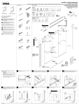
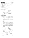
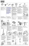
HAND SHOWERS
AND HAND SHOWER ACCESSORIES
BEFORE YOU BEGIN
HOW TO USE THESE INSTRUCTIONS
Please read these instructions carefully to familiarize
yourself with the required tools, materials, and installation
sequences. Follow the sections that pertain to your
particular installation. This will aid you in avoiding the
unnecessary expense associated with improper
installation. In addition to proper installation, read all
operating and safety instructions.
ORDERING INFORMATION
Three-way hand shower* . . . . . . . . . . . . . . . . . . . . K-9502
Regular hand shower* . . . . . . . . . . . . . . . . . . . . . . K-9503
Brush attachment kit . . . . . . . . . . . . . . . . . . . . . . . K-9504
Wall supply elbow . . . . . . . . . . . . . . . . . . . . . . . . . . K-9513
Shower hose . . . . . . . . . . . . . . . . . . . . . . . . . . . . . . K-9514
Adjustable bracket . . . . . . . . . . . . . . . . . . . . . . . . . K-9515
Shower bar . . . . . . . . . . . . . . . . . . . . . . . . . . . . . . . K-9516
Soap dish . . . . . . . . . . . . . . . . . . . . . . . . . . . . . . . . . K-9517
Three-way hand shower - Revival* . . . . . . . . . . K-16126
All information in these instructions is based on the latest
product information available at the time of publication.
Kohler Co. reserves the right to make changes in product
characteristics, packaging, or availability at any time
without notice.
TOOLS AND MATERIALS REQUIRED
1/2” shower ell
Adjustable wrench
Strap wrench
Thread sealant
Clear silicone caulk
3/8” hex wrench
3/16”, 1/4” and 3/8” masonry drill bits
* A check valve installed in the hand shower provides
anti-siphonage/back pressure protection. Consult local
plumbing code for vacuum breaker requirements. If
required, Kohler offers the K-13056 or K-9660 vacuum
breaker.
112774-2-DA (A)
1999 Kohler Co.
INSTALLATION
For rough-in dimensions, see Fig. #1.
6”
12-1/2” MAX.
2-7/8”
59” OVERALL
LENGTH
16”
K-9516
59”
OVERALL
LENGTH
2-7/8”
1-5/8”
24”
1-3/4”
K-9502
K-16126
K-9504
3-1/16”
Fig. #1
3/4”
3-3/4”
K-9517
2-7/16” D.
1-5/8” D.
K-9514
K-9515
6-1/4”
1/2” I.P.S.
1-3/8” G1/2-14
K-9513
Fig. #1
FOR K-9513 WALL ELBOW
Rough-in 1/2” I.P.S. nipple to extend 9/16” from finished
wall. Slide O-ring and escutcheon onto elbow. Hint: Use
water to wet O-ring surface for easier assembly. Thread
wall elbow onto nipple. Tighten using a clean strap wrench
or a sturdy screwdriver inserted into the outlet.
1/2” I.P.S. Nipple
Wall Elbow
9/16”
NOTE: Adapter and escutcheon may be removed to
provide clearance for a strap wrench.
Finished Wall
Use a 3/8” hex wrench to remove adapter. Place a clear
silicone caulk or adhesive behind escutcheon. Push
escutcheon against wall.
Fig. #2
For installations not using wall elbow, provide a 1/2” I.P.S.
male outlet (either a plated nipple or shower arm) for
K-9514 shower hose.
112774-2-DA (A)
2
Kohler Co., Kohler, WI
FOR K-9515 ADJUSTABLE BRACKET
Drill a 3/16” hole through tile only for mounting directly to
stud. If stud cannot be located, drill a 3/8” hole to fasten
with wall anchor provided. Mark location of anti-rotation
pin and drill a 1/4” dia. hole 9/16” center-to-center from
anchor hole to pin hole.
1/4” D. Pin Hole
9/16”
NOTE: This accessory should not be installed in the
critical support area as defined in ASTM F446 (24”-48”
from floor).
3/8” D. Anchor Hole
Finished Wall
Fig. #3
FOR TOGGLE ANCHORS
Anchor
For installing the toggle anchors: Press and hold the
anchor legs together and insert into hole. If anchor is
inserted into a stud, the anchor legs will stay together. If
anchor is inserted into the space between studs; insert a
nail into anchor hole to open legs behind wall. Carefully
tap anchor until flush with finished surface.
Finished
Wall
Nail
Fig. #4
Unthread bracket from assembly. Align bracket onto
holes and tighten screw into wall anchor. Place friction
washer into bracket and begin threading arm onto
bracket. Hand-tighten.
Wall Anchor
Bracket
Screw
Friction Washer
Ball Joint
Arm
Fig. #5
FOR K-9517 SOAP DISH
End Bracket
Remove end bracket and grommet from desired end of
K-9516 shower bar. Loosen adjustment nut on soap dish.
Align keyway between collet and dish. Slide soap dish
onto shower bar so soap dish will face up when installed.
Recommended installation of soap dish is below hand
shower holder.
Grommet
Collet
Soap Dish
Adjustment Nut
Shower Bar
Fig. #6
Kohler Co., Kohler, WI
3
112774-2-DA (A)
Top Bracket
FOR K-9516 SHOWER BAR
Remove loose end bracket to attach soap dish (see
K-9517). Align bushing so alignment tab aligns with back
of shower bar bracket slot. Firmly press bracket onto
shower bar. Carefully tap bracket onto bar to ensure bar
is fully inserted into bracket. This is essential to provide
adequate pull strength of completed shower bar
assembly.
End Cap
Bushing
Shower Bar
Fig. #7
Shower bar must be mounted to stud framing support at
both top and bottom. Wall anchors will not provide
sufficient support. Drill a 3/16” hole through tile only at
desired location for bottom of shower bar. Place washer
over supplied screw and begin threading screw through
bottom shower bar bracket and into stud. Do not tighten
screw yet. Slide shower bar down so screw contacts top
of slot.
3/16” D.
Hole
Shower Bar Bottom
Washer
Screw
Finished
Wall
Fig. #8
Align shower bar so bar will be vertical and mark location
of hole for top bracket. Swivel shower bar out of the way
and drill hole for top bracket in center of slot. Secure
shower bar top bracket with washer and screw. Check
alignment. Securely tighten both bracket screws.
Top Bracket
Shower Bar
Hand Shower
Holder
Soap Dish
(Recommended Location)
Bottom Bracket
Fig. #9
112774-2-DA (A)
4
Kohler Co., Kohler, WI
Slide end caps over brackets and snap into place.
Top Bracket
End Cap
To adjust location of hand shower holder, rotate knob
opposite hand shower receptacle.
Shower Bar
Fig. #10
FOR K-9504 BRUSH ATTACHMENT KIT
3/16” D. Hole
NOTE: Kit consists of fixed wall bracket, handle
extension, and brush attachment.
1-1/4”
Wall Bracket
For fixed wall bracket, bracket must be attached to stud
framing. Drill a 3/16” hole through tile only at desired
location and a 1/4” hole for anti-rotation pin at 1-1/4” from
center-to-center. Secure wall bracket to wall with screw.
Finished
Wall
1/4” D.
Pin Hole
Fig. #11
NOTE: This accessory should not be installed in the
critical support area as defined in ASTM F446 (24”-48”
from floor).
Insert screen/washer into female end of handle extension
(supplied in kit). Thread on hand shower (not supplied in
kit). Insert gasket into shower hose. Hand tighten hose to
handle extension.
Hand Shower
Handle Extension
Screen/Washer
Shower
Hose
Gasket
Fig. #12
Slide brush attachment over end of hand shower until
firmly seated.
Hand Shower
Brush Attachment
Fig. #13
Gasket
FOR K-9514 SHOWER HOSE
Place gasket into the wrench-flats end of the hose. Firmly
thread hose to 1/2” I.P.S. shower outlet. Place
screen/washer in other end of hose before threading to
hand shower or handle extension. If there are two
gaskets, only one will be used in applications without a
handle extension.
Kohler Co., Kohler, WI
Screen/
Washer
Hose
Fig. #14
5
112774-2-DA (A)
Outer
Ring
FOR K-9502, K-9503,
OR K-16126 HAND SHOWER
Flush lines with hand showers removed. Insert rubber
washer with screen into hand shower. Firmly thread hand
shower or handle extension to shower hose.
Check hand shower head for smooth operation.
For three-way hand shower, grasp the outer ring of the
showerhead and gently rotate clockwise or
counterclockwise. There are two small detents within the
outer ring to provide the three operating positions.
Hand Shower
Fig. #15
For one-way adjustable hand shower, grasp the outer ring
of the showerhead and rotate to change the spray pattern.
NOTE: If winterizing hand shower, blow water out of
showerhead with air.
SERVICE PROCEDURES
If cause of problem is unknown, see troubleshooting chart
first. Then refer to procedure by component assembly
subheading.
Use an open-end or adjustable wrench to remove hand
shower from hose. Blow water out of hand shower head
with air.
For any flow/performance problem, the first item to check
is the inlet screen and flow control located in the end of the
handle.
INLET SCREEN/WASHER AND FLOW
CONTROL
Hand
Shower
Inlet
At inlet end of hand shower, use thin-bladed screwdriver
to gently pry up edge of the inlet screen/washer.
Orifice
Holes
Screen/
Washer
Flow Control
Remove and clean screen/washer. While screen/washer
is removed, visually inspect the three orifice holes in the
flow control. If holes in flow control require cleaning, use
a toothpick or similar thin, pointed tool to clean the three
holes.
Fig. #16
NOTE: The flow control is press fit into place and cannot
be removed.
Hand Shower
AERATOR HOUSING
(THREE-WAY MODELS ONLY)
Using the special tool provided, insert prongs into aerator
housing holes on face of showerhead. Turn tool
counterclockwise to remove aerator housing.
Showerhead Tool
Fig. #17
112774-2-DA (A)
6
Kohler Co., Kohler, WI
Remove rubber gasket and aerator plate. Turn housing
over, letting aerator fall out. Clean both sides of aerator.
Aerator Housing
Replace aerator into aerator housing, aligning notch in
aerator with keyway in aerator housing.
Aerator
Aerator Plate
Replace aerator plate with small diameter ring facing up.
Replace gasket. Unless proceeding to front housing
assembly service, replace assembly into showerhead. Do
not overtighten.
Gasket
Fig. #18
FRONT HOUSING ASSEMBLY
Align large hex end of showerhead tool with flats of hex
nut on showerhead assembly. Turn tool counterclockwise
to remove hex nut from showerhead.
Thrust
Washer
Using thin-bladed screwdriver, remove plastic thrust
washer from front housing assembly.
Using thin-bladed screwdriver, remove diffuser from front
housing assembly.
Diffuser
Clean diffuser by flexing to break loose mineral deposits.
Place diffuser, with small end of groove facing out, into
front housing assembly. Reinstall thrust washer and hex
nut. Reinstall aerator assembly. Reinstall hand shower on
shower hose.
Fig. #19
Test showerhead for proper and smooth operation.
TROUBLESHOOTING CHART
SYMPTOM
Low flow or poor
performance.
PROBABLE CAUSE
CORRECTIVE ACTION
Clogged inlet screen.
Inspect and clean or replace screen in handle
assembly.
Clogged flow control.
Inspect and clean orifice holes in flow control.
Poor spray pattern on
regular spray.
Clogged spray ring.
Disassemble spray ring/thrust washer from front
housing assembly; inspect and clean spray
ring/thrust washer.
Soft spray not aerating
(three-way models only).
Clogged screens in
aerator.
Disassemble screens from aerator housing and
clean or replace screens.
Pulsating spray not
pulsing (three-way
models only).
Worn parts or debris in
assembly.
Replace front housing assembly. (Service
technicians: consult service manual.)
Leaks between hose and
handspray or out top of
handle of handspray.
Poor seal between hose
and handspray.
Check to assure screen washer is in place.
Kohler Co., Kohler, WI
7
112774-2-DA (A)
112774-2-DA (A)
8
Kohler Co., Kohler, WI