1
GB
BU 0500
SK 500E
Users Manual for Frequency Inverters
SK 500E – Users Manual for Frequency Inverters
Pos : 2 /Anl eitung en/El ektr oni k/FU und Starter/0. Pr olog/0.1 Sicherheits- und Anwendungshi nweise für Antriebss tromrichter @ 0\mod_1325778640201_388.doc x @ 5201 @ @ 1
NORD frequency inverters
Safety and operating instructions for drive power converters
(as per: Low Voltage Directive 2006/95/EEC )
1. General
During operation, drive power converters may, depending on their
protection class, have live, bare, moving or rotating parts or hot
surfaces.
Unauthorised removal of covers, improper use, incorrect installation or
operation causes a risk of serious personal injury or material damage.
Further information can be found in this documentation.
All transportation, installation and initialisation and maintenance work
must be carried out by qualified personnel (comply with IEC 364,
CENELEC HD 384, DIN VDE 0100, IEC 664 and DIN VDE 0110, and
national accident prevention regulations).
For the purposes of these basic safety instructions, qualified personnel
are persons who are familiar with the assembly, installation,
commissioning and operation of this product and who have the relevant
qualifications for their work.
2. Proper use in Europe
Drive power converters are components intended for installation in
electrical systems or machines.
When installed in machines, the drive power converter cannot be
commissioned (i.e. commencement of the proper use) until it has been
ensured that the machine meets the provisions of the EC Directive
2006/42/EEC (machine directive); EN 60204 must also be complied
with.
Commissioning (i.e. implementation of the proper use) is only permitted
when the EMC directive (2004/108/EEC) is complied with.
Drive power converters with the CE mark meet the requirements of the
Low Voltage Directive 2006/95/EEC. The harmonized standards stated
in the Declaration of Conformity are used for the drive power converters.
Technical data and information for connection conditions can be found
on the rating plate and in the documentation, and must be complied
with.
The drive power converters may only be used for the safety functions
which are described and for which they have been explicitly approved.
3. Transport, storage
Information regarding transport, storage and correct handling must be
complied with.
4. Installation
The installation and cooling of the equipment must be implemented
according to the regulations in the corresponding documentation.
The drive power converter must be protected against
impermissible loads. Especially during transport and handling,
components must not be deformed and/or insulation distances
must not be changed. Touching of electronic components and
contacts must be avoided.
Drive power converters have electrostatically sensitive
components, which can be easily damaged by incorrect
handling. Electrical components must not be mechanically
damaged or destroyed (this may cause a health hazard!).
5. Electrical connections
When working on live drive power converters, the applicable
national accident prevention regulations must be complied with
(e.g. VBG A3, formerly VBG 4).
The electrical installation must be implemented according to the
applicable regulations (e.g. cable cross-section, fuses, ground
lead connections). Further instructions can be found in the
documentation.
Information about EMC-compliant installation – such as
shielding, earthing, location of filters and installation of cables
can be found in the drive power converter documentation.
These instructions must be complied with even with CE marked
drive power converters. Compliance with the limiting values
specified in the EMC regulations is the responsibility of the
manufacturer of the system or machine.
6. Operation
Where necessary, systems where drive power converters are
installed must be equipped with additional monitoring and
protective equipment according to the applicable safety
requirements, e.g. legislation concerning technical equipment,
accident prevention regulations, etc.
The parameterisation and configuration of the drive power
converter must be selected so that no hazards can occur.
All covers must be kept closed during operation.
7. Maintenance and repairs
After the drive power converter is disconnected from the power
supply, live equipment components and power connections
should not be touched immediately, because of possible
charged capacitors. Observe the relevant information signs
located on the drive power converter.
Further information can be found in this documentation.
These safety instructions must be kept in a safe place!
Pos : 3 /Anl eitung en/El ektr oni k/FU und Starter/0. Pr olog/0.2 Bes ti mmungsgemäß e Verwendung der Freq uenz umrichter [BU 0500] @ 0\mod_1325778851914_388.doc x @ 5224 @ @ 1
2
BU 0500 GB-1013
Intended use of the frequency inverter
Intended use of the frequency inverter
Compliance with the operating instructions is necessary for fault-free operation
and the acceptance of any warranty claims. These operating instructions must
be read before working with the device!
These operating instructions contain important information about servicing.
They must therefore be kept close to the device.
SK 500E series frequency inverters are devices for industrial an commercial
systems used for the operation of three-phase asynchronous motors with squirrelcage rotors and Permanent Magnet Synchronous Motors – PMSM (SK 54xE and
above) These motors must be suitable for operation with frequency inverters, other
loads must not be connected to the devices.
SK 5xxE frequency inverters are devices for stationary installation in control
cabinets. All details regarding technical data and permissible conditions at the
installation site must be complied with.
Commissioning (commencement of the intended use) is not permitted until it has
been ensured that the machine complies with the EMC Directive 2004/108/EEC
and that the conformity of the end product meets the Machinery Directive
2006/42/EEC (observe EN 60204).
ã Getriebebau NORD GmbH & Co. KG, 2013
Pos : 4 /Anl eitung en/El ektr oni k/FU und Starter/0. Pr olog/0.3 D okumentation - Versionsliste [BU 0500] @ 0\mod_1325778935605_388.doc x @ 5247 @ @ 1
BU 0500 GB-1013
3
SK 500E – Users Manual for Frequency Inverters
Documentation
Name:
BU 0500
Part No.:
607 50 01
Series:
SK 500E
FI series:
SK 500E, SK 505E, SK 510E, SK 511E,
SK 515E, SK 520E, SK 530E, SK 535E,
FI types:
SK 5xxE-250-112-O ... SK 5xxE-750-112-O
(0.25 – 0.75kW, 1~ 115V, output 3~ 230V)
SK 5xxE-250-323-A ... SK 5xxE-221-323-A
0.25 - 2.2kW, 1/3~ 230V, output 3~ 230V)
SK 5xxE-301-323-A ... SK 5xxE-182-323-A
(3.0 – 18.0kW, 3~ 230V, output 3~ 230V)
SK 5xxE-550-340-A ... SK 5xxE-902-340-A
(0.55 – 90.0kW, 3~ 400V, output 3~ 400V)
Version list
Name of previous issues
Software
Version
Remarks
BU 0500 DE, March 2005
V 1.1 R1
First issue based on BU 0750 DE
Further revisions:
May, June, August, December 2005, May, October 2006, May, August 2007, February, May 2008
(For an overview of the amendments to the above editions: please refer to the April 2009 version (Part No.:
6075001/1409))
Further revisions:
April 2009, November 2010, February, April 2011
(For an overview of the amendments to the above editions: please refer to the April 2011 version (Part No.:
6075001/1411))
BU 0500 DE, September 2011
V 2.0 R0
please refer to the September 2011 edition (Part No.:
6075001/3811)
V 2.0 R5
These include:
Part No. 607 5001 / 3811
BU 0500 DE, March 2013
Part No. 607 5001 / 1013
· Addition of size 8 and size 9 (45 kW ... 90 kW)
· Modification of the UL data, mains fuses, e.g. RK types
· Revision of section structure
· Removal of the parameter summary list
· Correction of the snap-on rail mounting kit SK DRK1-...
· Description of control boxes SK TU3-CTR and
SK TU3-PAR removed (see BU0040)
· Addition of E004 in the description of errors
· Removal of SK54xE devices and transfer to a new
document (BU0505)
Table 1: Version list
Pos : 8 /Anl eitung en/El ektr oni k/FU und Starter/0. Pr olog/0.4 H erausgeber @ 0\mod_1325779078002_388.doc x @ 5270 @ @ 1
Publisher
Getriebebau NORD GmbH & Co. KG
Rudolf-Diesel-Str. 1 · D-22941 Bargteheide · http://www.nord.com/
Tel.: +49 (0) 45 32 / 289-0 · Fax +49 (0) 45 32 / 289-2555
=== Ende der Liste für T extmar ke Copyright ===
4
BU 0500 GB-1013
Publisher
BU 0500 GB-1013
5
SK 500E – Users Manual for Frequency Inverters
Pos : 10 /Anl eitungen/Steuer module/Inhalts verzeic hnis @ 0\mod_1317978518480_388.doc x @ 4078 @ @ 1
Table of Contents
=== Ende der Liste für T extmar ke Inhalts verz eichnis ===
1.
General ....................................................................................................................................................... 11
1.1
Overview .......................................................................................................................................... 11
1.2
Delivery ............................................................................................................................................ 13
1.3
Scope of delivery.............................................................................................................................. 13
1.4
Safety and installation information ................................................................................................... 13
1.4.1
Explanation of labels used.................................................................................................. 14
1.4.2
List of Safety and installation information ........................................................................... 14
1.5
Certifications .................................................................................................................................... 16
1.5.1
European EMC Directive .................................................................................................... 16
1.5.2
UL and cUL approvals for frequency inverters (CSA) ......................................................... 16
1.5.3
C-Tick labelling - No. N 23134 ............................................................................................ 19
1.5.4
RoHS compliant.................................................................................................................. 19
1.6
Type codes / Device versions .......................................................................................................... 19
2.
Assembly and installation ........................................................................................................................ 22
2.1
SK 5xxE, standard version ............................................................................................................... 23
2.2
SK 5xxE…-CP in ColdPlate version ................................................................................................. 24
2.3
External heat sink kit ........................................................................................................................ 25
2.4
Snap-on mounting rail kit SK DRK1-… ............................................................................................ 27
2.5
EMC Kit ............................................................................................................................................ 28
2.6
Brake resistor (BR)........................................................................................................................... 29
2.6.1
Electrical data, brake resistor ............................................................................................. 30
2.6.2
Dimensions of bottom-mounted BR SK BR4 ...................................................................... 31
2.6.3
Dimensions, brake resistor chassis SK BR2 ...................................................................... 33
2.7
Mains choke SK CI1......................................................................................................................... 34
2.8
Output choke SK CO1...................................................................................................................... 36
2.9
Line filter .......................................................................................................................................... 37
2.10 Electrical connections ...................................................................................................................... 40
2.10.1 Wiring guidelines ................................................................................................................ 41
2.10.2 Adaptation to IT networks ................................................................................................... 42
2.10.3 DC-coupling ........................................................................................................................ 44
2.10.4 Electrical connections, power unit ...................................................................................... 47
2.10.5 Electrical connections, control unit ..................................................................................... 49
2.11 Colour and contact assignments for encoders ................................................................................. 59
2.12 RJ45 WAGO- Connection module ................................................................................................... 60
2.13 Setpoint card ± 10V.......................................................................................................................... 61
3.
Displays and control ................................................................................................................................. 62
3.1
Modular assemblies SK 5xxE .......................................................................................................... 62
3.2
Overview of technology units ........................................................................................................... 63
3.3
SimpleBox, SK CSX-0 ...................................................................................................................... 65
4.
Commissioning ......................................................................................................................................... 68
4.1
Factory settings ................................................................................................................................ 68
4.2
Minimal configuration of control connections ................................................................................... 69
4.3
KTY84-130 connection (above software version 1.7)....................................................................... 70
4.4
Frequency addition and subtraction via operating boxes ................................................................. 71
5.
Parameters ................................................................................................................................................. 72
6.
Operating status messages ................................................................................................................... 140
6.1
Display of messages ...................................................................................................................... 140
6.2
Messages....................................................................................................................................... 141
7.
Technical data ......................................................................................................................................... 149
7.1
General Data SK 500E................................................................................................................... 149
7.2
Electrical data ................................................................................................................................ 150
7.2.1
Electrical data 115V.......................................................................................................... 150
6
BU 0500 GB-1013
Table of Contents
7.3
7.2.2
Electrical data 230V.......................................................................................................... 151
7.2.3
Electrical data 400V.......................................................................................................... 153
General conditions for ColdPlate technology ................................................................................. 156
8.
Additional information ............................................................................................................................ 158
8.1
Setpoint processing........................................................................................................................ 158
8.2
Process controller .......................................................................................................................... 160
8.2.1
Process controller application example ............................................................................ 160
8.2.2
Process controller parameter settings .............................................................................. 161
8.3
Electromagnetic Compatibility (abbreviation: EMC) ...................................................................... 162
8.4
EMC limit value classes ................................................................................................................. 162
8.5
Reduced output power ................................................................................................................... 164
8.5.1
Increased heat dissipation due to pulse frequency ........................................................... 164
8.5.2
Reduced overcurrent due to time ..................................................................................... 164
8.5.3
Reduced overcurrent due to output frequency.................................................................. 165
8.5.4
Reduced output current due to mains voltage .................................................................. 167
8.5.5
Reduced output current due to the heat sink temperature................................................ 167
8.6
Operation with FI circuit breakers................................................................................................... 167
8.7
Energy Efficiency ........................................................................................................................... 168
8.8
Standardisation of setpoint / target values ..................................................................................... 169
8.9
Definition of setpoint and actual value processing (frequencies) ................................................... 170
9.
Maintenance and servicing information ................................................................................................ 171
9.1
Maintenance Instructions ............................................................................................................... 171
9.2
Repair information .......................................................................................................................... 171
9.2.1
Repairs ............................................................................................................................. 172
9.2.2
Internet information........................................................................................................... 172
9.3
Abbreviations ................................................................................................................................. 173
BU 0500 GB-1013
7
SK 500E – Users Manual for Frequency Inverters
8
BU 0500 GB-1013
List of illustrations
Pos : 12 /Anl eitungen/Steuer module/Abbil dungs verz eic hnis @ 0\mod_1317978515699_388.doc x @ 3917 @ @ 1
List of illustrations
=== Ende der Liste für T extmar ke Abbildungs verzeic hnis ===
Fig. 1 SK 5xxE and accessories ............................................................................................................................ 20
Fig. 2 Frequency inverter type plate (example) ..................................................................................................... 21
Fig. 3 Mounting distances for SK 5xxE .................................................................................................................. 22
Fig. 4 EMC Kit SK EMC2-x .................................................................................................................................. 28
Fig. 5: Top: bottom-mounted brake resistor SK BR4- Bottom: chassis brake resistor SK BR2-... ......................... 29
Fig. 6 Diagram of a DC-coupling ........................................................................................................................... 45
Fig. 7 Diagram of a DC coupling with an input/feedback unit ................................................................................ 46
Fig. 8: Dimensions of setpoint card± 10V .............................................................................................................. 61
Fig. 9: Modular assemblies SK 5xxE ..................................................................................................................... 62
Fig. 10 SimpleBox SK CSX-0 ................................................................................................................................ 65
Fig. 11 Top side of FI with RJ12 / RJ45 connection ............................................................................................. 65
Fig. 12: SimpleBox, SK CSX-0 menu structure ..................................................................................................... 67
Fig. 13 Motor type plate ......................................................................................................................................... 68
Fig. 14: Setpoint processing ................................................................................................................................ 159
Fig. 15: Process controller flow diagram .............................................................................................................. 160
Fig. 16: Heat losses due to pulse frequency ........................................................................................................ 164
Fig. 17: Output current due to mains voltage....................................................................................................... 167
Fig. 18 Energy efficiency due to automatic flux optimisation ............................................................................... 168
BU 0500 GB-1013
9
SK 500E – Users Manual for Frequency Inverters
Pos : 14 /Anl eitungen/Steuer module/Tabell enverz eichnis @ 0\mod_1317978519199_388.doc x @ 4124 @ @ 1
List of tables
=== Ende der Liste für T extmar ke Tabellenverz eic hnis ===
Table 1: Version list ................................................................................................................................................. 4
Table 2: Overview of SK 500E performance grading features ............................................................................... 12
Table 3: Overview of differing hardware features .................................................................................................. 12
Table 4: EMC Kit SK EMC2-x .............................................................................................................................. 28
Table 5: Electrical data for brake resistor SK BR2-… and SK BR4-… .................................................................. 30
Table 6: Brake resistor temperature switch data ................................................................................................... 31
Table 7: Dimensions of bottom-mounted brake resistor SK BR4-... ...................................................................... 31
Table 8: Dimensions of chassis brake resistor SK BR2-... .................................................................................... 33
Table 9: Mains choke data for SK CI1-..., 1~ 240 V .............................................................................................. 34
Table 10: Mains choke data for SK CI1-..., 3~ 240 V ............................................................................................ 34
Table 11: Mains choke data for SK CI1-..., 3~ 480 V ............................................................................................ 35
Table 12: Output choke data for SK CO1-..., 3~ 240 V.......................................................................................... 36
Table 13: Output choke data for SK CO1-..., 3~ 480 V.......................................................................................... 37
Table 14: Mains filter NHD-... ................................................................................................................................ 37
Table 15: Mains filter LF2-... .................................................................................................................................. 38
Table 16: Mains filter HLD-... ................................................................................................................................. 38
Table 17: Mains filter SK CIF-................................................................................................................................ 39
Table 18: Integrated mains filter ............................................................................................................................ 42
Table 19: Tools 47
Table 20: Connection data .................................................................................................................................... 47
Table 21: Colour and contact assignments for NORD TTL incremental encoders ................................................ 60
Table 22: RJ45 WAGO connection module ........................................................................................................... 61
Table 23: Setpoint card ± 10V ............................................................................................................................... 61
Table 24: Overview of Technology Units and Control Boxes ................................................................................. 63
Table 25: Overview of Technology Units and Bus Systems .................................................................................. 63
Table 26: Overview of technology units, other optional modules ........................................................................... 64
Table 27: SimpleBox SK CSX-0, functions ............................................................................................................ 66
Table 28: Technical data, ColdPlate 115V / 230V devices .................................................................................. 156
Table 29: Technical data, ColdPlate 400V devices ............................................................................................. 157
Table 30: Overview of standards according to product standard EN 61800-3..................................................... 163
Table 31: Overcurrent relative to time ................................................................................................................. 165
Table 32: Overcurrent relative to pulse and output frequency ............................................................................. 166
Table 33: Scaling of setpoints and actual values (Selection)............................................................................... 169
Table 34: Processing of setpoints and actual values in the frequency inverter ................................................... 170
Pos : 16 /Anl eitungen/Elektroni k/FU und Starter/1. Allgemei nes/1. Allgemei nes [BU 0500] @ 0\mod_1325779554274_388.doc x @ 5293 @ 1 @ 1
10
BU 0500 GB-1013
1 General
1. General
The SK 500E series is based on the tried and tested NORD platform. These devices feature a
compact design with optimum control characteristics.
These frequency inverters are provided with sensorless vector current control system which in
combination with asynchronous three-phase motor types constantly ensures an optimised voltage-tofrequency ratio. For the drive unit, this means very high starting and overload torques with constant
speed.
As standard, the frequency inverters are equipped with a fixed heat sink, via which the power losses
are dissipated to the environment. Alternatively, for sizes 1 - 4 there is the ColdPlate version and for
sizes 1 and 2 there is also an external heat sink version.
This series of frequency inverters can be adapted to individual requirements by means of the modular
technology units.
Due to the wide range of setting options, these inverters can control all three-phase motors. The
power range is from 0.25 kW to 90.0 kW with integrated mains filter.
This manual is based on the device software as stated in the version list (see P707). If the frequency
inverter uses a different software version, this may cause differences. If necessary, the current manual
can be downloaded from the Internet (http://www.nord.com/).
There are additional descriptions for the optional functions "Functional Safety "(BU 0530) and the
"POSICON" positioning system (BU 0510) and the memory programmable "PLC" control units
(BU0550). Supplementary descriptions for the optional bus systems are also available
http://www.nord.com/).
Note
Accessories
The accessories mentioned in the manual (brake resistors, filters etc.) may also be subject to modifications.
Current details of these are included in separate data sheets, which are listed under www.nord.com under the
heading Documentation → Manuals → Frequency inverters → Data sheets. The data sheets available at the date
of publication of this manual are listed by name in the relevant sections (TI ...).
Pos : 17 /Anl eitungen/Elektroni k/FU und Starter/1. Allgemei nes/1.1 Ü ber blic k -1- [BU 0500] @ 0\mod_1325779961835_388.doc x @ 5316 @ 2 @ 1
1.1
Overview
Properties of the basic frequency inverter SK 500E:
•
•
•
•
•
•
•
•
•
•
High starting torque and precise motor speed control setting with sensorless current vector
control
Can be mounted next to each other without additional spacing
Permissible ambient temperature range 0 to 50°C (please refer to the technical data)
Integrated EMC mains filter for limit curve A1 (and B1 for size 1 - 4 devices) as per EN55011
(not for 115V devices)
Automatic measurement of the stator resistance or determination of the precise motor data
Programmable direct current braking
Integrated brake chopper for 4 quadrant operation (optional brake resistors)
Four separate online switchable parameter sets
RS232/485 interface via RJ12 plug connector
USS-integrated (see BU 0050)
BU 0500 GB-1013
11
SK 500E – Users Manual for Frequency Inverters
Feature
SK …
50xE
51xE
Operating manual
511E
520E
53xE
BU 0505
Additional
options
x
x
BU 0530
x
x
x
BU 0060
x
x
x
x
x
x
x
x
x
x
x
BU 0510
BU 0510
BU 0550
x
BU 0510
BU 0500
Safe pulse block (STO / SS1)*
2 x CANbus/CANopen interfaces via RJ45
plug
RS485 interface additionally via terminals
Speed feedback via incremental encoder
input
Integrated “POSICON” positioning control
CANopen absolute encoder evaluation
PLC / SPS – functionality
Universal
encoder
interface
(SSI, BISS, Hiperface, EnDat and
SIN/COS)
Operation
of
PMSM
(Permanent Magnet Synchronous Motors)
Modbus RTU
x
x
x
54xE
x
Number of digital inputs / outputs**
5/0
5/0
5/0
7/2
7/2
Additional potential-isolated PTC input***
Number of analog inputs / outputs
Number of relay messages
2/1
2
2/1
2
2/1
2
2/1
2
2/1
2
x
5/36/2
7/1
x
2/1
2
BU 0050
* not with 115 V devices
** SK 54xE: 2 I/Os can be variably parameterised as inputs or outputs
*** alternative "thermistor" function on digital input 5 possible (above size 5 an additional thermistor input is available as
standard)
Table 2: Overview of SK 500E performance grading features
Pos : 18 /Anl eitungen/Elektroni k/FU und Starter/1. Allgemei nes/1.1 Ü ber blic k -2- Abweic hende H ardwareeigenschaften [BU 0500] @ 1\mod_1340695009508_388.doc x @ 28170 @ @ 1
Differing hardware features
Version
Description
SK 5xxE-…-CP
compared with SK 5xxE
·
ColdPlate or external heat sink
SK 5x5E
compared with SK 5x0E
·
External 24V supply voltage. Communication with the frequency inverter is
possible even without a power connection
For size 5 and above in
comparison with sizes 1 –
4 (> 4 kW, 230V or
> 11 kW, 400V)
·
Additional, separately mounted PTC input (potential isolated)
·
External 24V supply voltage with automatic switchover to the internal 24V low
voltage generator on failure of the external control voltage.
·
Processing of both bipolar and analog signals
·
2 x CANbus/CANopen interfaces via RJ45 plug as standard
Table 3: Overview of differing hardware features
Pos : 19 /Anl eitungen/Elektroni k/FU und Starter/1. Allgemei nes/1.2 Lieferung @ 0\mod_1325780242208_388.doc x @ 5339 @ 2 @ 1
12
BU 0500 GB-1013
1 General
1.2
Delivery
Check the equipment immediately after delivery/unpacking for transport damage such as deformation
or loose parts.
If there is any damage, contact the carrier immediately and carry out a thorough assessment.
Important! This also applies even if the packaging is undamaged.
Pos : 20 /Anl eitungen/Elektroni k/FU und Starter/1. Allgemei nes/1.3 Lieferumfang [BU 0500] @ 0\mod_1325780384629_388.doc x @ 5362 @ 2 @ 1
1.3
Scope of delivery
Standard version:
Available
accessories:
IP20
Integrated brake chopper
Integrated EMC mains filter for limit curve A1 as per EN55011
devices)
Blanking cover for technology unit slot
Screening terminal for control terminals
Covering for the control terminals
Size 1 to Size 7: Accessory bag with wall mounting brackets
Size 8 and above: miscellaneous electrical connection material
Operating instructions on CD
Braking resistor, mains filter, mains chokes, output chokes, link circuit choke
(size 8 and above), EMC kit (SK EMV ...), electronic brake rectifier SK EBGR1), IO extension for SK 54xE (SK EBIOE-2), interface converter RS232 ®
RS485 (supplementary description BU 0010), NORD CON PC
parameterisation software > www.nord.com <, ePlan macros for creating
electrical circuit diagrams > www.nord.com <
Technology units for clipping onto the frequency inverter for control and
parameterisation or as communication interface for various bus systems.
Pos : 21 /Anl eitungen/Elektroni k/FU und Starter/1. Allgemei nes/1.4 Sicherheits- und Installati onshi nweis e @ 0\mod_1325780428207_388.doc x @ 5385 @ 2 @ 1
1.4
Safety and installation information
NORD frequency inverters are equipment for use in industrial high voltage systems and are operated
at voltages that could lead to severe injuries or death if they are touched.
The frequency inverter and its accessories must only be used for the purpose which is intended by the
manufacturer. Unauthorised modifications and the use of spare parts and additional equipment which
has not been purchased from or recommended by the manufacturer of the frequency inverter may
cause fire, electric shock and injury.
All of the associated covers and protective devices must be used.
Installation and other work may only be carried out by qualified electricians with strict adherence to the
operating instructions. Therefore keep these Operating Instructions at hand, together with all
supplementary instructions for any options which are used, and give them to each user.
Local regulations for the installation of electrical equipment and accident prevention must be complied
with.
Pos : 22 /Anl eitungen/Elektroni k/FU und Starter/1. Allgemei nes/1.4.1 Erl äuter ung der verwendeten Kennz eic hnungen @ 1\mod_1341559156309_388.doc x @ 30301 @ 3 @ 1
BU 0500 GB-1013
13
SK 500E – Users Manual for Frequency Inverters
1.4.1
Explanation of labels used
DANGER
Indicates an immediate danger, which may result in death or serious injury.
WARNING
Indicates a possibly dangerous situation, which may result in death or
serious injury.
CAUTION
Indicates a possibly dangerous situation, which may result in slight or
minor injuries.
NOTICE
Note
Indicates a possibly harmful situation, which may cause damage to the
product or the environment.
Indicates hints for use and useful information.
Pos : 23 /Anl eitungen/Elektroni k/FU und Starter/1. Allgemei nes/1.4.2 Auflis tung der Sicherheits- und Installati onshi nweise @ 1\mod_1341560303401_388.doc x @ 30325 @ 3 @ 1
1.4.2
List of Safety and installation information
DANGER
Danger of electric shock
The frequency inverter operates with a dangerous voltage. Touching certain conducting components (connection
terminals, contact rails and supply cables as well as the PCBs) will cause electric shock with possibly fatal
consequences.
Even when the motor is at a standstill (e.g. caused by an electronic block, blocked drive or output terminal shortcircuit), the line connection terminals, motor terminals and braking resistor terminals, contact rails, PCBs and
supply cables may still conduct hazardous voltages. A motor standstill is not identical to electrical isolation from
the mains.
Only carry out installations and work if the device is disconnected from the voltage and wait at least 5
minutes after the mains have been switched off! (The equipment may continue to carry hazardous voltages for
up to 5 minutes after being switched off at the mains).
Follow the 5 Safety Rules (1. Switch off the power, 2. Secure against switching on, 3, Check for no voltage, 4.
Earth and short circuit, 5. Cover or fence off neighbouring live components).
DANGER
Danger of electric shock
Even if the drive unit has been disconnected from the mains, a connected motor may rotate and possible
generate a dangerous voltage. Touching electrically conducting components may then cause an electric shock
with possible fatal consequences.
Therefore prevent connected motors from rotating.
14
BU 0500 GB-1013
1 General
WARNING
Danger of electric shock
The voltage supply of the frequency inverter may directly or indirectly put it into operation, or touching electrically
conducting components may then cause an electric shock with possible fatal consequences.
Therefore, all poles of the voltage supply must be disconnected. For devices with a 3-phase supply,
L1 / L2 / L3 must be disconnected. For devices with a single phase supply, L1 / N must be disconnected. For
devices with a DC supply, –DC / +B must be disconnected. Also, the motor cables U / V / W must be
disconnected.
WARNING
Danger of electric shock
In case of a fault, insufficient earthing may cause an electric shock with possibly fatal consequences if the device
is touched.
Because of this, the frequency inverter is only intended for permanent connection and may not be operated
without effective earthing connections which comply with local regulations for large leakage currents (> 3.5mA).
EN 50178 / VDE 0160 stipulates the installation of a second earthing conductor or an earthing conductor with a
2
cross-section of at least 10mm .
WARNING
Danger of injury if motor starts
With certain setting conditions, the frequency inverter or the motor which is connected to it may start automatically
when the mains are switched on. The machinery which it drives (press / chain hoist / roller / fan etc.) may then
make an unexpected movement. This may cause various injuries, including to third parties.
Before switching on the mains, secure the danger area by warning and removing all persons from the danger
area.
CAUTION
Danger of burns
The heat sink and all other metal components can heat up to temperatures above 70°C.
Touching such components may cause local burns to the affected parts of the body (hands, fingers, etc.).
To prevent such injuries, allow sufficient time for cooling down before starting work - the surface temperature
should be checked with suitable measuring equipment. In addition, keep sufficient distance from adjacent
components during installation, or install protection against contact.
NOTICE
Damage to the frequency inverter
For single phase operation (115/230V) the mains impedance must be at least 100µH for each conductor. If this is
not the case, a mains choke must be installed.
Failure to comply with this may cause damage to the frequency inverter due to impermissible currents in the
components.
NOTICE
EMC - Interference
The frequency inverter is a product which is intended for use in an industrial environment and is subject to sales
restrictions according to IEC 61800-3. Use in a residential environment may require additional EMC measures.
For example, electromagnetic interference can be reduced by the use of an optional mains filter.
BU 0500 GB-1013
15
SK 500E – Users Manual for Frequency Inverters
NOTICE
Leakage and residual currents
Due to their principle of operation (e.g. due to integrated mains filters, mains units and capacitor banks),
frequency inverters generate leakage currents. For the correct operation of the frequency inverter on a currentsensitive RCD, the use of an all-current sensitive earth leakage circuit breaker (Type B) compliant with EN 50178
/ VDE 0160 is necessary.
Note
Operation on TN- / TT- / IT- networks
The frequency inverters are suitable for operation on TN or TT networks as well as for IT networks with the
configuration of the integrated mains filter.
Note
Maintenance
In normal use, frequency inverters are maintenance free.
The cooling surfaces must be regularly cleaned with compressed air if the ambient air is dusty.
In case of long-term shut-down or long-term storage, the capacitors must be re-formed (refer to "Technical Data").
Failure to do this will damage these components and will cause a considerable reduction of the service life including the immediate destruction of the frequency inverter.
Pos : 24 /Anl eitungen/Elektroni k/FU und Starter/1. Allgemei nes/1.5 Z ulas sungen @ 0\mod_1326111302308_388.doc x @ 6223 @ 2 @ 1
1.5
Certifications
Pos : 25 /Anl eitungen/Elektroni k/FU und Starter/1. Allgemei nes/1.5.1 Eur opäisc he EM V-Richtli nie @ 0\mod_1325780630565_388.doc x @ 5431 @ 3 @ 1
1.5.1
European EMC Directive
If the frequency inverter is installed according to the recommendations in this manual, it meets all
EMC directive requirements, as per the EMC product standard for motor-operated systems EN 618003.
Pos : 26 /Anl eitungen/Elektroni k/FU und Starter/1. Allgemei nes/1.5.2 Z ulass ungen Freq uenz umrichter U L und cUL [BU 0500] @ 0\mod_1325780690549_388.doc x @ 5454 @ 355 @ 1
1.5.2
UL and cUL approvals for frequency inverters (CSA)
All SK 500E frequency inverters include motor overload protection. Further technical details can be
found in Section 7.2.
NOTICE
"Integral solid state short circuit protection does not provide branch circuit protection. Branch circuit protection
must be provided in accordance with the National Electric Code and any additional local codes."
The integral short-circuit protection does not provide branch circuit protection. Branch circuit protection must be
provided in accordance with the manufacturer's instructions, the "National Electric Code" and all additional local
regulations.
Note
“Use 75°C Copper Conductors Only" - “Anschluss von Kupferkabel mit einer Isolationsfestigkeit von mind. 75°C“
(betrifft ausschließlich Anschlussleitungen (Netz- / Motorkabel aber nicht Steuerleitungen))
„These products are intended for use in a pollution degree 2 environment“ - „Das Produkt ist für den Betrieb in
Umgebungen mit Verschmutzungsgrad 2 geeignet“
"Maximum Surrounding Air Temperature 40°C" - “Maximale Umgebungstemperatur 40°C”
16
BU 0500 GB-1013
1 General
UL- Approval - File No. E171342
Frequency inverter
SK 5xxE-xxx-
Fuses
Size
1…4
5, 6
Circuit Breaker
Type
7
Circuit
Circuit
C,J,R,T
G, L
[V]
[A] rms
[V]
[A] rms
-112
X
X
X
300
100 000
480
10 000
-323
X
X
X
300
100 000
480
10 000
X
-
300
65 000
480
65 000
X
X
300
100 000
480
65 000
X
X
600
100 000
480
10 000
X
-
600
65 000
480
65 000
X
X
600
100 000
480
65 000
-323
X
-323
-340 (/ -350)
X
X
-340 (/ -350)
-340 (/ -350)
X
X
referring to the table above
bezugnehmend zur obigen Tabelle
“Suitable for use on a circuit capable of delivering
not more than 65 000 or 100 000 rms symmetrical
Amperes, and when protected by High-Interrupting
Capacity, Current Limiting Fuses”.
“Suitable for use on a circuit capable of delivering
not more than 10 000 or 65 000 rms symmetrical
Amperes, and when protected by a Circuit Breaker
(inverse time trip type) in accordance with UL 489”,
having an interrupting rating of not less than 10 000
or 65 000 rms symmetrical Amperes, 480 Volts
maximum.
Geeignet für den Einsatz am Netz mit einem max.
Kurzschlussstrom von 65 000 A oder 100 000 A
(symmetrisch), und bei Schutz über eine
strombegrenzende
Sicherung“
mit
hohem
Ausschaltvermögen.
Geeignet für den Einsatz am Netz mit einem max.
Kurzschlussstrom von 10 000 A oder 65 000 A
(symmetrisch),
und
bei
Schutz
über
Sicherungsautomaten nach UL Kategorie DIVQ
(thermischer und elektromagnetischer Auslöser)
gemäß
UL 489,
mit
einem
Mindestausschaltvermögen von 10 000 A oder 65 000 A,
480 V Maximum.
Die
Stromwerte
der
Sicherungen
und
Leistungsschalter sind im Kapitel 0 aufgeführt.
The current ratings of the fuses and circuit
breakers are stated in Section 0.
Devices of size 5 and above - Use of terminals X12 or X8
"Intended to be connected only to isolated
secondary sources rated 24Vdc. Fuse in
accordance with UL 248 rated max. 4 A must be
provided externally between the isolated source
and this device input".
BU 0500 GB-1013
Wenn diese Klemmen genutzt werden um externe
Spannungen (24V) einzuspeisen, so muss für
einen
UL konformen Anschluss folgendes
berücksichtigt werden:
"Darf nur mit isoliertem Steuer-spannungskreis
(24Vdc) verbunden werden. Eine Sicherung
zwischen isoliertem Steuerspannungskreis und
diesem Eingang muss gemäß UL 248 ausgeführt
sein, darf maximal 4 A betragen und muss extern
bereitgestellt werden.“
17
SK 500E – Users Manual for Frequency Inverters
Supplement for cUL
Compliance with the conditions described below fulfils the requirements for
cUL approval as per CSA.
Frequency Inverters size 1 - 7
Frequenzumrichter Baugröße 1 - 7
“Suitable for use on a circuit capable of delivering
not more than 5 000 rms symmetrical Amperes,
• 240 Volts maximum (SK 5xxE-xxx-323) or
• 500 Volts maximum (SK 5xxE-xxx-340 /
SK 5xxE-xxx-350)
and when protected by High-Interrupting Capacity,
Current Limiting Fuses as described above”.
Geeignet für den Einsatz am Netz mit einem max.
Kurzschlussstrom von 5 000 A (symmetrisch),
“Suitable for use on a circuit capable of delivering
not more than 5 000 rms symmetrical Amperes,
• 240 Volts maximum (SK 5xxE-xxx-323) or
• 500 Volts maximum (SK 5xxE-xxx-340 /
SK 5xxE-xxx-350)
and when protected by a Circuit Breaker (inverse
time trip type) in accordance with UL 489”, having
an interrupting rating of not less than 5 000 rms
symmetrical Amperes, 480 Volts maximum.
Geeignet für den Einsatz am Netz mit einem max.
Kurzschlussstrom von 5 000 A (symmetrisch),
The current ratings of the fuses and circuit
breakers are stated in Section 0.
Die
Stromwerte
der
Sicherungen
und
Leistungsschalter sind im Kapitel 0 aufgeführt.
• 240 Volt Maximum (SK 5xxE-xxx-323) oder
• 500 Volt Maximum (SK 5xxE-xxx-340 /
SK 5xxE-xxx-350)
und bei Schutz über eine strombegrenzende
Sicherung“ mit hohem Ausschaltvermögen wie
oben beschrieben.
• 240 Volt Maximum (SK 5xxE-xxx-323) oder
• 500 Volt Maximum (SK 5xxE-xxx-340 /
SK 5xxE-xxx-350)
und bei Schutz über Sicherungsautomaten nach
UL
Kategorie
DIVQ
(thermischer
und
elektromagnetischer Auslöser) gemäß UL 489, mit
einem Mindest-ausschaltvermögen von 5 000 A,
480 V Maximum.
Devices size 1 - 6
“cUL only in combination with SK CIF-340-30 or
SK CIF-340-60 for 380 - 500V models and
SK CIF-323-20 or SK CIF-323-40 for 3 phase
200 - 240V rated models”.
The recognized transient surge suppression filter
board has to be connected between supply and the
input of the drive according to the instruction
manual.
Note
cUL Konformität, nur in Kombination mit SK CIF340-30 oder SK CIF-340-60 für 380 - 500V Typen
und SK CIF-323-20 oder SK CIF-323-40 für
200 - 240V Typen.
Das entsprechende Spannungs-begrenzungsfilter
(SK CIF-xxx-xx) ist zwischen Einspeisung und
Frequenzumrichter
(eingangsseitig)
nach
Handbuchangaben anzuschließen.
SK CIF-xxx
The supplementary requirements as per the cUL listing are fulfilled by the use of an appropriate overvoltage filter
SK CIF-323-xx or. SK CIF-340-xx.
For devices larger than size 7 no SK CIF-3xx-xx overvoltage filter is required.
Note
1~115V devices: no cUL approval
For SK500E series frequency inverters, no suitable CSA filter can be provided for the voltage range 1~115V
(SK 5xxE-xxx-112). For these types, (SK 5xxE-xxx-112) there is therefore NO cUL approval.
Pos : 27 /Anl eitungen/Elektroni k/FU und Starter/1. Allgemei nes/1.5.3 C-Tic k-Kennz eic hnung - No. N 23134 [SK 5xxE] @ 0\mod_1325835937619_388.doc x @ 5480 @ 3 @ 1
18
BU 0500 GB-1013
1 General
1.5.3
C-Tick labelling - No. N 23134
Frequency inverters of the NORD product series SK 500E (except 115V
devices: SK5xxE-xxx-112-O) comply with all the relevant regulations in
Australia and New Zealand.
Pos : 28 /Anl eitungen/Elektroni k/FU und Starter/1. Allgemei nes/1.5.4 R oHS- konfor m @ 0\mod_1325836122418_388.doc x @ 5503 @ 3 @ 1
1.5.4
RoHS compliant
The frequency inverters and optional modules are designed to be RoHS
compliant according to Directive 2002/95/EU.
Pos : 29 /Anl eitungen/Elektroni k/FU und Starter/1. Allgemei nes/1.6 T ypensc hl üss el / Ger äteaus führung [SK5xxE] @ 0\mod_1325859433216_388.doc x @ 5526 @ 2 @ 1
1.6
Type codes / Device versions
SK 500E-250-323-A-CP
Versions: CP = “ColdPlate” or “External heat sink technology”
Radio interference filter class: O = without, A or B limit value
Mains voltage: x12 = 115V, x23 = 230V, x40 = 400V, x50 = 500V
Number of mains phases: 1 = single phase, 3 = 3-phase *
Digits before comma for power: 0 = 0.xx, 1 = 0x.x0, 2 = 0xx.0
Device nominal power (xx): 25 = 0.25kW, 37 = 0.37kW up to 90 = 90.0kW
Device series:
SK 500E / SK 505E / SK 510E / SK 511E / SK 515E /
SK 520E / SK 530E / SK 535E / SK 540E / SK 545E
*) designation - 3 - also includes combined devices
which are intended for single and three-phase operation (please refer to the technical data)
BU 0500 GB-1013
19
SK 500E – Users Manual for Frequency Inverters
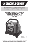
Optional Technology Unit
Wall mount bracket
including securing screw
additional control
terminals
Analog and digital
control terminals
SK 520E or higher
Encoder input
for SK 520E and higher
Optional EMC Kit:
Screening angle and clips
incl. fastening screws
Fig. 1 SK 5xxE and accessories
20
BU 0500 GB-1013
1 General
The type designation resulting from this type code can be obtained from the name plate which is
printed on the frequency inverter below the blank cover.
Fig. 2 Frequency inverter type plate (example)
Pos : 30 /Anl eitungen/Elektroni k/FU und Starter/2. M ontage und Ins tall ati on/2. Montage und Installati on [BU 0500] @ 0\mod_1325859552792_388.doc x @ 5572 @ 1 @ 1
BU 0500 GB-1013
21
SK 500E – Users Manual for Frequency Inverters
2. Assembly and installation
SK 500E frequency inverters are available in various sizes depending on the output. Attention must be
paid to a suitable position when installing.
The equipment requires sufficient ventilation to protect against overheating. For this the minimum
guideline distances from adjacent components above and below the frequency inverter, which could
obstruct the air flow apply. (above > 100 mm, below > 100 mm)
Distance from device: Mounting can be immediately next to each other. However, for the use of
brake resistances mounted below the frequency inverter (not possible with …-CP devices), the greater
width must be taken into consideration, particularly in combination with temperature switches on the
brake resistor!
Installation position: The installation position is normally vertical. It must be ensured that the cooling
ribs on the rear of the frequency inverter are covered with a flat surface to provide good convection.
Warm air must be vented above the device!
Fig. 3 Mounting distances for SK 5xxE
If several inverters are arranged above each other, it must be ensured that the upper air entry
temperature limit is not exceeded. (See also Section 0 ) If this is the case, it is recommended that an
"obstacle" (e.g. a cable duct) is mounted between the inverters so that the direct air flow (rising warm
air) is impeded.
Heat dissipation: If the frequency inverter is installed in a control cabinet, adequate ventilation must
be ensured. The heat dissipation in operation is approx. 5% (according to the size and equipment of
the device) of the rated power of the frequency inverter.
Pos : 31 /Anl eitungen/Elektroni k/FU und Starter/2. M ontage und Ins tall ati on/2.1 SK 5xxE in Standard- Aus führung [BU 0500] @ 0\mod_1325859863676_388.doc x @ 5618 @ 2 @ 1
22
BU 0500 GB-1013
2 Assembly and installation
2.1
SK 5xxE, standard version
Normally, the frequency inverter is mounted directly on the rear wall of a
control cabinet. For this, two, or for sizes 5 to 7, four matching wall mounting
brackets are supplied, which are to be inserted into the heat sink at the rear
of the device. For size 8 and above, the mounting device is integrated.
Alternatively, for sizes 1 ... 4 the wall mounting brackets can be inserted at
the side of the cooling element in order to minimise the necessary depth of
the control cabinet.
In general, care must be taken that the rear of the cooling element is covered
with a flat surface and that the device is mounted vertically. This enables
optimum convection, which ensures fault-free operation.
SK 5xxE-250- … to SK 5xxE-750- ...
SK 5xxE-111- … to SK 5xxE-221- …
SK 5xxE-301- … to SK 5xxE-401- …
SK 5xxE-551- 340… to SK 5xxE-751- 340…
SK 5xxE-551- 323… to SK 5xxE-751- 323…
SK 5xxE-112- 340… to SK 5xxE-152- 340…
SK 5xxE-112- 323…
SK 5xxE-182- 340… to SK 5xxE-222- 340…
SK 5xxE-152- 323… to SK 5xxE-182- 323…
SK 5xxE-302- 340… to SK 5xxE-372- 340…
SK 5xxE-452- 340… to SK 5xxE-552- 340…
SK 5xxE-752- 340… to SK 5xxE-902- 340…
Size
Frequency inverter type
Housing
dimensions
Size 1
Size 2
Size 3
Size 4
Size 5
Size 5
Size 6
Size 6
Size 7
Size 7
Size 8
Size 9
Wall-mounting
A
B
C
D
E
Æ
186
226
241
286
327
327
367
367
456
456
598
636
74*
74*
98
98
162
162
180
180
210
210
265
265
153
153
181
181
224
224
234
234
236
236
286
286
220
260
275
320
357
357
397
397
485
485
582
620
/
/
/
/
93
93
110
110
130
130
210
210
5.5
5.5
5.5
5.5
5.5
5.5
5.5
5.5
5.5
5.5
8.0
8.0
400V (…-340…) and 500V (…-350…) - FI:
identical dimensions and weights
*) for the use of brake resistors mounted below the device = 88 mm
Weight
Approx.
[kg]
1.4
1.8
2.7
3.1
8.0
8.0
10.3
10.3
15
16
20
25
All dimensions in [mm]
E
Pos : 32 /Anl eitungen/Elektroni k/FU und Starter/2. M ontage und Ins tall ati on/2.2 SK 5xxE…-CP i n C oldPlate- Aus führung [BU 0500] @ 0\mod_1325859970018_388.doc x @ 5641 @ 2 @ 1
BU 0500 GB-1013
23
SK 500E – Users Manual for Frequency Inverters
2.2
SK 5xxE…-CP in ColdPlate version
Instead of a cooling element/fan, ColdPlate versions of the frequency inverter have a flat metal plate
on the rear side which is mounted on an existing mounting plate (e.g. the rear wall of the control
cabinet) so as to provide thermal conduction. A liquid cooling medium (water, oil) may also be passed
through the mounting surface. In this way, not only is the waste heat from the frequency inverter
dissipated more effectively, but also the waste heat from the inverter is prevented from remaining
inside the control cabinet. In addition to the optimisation of the power reserved and the service life of
the inverter, this also causes less thermal load on the inside of the control cabinet.
A further advantage of the ColdPlate version is the reduced installation depth of the device and the
fact that in general, there is no need for a fan on the frequency inverter.
Size
Bottom-mounted brake resistors (SK BR4-…) cannot be mounted directly.
Frequency inverter type
Envelope dimensions
[mm]
Weight
Approx.
[kg]
ColdPlate dimensions [mm]
A/H
B
C
h1
h2
u/k
Thickness
SK 5xxE-250- …-CP
SK 5xxE-750- …-CP
1
182
95
119
91
-
5.5
10
1.3
SK 5xxE-111- …-CP
SK 5xxE-221- …-CP
2
222
95
119
111
-
5.5
10
1.6
SK 5xxE-301- …-CP
SK 5xxE-401- …-CP
3
237
120
119
75.33
75.33
5.5
10
1.9
SK 5xxE-551- 340…-CP
SK 5xxE-751- 340…-CP
4
282
120
119
90.33
90.33
5.5
10
2.3
B
k
u
B
B
C
k
u
H
Ø 4.5mm
A
H
h1
Ø 4.5mm
h1
h2
SK 5xxE-…CP
ColdPlate size 1 and size 2
ColdPlate size 3 and size4
Pos : 33 /Anl eitungen/Elektroni k/FU und Starter/2. M ontage und Ins tall ati on/2.3 D urc hstec k-Ki t [BU 0500] @ 0\mod_1325861024826_388.doc x @ 5733 @ 2555 @ 1
24
BU 0500 GB-1013
2 Assembly and installation
2.3
External heat sink kit
Size
External heat sink technology is an optional supplement for ColdPlate
devices. This is used if an external cooling system is provided, but no
liquid-cooled mounting plate is available. A cooling element is mounted
on the ColdPlate device, which passes through an opening in the rear
panel of the control cabinet into the exterior air-cooled environment.
Convection takes place outside of the control cabinet, which results in
the same advantages as with ColdPlate technology.
Type
External heat
sink kit
SK 5xxE-250- …-CP
SK 5xxE-750- …-CP
1
SK TH1-1
275999050
SK 5xxE-111- …-CP
SK 5xxE-221- …-CP
2
SK TH1-2
275999060
Frequency
type
inverter
Part. No.
Scope of delivery
1=
2=
3=
4=
Heat sink
Gasket
Heat-conducting paste
Cylindrical-head screws with
internal hexagon socket M4x16 (4x)
Dimensions
BK
Type
External
sink kit
heat
Heat sink dimensions
[mm]
Weight
Heat sink
Approx. [kg]
HK
BK
TK
SK TH1-1
157
70
100
1.5
SK TH1-2
200
70
110
1.7
BU 0500 GB-1013
TK
HK
25
SK 500E – Users Manual for Frequency Inverters
Assembly
For installation, a hole with the size of the heat sink must be made in the wall of the control cabinet
(note the load bearing capacity).
1. Apply heat-conducting paste to the ColdPlate of the
SK 5xxE;
2. firmly fasten the heat sink to the ColdPlate with the
4 enclosed screws;
3. remove any heat conducting paste which exudes;
4. Place the seal between the frequency inverter and
the wall of the control cabinet (inside of the control
cabinet);
5. Insert the frequency inverter and guide the external
heat sink out of the control cabinet through the hole
in the wall of the control cabinet;
6. Fasten the frequency inverter to the wall of the
control cabinet though all of the 6 or 8 holes in the
ColdPlate.
Information
Protection class IP54
With correct installation, the control cabinet achieves IP54 from the outside at the point of installation.
Pos : 34 /Anl eitungen/Elektroni k/FU und Starter/2. M ontage und Ins tall ati on/2.4 H utschi enenmontages et SK DR K1-... [BU 0500] @ 0\mod_1325861903944_388.doc x @ 5802 @ 255 @ 1
26
BU 0500 GB-1013
2 Assembly and installation
2.4
Snap-on mounting rail kit SK DRK1-…
Size
The snap-on mounting rail set SK DRK1-1 enables size 1 or 2
frequency inverters to be mounted on a standard TS35 (EN 50022)
mounting rail.
Type
Snap-on rail
mounting kit
SK 5xxE-250- …
SK 5xxE-750- …
1
SK DRK1-1
275999030
SK 5xxE-111- …
SK 5xxE-221- …
2
SK DRK1-2
275999040
Frequency
type
inverter
Part. No.
Scope of delivery
1=
2=
3=
4=
5=
Adapter for snap-on rail mounting
Clamp
Spacer
Fastening plate
Screws(2x)
Assembly
1. Push the fastening plate (4) into the guide on the heat sink (arrow);
2. place the spacer plate (3) on the fastening plate (4);
3. connect the snap-on rail mounting adapter (1) and the components
(3) + (4) with screws (5).
During assembly, take care that the stirrup (2) points upwards (mains
connection side of the inverter).
Then the inverter can be clipped directly onto the snap-on rail. To
release the frequency inverter, the stirrup (2) must be pulled a few
millimetres out of the snap-on rail.
Pos : 35 /Anl eitungen/Elektroni k/FU und Starter/2. M ontage und Ins tall ati on/2.5 EMV- Kit [SK5xxE] @ 0\mod_1325861952008_388.doc x @ 5825 @ 2 @ 1
BU 0500 GB-1013
27
SK 500E – Users Manual for Frequency Inverters
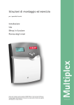
2.5
EMC Kit
For optimum EMC-compliant wiring, the optional EMC Kit must be used. This includes a shield
bracket, two hammer clips, two fastening screws and a pre-assembled PE cable. The PE cable must
be connected to the appropriate screw on the shielding bracket and to the PE terminal of the
frequency inverter. The connection of further PE connections to the shield bracket is possible with
additional ring cable lugs (SK EMC 2-1 and 2-2).
The EMC Kit provides the possibility of attaching the screening of the motor cable to a large surface of
the frequency inverter (interference source). If necessary, a screened brake resistor cable can be
attached with the second hammer clip.
The screening angle is attached to the two housing screws on the lower edge (below the U-V-W
terminals). The motor cable screening is earthed to a large area of the screening angle by means of
the hammer clip.
b
Similar to illustration
Fig. 4 EMC Kit SK EMC2-x
Device type
Size
SK 5xxE-250- … SK 5xxE-750-
Size 1
SK 5xxE-111- … SK 5xxE-221-
Size 2
SK 5xxE-301- … SK 5xxE-401-
Size 3
SK 5xxE-551-340- … SK 5xxE-751- 340-
Size 4
SK 5xxE-551-323- … SK 5xxE-751- 323SK 5xxE-112-340- … SK 5xxE-152- 340-
EMC Kit
Dimension "b"
SK EMC 2-1
Part No. 275999011
42 mm
SK EMC 2-2
Part No. 275999021
42 mm
Size 5
SK EMC 2-3
Part No. 275999031
52 mm
SK 5xxE-112-323SK 5xxE-182-340- … SK 5xxE-222- 340-
Size 6
SK EMC 2-4
Part No. 275999041
57 mm
SK 5xxE-152-323- … SK 5xxE-182- 323SK 5xxE-302-340- … SK 5xxE-372- 340-
Size 7
SK EMC 2-5
Part No. 275999051
57 mm
SK 5xxE-452-340- … SK 5xxE-902- 340-
Size 8/9
SK EMC 2-6
Part No. 275999061
100 mm
Table 4: EMC Kit SK EMC2-x
Note
The EMC Kit cannot be combined with ...-CP (ColdPlate) devices. Any cable screening must be earthed to a large
area of the mounting surface.
Alternatively, the EMC Kit can be simply used as a strain relief (e.g. for the connection cables of a bus system)
(note the bending radii!).
Pos : 36 /Anl eitungen/Elektroni k/FU und Starter/2. M ontage und Ins tall ati on/2.6 Brems wi derstand (BW) [BU 0500] @ 0\mod_1325862128510_388.doc x @ 5848 @ 2 @ 1
28
BU 0500 GB-1013
2 Assembly and installation
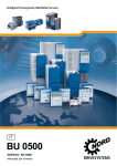
2.6
Brake resistor (BR)
CAUTION
Danger of burns
The heat sink and all other metal components can heat up to temperatures above 70°C.
Touching such components may cause local burns to the affected parts of the body (hands, fingers, etc.).
To prevent such injuries, allow sufficient time for cooling down before starting work - the surface temperature
should be checked with suitable measuring equipment. In addition, keep sufficient distance from adjacent
components during installation, or install protection against contact.
During dynamic braking (frequency reduction) of a three-phase motor, electrical energy is returned to
the inverter. An external brake resistor can be used in order to prevent the FI from being shut down
due to overvoltage. With this, the integrated brake chopper (electronic switch) pulses the intermediate
circuit voltage (switching wave approx. 420 V/775 V(/825 V) DC, according to the mains voltage)
(115 V, 230 V/400 V(/500 V)) to the brake resistor. Here the excess energy is converted into heat.
For inverter powers up to 7.5 kW (230 V: up to 4.0 kW) a standard bottom-mounted resistor
(SK BR4-..., IP40) can be used. This can additionally be equipped with an optional temperature switch
(bi-metal, switching point 100
℃), in order to i
is enclosed. The resistor and the temperature switch are connected by means of flexible stranded
conductors. Approval: UL, cUL
Note: Brake resistors cannot be directly mounted below …-CP (ColdPlate) devices.
SK BR4-... Size 1
SK BR4-... Size 2
For frequency inverters above 3kW chassis resistors (SK BR2-..., IP20) are also available. These
must be mounted in the control cabinet, close to the frequency inverter. There is a temperature switch
on the braking resistor to provide protection against overload. Connection of the resistor and the
temperature switch is by means of screw terminals. Approval: UL, cUL
SK BR2-... Size 3
SK BR2-... Size 4 and above
Fig. 5: Top: bottom-mounted brake resistor SK BR4- Bottom: chassis brake resistor SK BR2-...
Pos : 37 /Anl eitungen/Elektroni k/FU und Starter/2. M ontage und Ins tall ati on/2.6.1 Elektrische D aten BW [BU 0500] @ 0\mod_1325862333353_388.doc x @ 5871 @ 3 @ 1
BU 0500 GB-1013
29
SK 500E – Users Manual for Frequency Inverters
2.6.1
Electrical data, brake resistor
Inverter ID
Resistor type
Resistance
Continuous
rating
Pulse
energy*
SK 5xxE-250-112-O …
SK 5xxE-370-112-O
SK BR4-240/100
240 W
100 W
1.0 kWs
SK 5xxE-550-112-O …
SK 5xxE-750-112-O
SK BR4-150/100
150 W
100 W
1.0 kWs
SK 5xxE-250-323-A …
SK 5xxE-370-323-A
SK BR4-240/100
240 W
100 W
1.0 kWs
SK 5xxE-550-323-A …
SK 5xxE-750-323-A
SK BR4-150/100
SK 5xxE-111-323-A …
SK 5xxE-221-323-A
SK BR4- 75/200
SK 5xxE-301-323-A …
SK 5xxE-401-323-A
SK BR4- 35/400
SK 5xxE-301-323-A …
SK 5xxE-401-323-A
SK 5xxE-551-323-A …
SK 5xxE-751-323-A
SK BR2- 35/400-C
SK 5xxE-112-323-A
SK BR2- 12/1500-C
SK 5xxE-152-323-A …
SK 5xxE-182-323-A …
SK BR2- 9/2200-C
SK 5xxE-550-340-A …
SK 5xxE-750-340-A
SK BR4-400/100
SK 5xxE-111-340-A …
SK 5xxE-221-340-A
SK 5xxE-301-340-A …
SK 5xxE-401-340-A
SK 5xxE-551-340-A …
SK 5xxE-751-340-A
SK 5xxE-301-340-A …
SK 5xxE-401-340-A
SK 5xxE-551-340-A …
SK 5xxE-751-340-A
SK 5xxE-112-340-A …
SK 5xxE-152-340-A
SK 5xxE-182-340-A …
SK 5xxE-222-340-A
SK 5xxE-302-340-A …
SK 5xxE-372-340-A
SK 5xxE-452-340-A …
SK 5xxE-552-340-A
SK 5xxE-752-340-A …
SK 5xxE-902-340-A
SK BR4-220/200
Part No. 275991110
Part No. 275991115
Part No. 275991110
Part No. 275991115
Part No. 275991120
Connecting
cable /
terminals
2
2 x 1.9mm
AWG 14/19
L = 0.5m
2
150 W
100 W
1.0 kWs
75 W
200 W
3.0 kWs
2 x 1.9mm
AWG 14/19
L = 0.5m
2
Part No. 275991140
Part No. 278282045
SK BR2- 22/600-C
Part No. 278282065
Part No. 278282015
Part No. 278282122
Part No. 275991210
Part No. 275991220
SK BR4-100/400
Part No. 275991240
SK BR4-60/600
Part No. 275991260
SK BR2-100/400-C
Part No. 278282040
SK BR2- 60/600-C
Part No. 278282060
SK BR2- 30/1500-C
Part No. 278282150
SK BR2- 22/2200-C
Part No. 278282220
SK BR2- 12/4000-C
Part No. 278282400
SK BR2- 8/6000-C
Part No. 278282600
SK BR2- 6/7500-C
Part No. 278282750
35 W
400 W
6.0 kWs
2 x 2.5mm
AWG 14/19
L = 0.5m
35 W
400 W
6.0 kWs
2 x 10mm
2
22 W
600 W
7.5 kWs
2 x 10mm
2
12 W
1500 W
20 kWs
2 x 10mm
2
9W
2200 W
28 kWs
2 x 10mm
2
400 W
100 W
1.0 kWs
220 W
200 W
3.0 kWs
2 x 1.9mm
AWG 14/19
L = 0.5m
100 W
400 W
6.0 kWs
60 W
600 W
12.0 kWs
100 W
400 W
6.0 kWs
60 W
600 W
7.5 kWs
30 W
1500 W
20 kWs
22 W
2200 W
28 kWs
12 W
4000 W
52 kWs
8W
6000 W
78 kWs
6W
7500 W
104 kWs
2
2
2 x 2.5mm
AWG 14/19
L = 0.5m
2 x 10mm
2
2 x 10mm
2
2 x 25mm
2
*) Maximum once for 1.2s within 120s
Table 5: Electrical data for brake resistor SK BR2-… and SK BR4-…
The chassis brake resistors (SK BR2-…) listed above are equipped with a temperature switch at the
factory. An optional temperature switch is available for the bottom-mounted brake resistor
(SK BR4-…). In order to use the signal from the temperature switch it must be connected to a free
digital input of the frequency inverter and, for example, parameterised with the function "Voltage block"
or "Fast stop".
30
BU 0500 GB-1013
2 Assembly and installation
Bi-metal temperature switch
for...
Part No.
Protection
Voltage
class
Nominal
switching
temperature
Current
SK BR4-... 275991200
IP40
250Vac
2.5A with cosj=1
1.6A with cosj=0.6
SK BR2-...
IP00
250Vac
125Vac
30Vdc
10A
15A
5A
integrated
℃
100
180°C ± 5K
Dimensions
Connecting
cable /
terminals
Width +10mm
(one side)
Flexible
strand 2 x
2
0.8mm
AWG 18/19
L = 0.5m
Internal
terminals
2
2 x 4mm
Table 6: Brake resistor temperature switch data
Pos : 38 /Anl eitungen/Elektroni k/FU und Starter/2. M ontage und Ins tall ati on/2.6.2 Abmess ungen U nterbau- BW SK BR 4 [BU 0500] @ 0\mod_1325862485335_388.doc x @ 5894 @ 3 @ 1
2.6.2
Dimensions of bottom-mounted BR SK BR4
Fixing dimensions
Resistor type
Size
A
B
C
D
Æ
SK BR4-240/100
SK BR4-150/100
SK BR4-400/100
Size 1
230
88
175
220
5.5
SK BR4- 75/200
SK BR4-220/200
Size 2
270
88
175
260
5.5
SK BR4-35/400
SK BR4-100/400
Size 3
285
98
239
275
5.5
SK BR4-60/600
Size 4
330
98
239
320
5.5
C = Installation depth of the frequency inverter + bottom-mounted brake resistor.
All dimensions in mm
Table 7: Dimensions of bottom-mounted brake resistor SK BR4-...
A D
B
C
NORDAC SK 5xxE
B
SK BR4-... Size 2
A D
C
NORDAC SK 5xxE
SK BR4-... Size 1
Optional temperature switch
BU 0500 GB-1013
31
SK 500E – Users Manual for Frequency Inverters
Type plate
Type plate
Temperature switch optional
please order separately
For fitting by the customer
Temperature switch optional
please order separately
For fitting by the customer
SK BR4-... Size 3
SK BR4-... Size 4
Separate data sheets are available for bottom-mounted brake resistors SK BR4 above size 3. These
can be downloaded at www.nord.com.
Inverter ID
Brake resistor type
Part No.
Data sheet
SK 5xxE-301-323-A … -401-323-A
SK BR4-35/400
275991140
TI014 275991140
SK 5xxE-301-340-A … -401-340-A
SK BR4-100/400
275991240
TI014 275991240
SK 5xxE-551-340-A … -751-340-A
SK BR4-60/600
275991260
TI014 275991260
Pos : 39 /Anl eitungen/Elektroni k/FU und Starter/2. M ontage und Ins tall ati on/2.6.3 Abmess ungen C has sis-BW SK BR 2 [BU 0500, u.A.] @ 0\mod_1325862658505_388.doc x @ 5917 @ 3 @ 1
32
BU 0500 GB-1013
2 Assembly and installation
2.6.3
Dimensions, brake resistor chassis SK BR2
Fixing dimensions
Resistor type
A
SK BR2-100/400-C
SK BR2- 35/400-C
SK BR2- 60/600-C
SK BR2- 22/600-C
SK BR2- 30/1500-C
SK BR2- 12/1500-C
SK BR2- 22/2200-C
SK BR2- 9/2200-C
SK BR2- 12/4000-C
SK BR2- 8/6000-C
SK BR2- 6/7500-C
B
C
D
E
Æ
170
100
240
150
90
4.3
350
92
120
325
78
6.5
560
185
120
530
150
6.5
460
270
120
430
240
6.5
560
470
570
270
600
600
240
300
300
530
440
540
240
2x220
2x220
6.5
6.5
6.5
All dimensions in mm
C
B
E
D
A
SK BR2-... FI size 3 and above
(Schematic diagram, model varies
according to power)
Table 8: Dimensions of chassis brake resistor SK BR2-...
Pos : 40 /Anl eitungen/Elektroni k/FU und Starter/2. M ontage und Ins tall ati on/2.7 N etzdr oss el SK CI1 [BU 0500, u.A.] @ 0\mod_1325862740832_388.doc x @ 5940 @ 2 @ 1
BU 0500 GB-1013
33
SK 500E – Users Manual for Frequency Inverters
2.7
Mains choke SK CI1
To reduce input side current harmonics,
additional inductivity can be installed into
the line supply to the inverter.
L1 L12
L2 L22
L3 L32
These chokes are specified for a maximum
supply voltage of 230 V or 480 V at
50/60 Hz.
D
All chokes have a protection class
corresponding to IP00. The choke used
must therefore be installed in a control
cabinet.
For frequency inverters with an output of
45 kW or more, a line choke is
recommended where several devices are
being used, in order to avoid possible
adverse effects of one device on another.
L2
B2
L1
W1
Similar
to
illustration
In addition, the charging currents (mains voltage fluctuations) are significantly reduced.
Input choke 1 x 220 - 240 V
NORD
SK 500E
Type
0.25 ... 0.75hp
SK CI1-230/8-C
1.1 ... 2.2 kW
SK CI1-230/20-C
L1
Continuous
Inductance
current
Part. No.: 278999030
Part. No.: 278999040
W1
L2
B2
Installation
Inverter ID
D
Connection
Detail: Mounting
8A
2 x 1.0 mH
78
65
89
56
40
M4
4
20 A
2 x 0.4 mH
96
90
106
84
65
M6
10
2
All dimensions in [mm]
[mm ]
Table 9: Mains choke data for SK CI1-..., 1~ 240 V
Input choke 3 x 200 - 240 V
NORD
SK 500E
Type
0.25 ... 0.75hp
SK CI1-480/6-C
1.1 ... 1.5 kW
SK CI1-480/11-C
2.2 … 3.0 kW
SK CI1-480/20-C
4.0 … 7.5 kW
SK CI1-480/40-C
11 … 15 kW
SK CI1-480/70-C
18 kW
Part. No.: 276993006
Part. No.: 276993011
Part. No.: 276993020
Part. No.: 276993040
Part. No.: 276993070
SK CI1-480/100-C
Part. No.: 276993100
Continuous
Inductance
current
L1
W1
L2
B2
Installation
Inverter ID
D
Connection
Detail: Mounting
6A
3 x 4.88 mH
96
60
117
71
45
M4
4
11 A
3 x 2.93 mH 120
85
140
105
70
M4
4
20 A
3 x 1.47 mH 155
110
177
135
95
M5
10
40 A
3 x 0.73 mH 155
115
172
135
95
M5
10
70 A
3 x 0.47 mH 185
122
220
170
77
M6
35
100 A
3 x 0.29 mH 240
148
263
180
122
M6
35
All dimensions in [mm]
2
[mm ]
Table 10: Mains choke data for SK CI1-..., 3~ 240 V
34
BU 0500 GB-1013
2 Assembly and installation
Input choke 3 x 380 - 480 V
NORD
SK 500E
Type
0.55 ... 2.2 kW
SK CI1-480/6-C
3.0 ... 4.0 kW
SK CI1-480/11-C
5.5 ... 7.5 kW
SK CI1-480/20-C
11 ... 15 kW
SK CI1-480/40-C
18 ... 30hp
SK CI1-480/70-C
Part. No.: 276993006
Part. No.: 276993011
Part. No.: 276993020
Part. No.: 276993040
Part. No.: 276993070
37 … 45 kW
SK CI1-480/100-C
55 … 75 kW
SK CI1-480/160-C
90 kW
SK CI1-480/280-C
Part. No.: 276993100
Part. No.: 276993160
Part. No.: 276993280
Continuous
Inductance
current
L1
W1
L2
B2
Installation
Inverter ID
D
Connection
Detail: Mounting
6A
3 x 4.88 mH
96
60
117
71
45
M4
4
11 A
3 x 2.93 mH
120
85
140
105
70
M4
4
20 A
3 x 1.47 mH
155
110
177
135
95
M5
10
40 A
3 x 0.73 mH
155
115
172
135
95
M5
10
70 A
3 x 0.47 mH
185
122
220
170
77
M6
35
100 A
3 x 0.29 mH
240
148
263
180
122
M6
35
160 A
3 x 0.18 mH
352
140
268
240
105
M8
M8*
280 A
3 x 0.10 mH
352
169
268
240
133
M10
M16*
All dimensions in [mm]
2
[mm ]
* Bolt for copper rail
Table 11: Mains choke data for SK CI1-..., 3~ 480 V
Pos : 41 /Anl eitungen/Elektroni k/FU und Starter/2. M ontage und Ins tall ati on/2.8 Ausgangsdr ossel SK C O1 [BU 0500, u.A.] @ 0\mod_1325863040983_388.doc x @ 5963 @ 2 @ 1
BU 0500 GB-1013
35
SK 500E – Users Manual for Frequency Inverters
2.8
Output choke SK CO1
To reduce interference signals from the
motor cable or to compensate for cable
capacitance in long motor cables, an
additional output choke can be installed
into the inverter output.
U U2
V V2
W W3
During installation take care that the pulse
frequency of the frequency inverter is set
to 3 - 6 kHz (P504 = 3 - 6).
D
These chokes are specified for a
maximum supply voltage of 480 V at
0 - 100 Hz.
L2
B2
L1
W1
Similar
to
illustration
Output choke 3 x200 – 240 V
Detail: Mounting
NORD
SK 5xxE
Type
0.25 … 0.75
kW
SK CI1-460/4-C
1.1 ... 1.5 kW
SK CI1-460/9-C
2.2 ... 4.0 kW
SK CI1-460/17-C
5.5 ... 7.5 kW
SK CI1-460/33-C
11 … 15 kW
SK CI1-480/60-C
18 kW
SK CI1-460/90-C
Part. No.: 276996004
Part. No.: 276996009
Part. No.: 276996017
Part. No.: 276996033
Part. No.: 276992060
Part. No.: 276996090
Continuous
Inductance
current
L1
W1
L2
B2
Installation
Inverter ID
D
Connection
An output choke should be fitted for cable lengths over 100 m/30 m (unshielded/shielded). All chokes
have a protection class corresponding to IP00. The choke used must therefore be installed in a control
cabinet.
4A
3 x 3.5 mH
120
104
140
84
75
M6
4
9A
3 x 2.5 mH
155
110
160
130
71.5
M6
4
17 A
3 x 1.2 mH
185
102
201
170
57.5
M6
10
33 A
3 x 0.6 mH
185
122
201
170
77.5
M6
10
60 A
3 x 0.33 mH
185
112
210
170
67
M8
16
90 A
3 x 0.22 mH
352
144
325
224
94
M10
35
All dimensions in [mm]
[mm2]
Table 12: Output choke data for SK CO1-..., 3~ 240 V
36
BU 0500 GB-1013
2 Assembly and installation
Output choke 3 x 380 – 480 V
Connection
Detail: Mounting
NORD
SK 5xxE
Type
0.55 ... 1.5 kW
SK CI1-460/4-C
2.2 ... 3.0 kW
SK CI1-460/9-C
4.0 ... 7.5 kW
SK CI1-460/17-C
11 ... 15 kW
SK CI1-460/33-C
18 ... 30hp
SK CI1-480/60-C
37 … 45 kW
SK CI1-460/90-C
55 … 75 kW
SK CI1-460/170-C
90 kW
SK CI1-460/240-C
Continuous
Inductance
current
Part. No.: 276996004
Part. No.: 276996009
Part. No.: 276996017
Part. No.: 276996033
Part. No.: 276992060
Part. No.: 276996090
Part. No.: 276996170
Part. No.: 276996170
L1
W1
L2
B2
Installation
Inverter ID
D
4A
3 x 3.5 mH
120
104
140
84
75
M6
4
9A
3 x 2.5 mH
155
110
160
130
71.5
M6
4
17 A
3 x 1.2 mH
185
102
201
170
57.5
M6
10
33 A
3 x 0.6 mH
185
122
201
170
77.5
M6
10
60 A
3 x 0.33 mH
185
112
210
170
67
M8
16
90 A
3 x 0.22 mH
352
144
325
224
94
M10
35
170 A
3 x 0.13 mH
412
200
320
264
125
M10
M12*
240 A
3 x 0.07 mH
412
225
320
388
145
M10
M16*
All dimensions in [mm]
[mm2]
* Bolt for copper rail
Table 13: Output choke data for SK CO1-..., 3~ 480 V
Pos : 42 /Anl eitungen/Elektroni k/FU und Starter/2. M ontage und Ins tall ati on/2.9 N etzfilter [BU 0500] @ 0\mod_1325863166231_388.doc x @ 5986 @ 2 @ 1
2.9
Line filter
An additional external line filter can be installed into the line supply of the frequency inverter to
maintain the increased noise suppression level (class B as per EN 55011).
Pos : 43 /Anl eitungen/Elektroni k/FU und Starter/2. M ontage und Ins tall ati on/2.9 N etzfilter -Teil 1 - N etz filter SK NHD [BU 0500] @ 1\mod_1331135215479_388.doc x @ 17490 @ 5 @ 1
Mains filter SK NHD (up to size 4)
SK NHD type mains filters are so-called bottom-mounted combination filters with integrated mains
choke. The mains filter is only intended for three-phase operation.
This provides a compact unit to improve the level of radio interference suppression, which can also be
mounted underneath the frequency inverter if there is a shortage of space.
For further information about the overvoltage filter, please refer to the relevant data sheet. These data
sheets can be downloaded from www.nord.com.
Inverter ID
Filter type
Part No.
Data sheet
SK 5xxE-250-323-A … -750-323-A
SK NHD-480/6-F
278273006
TI030 278273006
SK 5xxE-111-323-A … -221-323-A
SK NHD-480/10-F
278273010
TI030 278273010
SK 5xxE-301-323-A … -401-323-A
SK NHD-480/16-F
278273016
TI030 278273016
SK 5xxE-550-340-A … -750-340-A
SK NHD-480/3-F
278273003
TI030 278273003
SK 5xxE-111-340-A … -221-340-A
SK NHD-480/6-F
278273006
TI030 278273006
SK 5xxE-301-340-A … -401-340-A
SK NHD-480/10-F
278273010
TI030 278273010
SK 5xxE-551-340-A … -751-340-A
SK NHD-480/16-F
278273016
TI030 278273016
Table 14: Mains filter NHD-...
Pos : 44 /Anl eitungen/Elektroni k/FU und Starter/2. M ontage und Ins tall ati on/2.9 N etzfilter -Teil 2 - N etz filter SK LF2 [BU 0500] @ 1\mod_1331135342246_388.doc x @ 17514 @ 5 @ 1
BU 0500 GB-1013
37
SK 500E – Users Manual for Frequency Inverters
Mains filter SK LF2 (size 5 - 6)
SK LF2 type mains filters are mains filters which can be bottom mounted, and their dimensions are
matched to those of the relevant frequency inverter. This enables space-saving installation.
Inverter ID
Filter type
Part No.
Data sheet
SK 5xxE-551-323-A … -751-323-A
SK LF2-480/45-F
278273045
TI030 278273045
SK 5xxE-112-323-A
SK LF2-480/66-F
278273066
TI030 278273066
SK 5xxE-112-340-A … -152-340-A
SK LF2-480/45-F
278273045
TI030 278273045
SK 5xxE-182-340-A … -222-340-A
SK LF2-480/66-F
278273066
TI030 278273066
Table 15: Mains filter LF2-...
Pos : 45 /Anl eitungen/Elektroni k/FU und Starter/2. M ontage und Ins tall ati on/2.9 N etzfilter -Teil 3 - N etz filter SK HLD [BU 0500] @ 1\mod_1331135394656_388.doc x @ 17538 @ 5 @ 1
Mains filter SK HLD (above size 5)
B2
L1 L
2 L3
In addition, a chassis mains filter is available for inverters of size V and above. This
enables Class Bradio interference suppression up to a maximum motor cable length
of 25 m.
Netz /
LINE
When connecting the line filter, comply with "Wiring guidelines" Section 2.10.1 and
"EMC" Section 8.3. In particular, care must be taken that the pulse frequency is set
to the default value (P504 = 6kHz). The line filter should be placed as close to the
side of the inverter as possible.
The connection is by means of screw connections on the upper (mains) and lower
(inverter) ends of the filter
L2 L1
Gerät
/ LOAD
L1' L
2' L3'
T
B1
Filter type
[-V/A]
Inverter ID
Detail: Mounting
L1
W1
D
L2
B2
Connection
crosssection
SK 5xxE-551-323-A
SK HLD 110-500/30
270
55
95
255
30
10
SK 5xxE-751-323-A
SK HLD 110-500/42
310
55
95
295
30
10
SK 5xxE-112-323-A
SK HLD 110-500/75
270
85
135
255
60
35
SK 5xxE-152-323-A…
SK 5xxE-182-323-A
SK HLD 110-500/100
270
95
150
255
65
50
SK 5xxE-112-340-A…
SK 5xxE-152-340-A
SK HLD 110-500/42
310
55
95
295
30
10
SK 5xxE-182-340-A
SK HLD 110-500/55
250
85
95
235
60
16
SK 5xxE-222-340-A
SK HLD 110-500/75
270
85
135
255
60
35
SK 5xxE-302-340-A…
SK 5xxE-372-340-A
SK HLD 110-500/130
270
95
150
255
65
50
SK 5xxE-452-340-A…
SK 5xxE-552-340-A
SK HLD 110-500/180
380
130
181
365
102
95
SK 5xxE-752-340-A…
SK 5xxE-902-340-A
SK HLD 110-500/250
450
155
220
435
125
150
All dimensions in mm
Table 16: Mains filter HLD-...
Pos : 46 /Anl eitungen/Elektroni k/FU und Starter/2. M ontage und Ins tall ati on/2.9 N etzfilter -Teil 4 - Spannungsbegrenz ungsfilter SK CIF [BU 0500] @ 0\mod_1325863390898_388.doc x @ 6009 @ 5 @ 1
38
BU 0500 GB-1013
mm2
2 Assembly and installation
Voltage limitation filter SK CIF
Up to and including size 6, the use of a suitable overvoltage filter is mandatory (see also Section 1.5)
in order to comply with cUL requirements. For further information about the overvoltage filter, please
refer to the relevant data sheet. These data sheets can be downloaded from www.nord.com.
Inverter ID
Filter type
Part No.
Data sheet
SK 5xxE-250-323-A … -301-323-A*
SK CIF-323-20
276997070
TI030 276997070
SK 5xxE-401-323-A … -112-323-A*
SK CIF-323-40
276997071
TI030 276997071
SK 5xxE-550-340-A … -751-340-A
SK CIF-340-30
276997080
TI030 276997080
SK 5xxE-112-340-A … -222-340-A
SK CIF-340-60
276997081
TI030 276997081
* (only with suitable mains choke)
Table 17: Mains filter SK CIF-...
Pos : 47 /Anl eitungen/Elektroni k/FU und Starter/2. M ontage und Ins tall ati on/2.10 Elektrischer Ansc hl uss [BU 0500] @ 0\mod_1325863603644_388.doc x @ 6055 @ 2 @ 1
BU 0500 GB-1013
39
SK 500E – Users Manual for Frequency Inverters
2.10 Electrical connections
WARNING
THESE DEVICES MUST BE EARTHED.
Safe operation of the devices presupposes that qualified personnel mount and operate it in compliance with the
instructions provided in these operating instructions.
In particular, the general and regional installation and safety regulations for work on high voltage systems (e.g.
VDE) must be complied with as must the regulations concerning correct use of tools and the use of personal
protection equipment.
Dangerous voltages can be present at the motor connection terminals even when the inverter is switched off.
Always use insulated screwdrivers on these terminal fields.
Ensure that the input voltage source is not live before setting up or changing connections to the unit.
Make sure that the inverter and motor have the correct supply voltage set.
Note
Thermistor
As with other signal cables, thermistor cables must be laid separately from the motor cables
Depending on the size of the frequency inverter, the connection terminals for the supply cables and
the control cables are located in different positions. According to the configuration of the frequency
inverter, various terminals are not present.
Size 1 - 4
1=
2=
3=
4=
5=
6=
7=
8=
40
Mains connection
Motor connection
multi-function relay
Braking resistor
DC - link circuit
Control terminals
Technology unit
Link circuit choke
Size 5 - 7
L1, L2/N, L3, PE
U, V, W, PE
1-4
+B, -B
-DC
IOs, GND, 24Vout, IG, DIP for AIN
-DC, CP, PE
Above size 8
X1
X2
X3
X2
X2
à
Above Size 8: + DC, - DC
X4, X5, X6, X7, X14
Above size 8:
BU 0500 GB-1013
2 Assembly and installation
Size 1 - 4
9=
10 =
11 =
12 =
communication
Thermistor
Safe pulse block
Control voltage VI 24V
Size 5 - 7
CAN/CANopen; RS232/RS485
T1/2 or TF+/86, 87, 88, 89
40, 44
Above size 8
à
X13
X8
X12
X9/X10; X11
Up to size 4 (except SK 54xE): to DIN 5
Except SK 5x0E and SK 511E
Pos : 48 /Anl eitungen/Elektroni k/FU und Starter/2. M ontage und Ins tall ati on/2.10.1 Ver drahtungsrichtlini en [Allg.] @ 0\mod_1325863475147_388.doc x @ 6032 @ 3 @ 1
2.10.1 Wiring guidelines
The frequency inverters have been developed for use in an industrial environment. In this
environment, high levels of electromagnetic interference can act on the frequency inverter. In general,
correct installation ensures safe and problem-free operation. To meet the limiting values of the EMC
directives, the following instructions should be complied with.
1. Ensure that all equipment in the control cabinet is securely earthed using short earthing cables
which have large cross-sections and are connected to a common earthing point or earthing bar. It
is especially important that each control unit which is connected to the electronic drive technology
(e.g. an automatic device) has a short cable with a large cross-section, which is connected to the
same earthing point as the dfrequency inverter itself. Flat cables (e.g. metal stirrups) are
preferable, as they have a lower impedance at high frequencies.
2. The bonding cable of the motor controlled by the frequency inverter should be connected directly to
the earthing terminal of the associated controller. The presence of a central earthing bar in the
control cabinet and the grouping together of all bonding conductors to this bar normally ensures
safe operation.
3. Where possible, shielded cables should be used for control circuits. The shielding at the cable end
should be carefully sealed and it must be ensured that the wires are not laid over longer distances
without shielding.
The shields of analog setpoint cables should only be earthed on one side on the device.
4. The control cables should be installed as far as possible from power cables, using separate cable
ducts, etc. Where cables cross, an angle of 90° should be ensured as far as possible.
5. Ensure that the contactors in the cabinet are interference protected, either by RC circuits in the
case of AC contactors or by free-wheeling diodes for DC contactors, for which the interference
traps must be positioned on the contactor coils. Varistors for over-voltage limitation are also
effective. This interference suppression is particularly important when the contactors are controlled
by the relay in the frequency inverter.
6. Shielded or armoured cables should be used for the load connections (motor cable). The shielding
or armouring must be earthed at both ends. If possible, earthing should be made directly to the
electrically conducting mounting plate of the control cabinet or the screening angle of the EMC Kit.
BU 0500 GB-1013
41
SK 500E – Users Manual for Frequency Inverters
In addition, EMC-compliant wiring must be ensured. If required, an optional output choke can be
supplied
The safety regulations must be complied with under all circumstances when installing the
frequency inverter!
NOTICE
Interference and damage
The control cables, mains cables and motor cables must be laid separately. Under no circumstances may they be
installed in a common conduit or installation duct, in order to prevent interference.
The test equipment for high voltage insulations must not be used on cables that are connected to the motor
controller. Failure to comply with this will cause damage to the drive electronics.
Pos : 49 /Anl eitungen/Elektroni k/FU und Starter/2. M ontage und Ins tall ati on/2.10.2 Anpassung an IT-Netz e [BU 0500] @ 1\mod_1331196207398_388.doc x @ 17782 @ 355 @ 1
2.10.2 Adaptation to IT networks
As delivered, the device is configured for operation in TN or TT networks. Simple adaptations must be
made for operation in an It network. However, these adaptations also cause a deterioration in the
suppression of radio interference.
Up to and including size 7, the adaptation is made with jumpers. As delivered, the jumpers are set in
the “normal position”. With this, the mains filter has its normal effect and leakage current. From size 8
and above there is a DIP switch element. According to the setting of the DIP switch, the frequency
inverter is configured for TN/TT network operation or for operation in an IT network (also refer to
Sections Fehler! Verweisquelle konnte nicht gefunden werden. and 0).
Frequency inverter
Jumper A
Jumper B
Remarks
Leakage current
Size 1 - 4
Position 1
Position 1
Operation in IT network
Not applicable
Size 1 - 4
Position 3
Position 2
Large filtering effect
< 30 mA
Size 1 - 4
Position 3
Position 3
Limited effect of filter
<< 30 mA
> 3.5 mA
Size 5 - 6
Position 0
Position 1
Operation in IT network
Size 5 - 6
Position 4
Position 2
Large filtering effect
Size 7
Position 0
Position 1
Operation in IT network
Size 7
Position 4
Position 2
Large filtering effect
Not applicable
< 6 mA
Not applicable
< 6 mA
DIP switch "EMC-Filter"
Size 8 - 9
OFF
Operation in IT network
< 30 mA
Size 8 - 9
ON
Large filtering effect
< 10 mA
Table 18: Integrated mains filter
Adaptation of sizes 1 - 7
NOTICE
Jumper positions
Jumper positions which are not illustrated below must not be used, as these may cause the destruction of the
frequency inverter.
42
BU 0500 GB-1013
2 Assembly and installation
Jumper “A” mains input
Size 1 - 4
Top side of device
= Operation in IT network = Position 1
(reduced leakage current)
= normal position = Position 3
Size 5 - 7
= Operation in IT network = Position 0
(reduced leakage current)
Geräte- Oberseite
= normal position = Position 4
Jumper 'B' motor output
Size 1 - 4
Underside of the device
= Operation in IT network = Position 1
= normal position = Position 2
= reduced leakage current – Position 3
(The set pulse frequency (P504) only has a slight
influence on the leakage current.)
Size 5 - 7
Underside of the device
= Operation in IT network = Position 1
(reduced leakage current)
= normal position = Position 2
BU 0500 GB-1013
43
SK 500E – Users Manual for Frequency Inverters
Adaptation above size 8
The adaptation to the IT network is carried out via the DIP
switch "EMC Filter" (1). As delivered, this switch is in the "ON"
position.
For operation in an IT network the switch must be set to the
"OFF" position. The leakage current is reduced, with a
deterioration in the EMC compatibility.
Pos : 50 /Anl eitungen/Elektroni k/FU und Starter/2. M ontage und Ins tall ati on/2.10.3 Gl eic hspannungs koppl ung [BU 0500] @ 1\mod_1331196183481_388.doc x @ 17758 @ 3 @ 1
2.10.3 DC-coupling
NOTICE
Overload of link circuits
It is essential to note the following summary of criteria for the setup of a DC supply or the coupling of the link
circuits of frequency inverters.
Errors in the link circuit coupling have especially negative effects on the charging circuits in the inverters or on the
life span of the link circuits - including their complete destruction.
In drive engineering, DC-coupling is advisable if motors act as drivers and generators at the same
time in the system. Here, the energy from the drive which is acting as a generator can be fed back to
the drive which is acting as a motor. The advantages are lower energy consumption and the sparing
use of braking resistors. In addition, the energy balance can be made even more efficient with the use
of a regenerative feedback unit or an input/feedback unit. In general, in case of DC coupling, wherever
possible, devices with the same power should be connected together. Furthermore, only operational
devices (whose link circuits are charged) must be coupled.
Connection
NOTICE
Size 1 … 7
+B, - DC
Above size 8:
+ DC, - DC
DC coupling for single phase devices
For direct current coupling of single-phase devices, care must be taken that the coupling to the same external
conductor is used. Otherwise the device may be destroyed.
For the 115V devices (SK 5xx-xxx-112-O), no DC coupling is possible.
44
BU 0500 GB-1013
2 Assembly and installation
L1 / L
L2 / N
L3 / PE
PE L3 L2 L1
PE L3 L2 L1
U1
Readiness
message from
all FIs
PE U V W +B -B -DC
U2
PE U V W +B -B -DC
Coupling if
FIs ready
M
3~
M
3~
Fig. 6 Diagram of a DC-coupling
1 The link circuits of the individual frequency inverters must be protected with suitable fuses.
2 The frequency inverters only obtain their power supply via the link circuit. Electrical isolation is
carried out via the power circuit breakers which must be provided in the supplies to the devices.
3 CAUTION! Ensure that the coupling is only made after readiness is reported. Otherwise, there
is a danger that all the frequency inverters will be charged by a single one.
4 Ensure that the coupling is disconnected as soon as one of the devices is no longer ready for
operation.
5 For a high availability a braking resistor must be used. If different sizes of frequency inverters
are used, the braking resistor must be connected to the larger of the two frequency inverters.
6 If devices with the same rating (identical type) are coupled, and the same mains impedances
are in effect (identical lengths of cable to the mains rail), the frequency inverters may be
operated without mains chokes. Otherwise a mains choke must be installed in the mains cable
of each frequency inverter.
BU 0500 GB-1013
45
SK 500E – Users Manual for Frequency Inverters
L1 / L
L2 / N
L3 / PE
PE L3 L2 L1
PE L3 L2 L1
PE U V W +B -B -DC
PE U V W +B -B -DC
PE L3 L2 L1
Input/feedback
unit
For information on
connection and
protection, as well as the
necessary accessories,
please consult the
manufacturer of the
input/feedback unit.
+
-
M
3~
M
3~
Fig. 7 Diagram of a DC coupling with an input/feedback unit
The following points must be taken into consideration in association with a DC supply:
1 Use a connecting cable which is as short as possible between the DC bus and the equipment to
be connected. The connection and protection of the devices in the DC circuit must be carried
out for cable protection and the maximum cross-section of the device.
2 The link circuits of the individual frequency inverters must be protected with suitable fuses.
3 The frequency inverters only obtain their supply via the link circuit. Electrical isolation is carried
out via the power circuit breakers which must be provided in the supplies to the devices.
4 For frequency inverters above size 8, a DC supply is only permissible with an external charging
device.
Pos : 51 /Anl eitungen/Elektroni k/FU und Starter/2. M ontage und Ins tall ati on/2.10.4 Elektrischer Ansc hluss Leis tungsteil [BU 0500] @ 0\mod_1325863684752_388.doc x @ 6078 @ 3 @ 1
46
BU 0500 GB-1013
2 Assembly and installation
2.10.4 Electrical connections, power unit
Before connecting the frequency inverter, the following must be observed:
1. Ensure that the mains supply provides the correct voltage and is suitable for the current required.
2. Ensure that suitable circuit breakers with the specified nominal current range are installed between
the voltage source and the inverter.
3. Connect the mains voltage directly to the mains terminals L1-L2/N-L3-PE (for each device)
4. A four-core cable must be used to connect the motor. The cable is connected to the motor
terminals PE-U-V-W.
5. If screened motor cables (recommended) are used, the cable screening must also be connected to
a large area of the metallic screening angle of the EMC Kit, however, at least to the electrically
conducting mounting surface of the control cabinet.
6. Above size 8, the cable lugs which are included in the scope of delivery must be used. After
crimping, these must be insulated with shrink hose.
Note
The use of shielded cables is essential in order to maintain the specified radio interference suppression level.
If certain wire end sleeves are used, the maximum cross-section which can be connected can be reduced.
To connect the power unit, the following tools must be used:
Frequency inverter
Tools
Type
Size 1 - 4
Screwdriver
SL / PZ1; SL / PH1
Size 5 - 7
Screwdriver
SL / PZ2; SL / PH2
Size 8 - 9
Socket wrench
SW 13
Table 19: Tools
Connection data:
Frequency inverter
BG 1 ... 4
Size 5
Size 6
Size 7
Size 8
Size 9
Rigid cable Ø
[mm²]
0.2 … 6
0.5 … 16
0.5 … 35
0.5 … 50
50
95
Flexible cable Ø
[mm²]
0.2 … 4
0.5 … 10
0.5 … 25
0.5 … 35
50
95
24-10
20-6
20-2
20-1
1/0
3/0
[Nm]
0.5 … 0.6
1.2 … 1.5
2.5 … 4.5
2.5 … 4
15
15
[lb-in]
4.42 … 5.31
10.62 … 13.27
22.12 … 39.82
22.12 … 35.4
135
135
AWG standard
Starting torque
Table 20: Connection data
NOTICE
Brake voltage supply
The voltage supply for an electro-mechanical brake (or its brake rectifier) must be via the mains.
Connection to the output side (connection to the motor terminals) may cause the destruction of the brake or the
frequency inverter.
Pos : 52 /Anl eitungen/Elektroni k/FU und Starter/2. M ontage und Ins tall ati on/2.10.4 Elektrischer Ansc hluss Leis tungsteil -Teil 1 - N etz ansc hlus s (X1) [BU 0500] @ 1\mod_1331195429990_388.doc x @ 17590 @ 5 @ 1
BU 0500 GB-1013
47
SK 500E – Users Manual for Frequency Inverters
Mains connections (X1 – PE, L1, L2/N, L3)
No special safety measures are required on the mains input side of the frequency inverter. It is
advisable to use the normal mains fuses (see technical data) and a main switch or circuit breaker.
Frequency inverter data
Voltage
Power
115 VAC
0.25 … 0.75 kW
230 VAC
0.25 … 2.2 kW
230 VAC
≥ 3.0 kW
400 VAC
≥ 0.37 kW
Connections
Permissible mains data
1 ~ 115 V
1 ~ 230 V
3 ~ 230 V
X
X
3 ~ 400 V
X
X
X
L/N = L1/L2
L/N = L1/L2
L1/L2/L3
L1/L2/L3
Isolation from or connection to the mains must always be carried out for all the poles and
synchronously (L1/L2/L2 or. L1/N).
NOTICE
Operation in IT networks
The use of this frequency inverter on an IT network is possible after modification of the integrated mains filter.
It is urgently recommended that the frequency inverter is only operated on a IT network if a braking resistor is
connected. If an earthing fault occurs in the IT network, this measure prevents an impermissible charging of the
link circuit capacitor and the associated destruction of the frequency inverter.
For operation with an insulation monitor, the insulation resistance of the frequency inverter must be taken into
account.
Pos : 53 /Anl eitungen/Elektroni k/FU und Starter/2. M ontage und Ins tall ati on/2.10.4 Elektrischer Ansc hluss Leis tungsteil -Teil 2 - M otor kabel (X2) [BU 0500] @ 1\mod_1331195941727_388.doc x @ 17638 @ 5 @ 1
Motor cable (X2 - U, V, W, PE)
The motor cable may have a total length of 100m if this is a standard cable (take EMC into
consideration). If a screened motor cable is used, or if the cable is laid in a metal conduit which is well
earthed, the total length should not exceed 30m.
For greater lengths of cable, an additional output choke (accessory) must be used.
For multiple motor operation the total motor cable length consists of the sum of the individual cable
lengths.
NOTICE
Output switching
The motor cable must not be switched as long as the inverter is pulsing (The inverter must be in "Standby" or
"Starting disabled" status).
Otherwise the inverter nay be damaged.
Pos : 54 /Anl eitungen/Elektroni k/FU und Starter/2. M ontage und Ins tall ati on/2.10.4 Elektrischer Ansc hluss Leis tungsteil -Teil 3 - Brems wi derstand (X2) [BU 0500] @ 1\mod_1331195973501_388.doc x @ 17662 @ 5 @ 1
Breake resistor (X2 - +B, -B)
The terminals +B/ -B are intended for the connection of a suitable braking resistor. A short screened
connection should be selected. For the installation of a braking resistor, the large amount of heat
which is generated due to its operation (> 70°C) must be taken into account.
Pos : 55 /Anl eitungen/Elektroni k/FU und Starter/2. M ontage und Ins tall ati on/2.10.5 Elektrischer Ansc hluss Steuerteil [BU 0500] @ 0\mod_1325864707420_388.doc x @ 6124 @ 3 @ 1
48
BU 0500 GB-1013
2 Assembly and installation
2.10.5 Electrical connections, control unit
The control connections are located under the front cover (above size 8 under the two front covers) of
the frequency inverter. The configuration differs according to the size. Up to size 7, the individual
control terminals (X3, X8, X13) are in staggered positions (please also refer to Section 2.10).
Connection data:
Frequency inverter
Terminal block
All
Size 1 … 4
Size 5 … 7
Above
size 8:
Typically
X3
X3, X8,
X12, X13
X3.1/2,
X15
Rigid cable Ø
[mm²]
0.14 … 1.5
0.14 … 2.5
0.2 … 6
0.2 … 2.5
Flexible cable Ø
[mm²]
0.14 … 1.5
0.14 … 1.5
0.2 … 4
0.2 … 2.5
26-16
26-14
24-10
24-12
Clamping
0.5 … 0.6
0.5 … 0.6
Clamping
4.42 … 5.31
4.42 … 5.31
AWG standard
Starting torque
[Nm]
[lb-in]
GND/0V is a common reference potential for analog and digital inputs.
Furthermore, it must be taken into account that with SK 5x5E size 1 ... 4 frequency inverters, terminal
44 is used to feed in the control voltage. However with devices of size 5 and above, this terminal
provides a 24V control voltage.
NOTICE
Cable laying
All control cables (including the thermistor) must be laid separately from the mains and the motor cables, in order
to prevent interference to the inverter.
If the cable are laid in parallel, a minimum distance of 20cm must be maintained from cables which carry a
voltage >60V The minimum distance may be reduced by screening the cables which carry a voltage, or by the
use of earthed metal partitions within the cable conduits.
NOTICE
Total currents
5V / 15V (24V) can be obtained from several terminals if required. With size 1 ... 4, the total output current must
not exceed 250mA/150mA (5V/15V). Above Size 5 the limiting value is 250mA/200mA (5V/24V).
Pos : 56 /Anl eitungen/Elektroni k/FU und Starter/2. M ontage und Ins tall ati on/2.10.5 Elektrischer Ansc hluss Steuerteil- Klemmenbl oc k X3 - R elais [SK 500...535E] @ 1\mod_1341401431286_388.doc x @ 29221 @ 5 @ 1
BU 0500 GB-1013
49
SK 500E – Users Manual for Frequency Inverters
Terminal block X3, (above size 8: X3.1 and X3.2) - Relay
Relevance
Terminals X3:
Name
SK 500E
SK 505E
SK 510E
SK 511E
SK 515E
SK 520E
SK 530E
SK 535E
√
√
√
√
√
√
√
√
1
2
3
4
K1.1
K1.2
K2.1
K2.2
Terminal Function
[Factory setting]
Data
Description / wiring suggestion
Parameter
1
2
Output 1
[Braking control]
Brake control
(closes on enabling)
P434
3
4
Output 2
[Ready/Fault]
Relay closing contact
230 VAC, 24 VDC,
< 60 VAC in circuits with
safe isolation,
≤2A
Fault / Ready
(closes when FI ready / no fault)
P441
Pos : 58 /Anl eitungen/Elektroni k/FU und Starter/2. M ontage und Ins tall ati on/2.10.5 Elektrischer Ansc hluss Steuerteil- Klemmenbl oc k X4 – Analog I/O [SK 500...535E] @ 1\mod_1341401660718_388.doc x @ 29265 @ 55 @ 1
Terminal block X4 – Analog I/O
Relevance
Terminals X4:
Name
SK 500E
SK 505E
SK 510E
SK 511E
SK 515E
SK 520E
SK 530E
SK 535E
√
√
√
√
√
√
√
√
11
12
14
16
17
VO 10V
GND/0V
AIN1
AIN2
AOUT1
Terminal
Function
[factory setting]
11
10V Reference
voltage
10V, 5mA
Reference potential
for analog signals
0V analog
12
14
16
17
Data
Analog input 1
V=0...10V, Ri=30kW,
[set point frequency] I=0/4...20mA, Ri=250W,
can be switched over with
Analog input 2
DIP switch, reference
[no function] voltage GND.
For the use of digital
functions 7.5...30V.
Above Size 5:
also -10 … + 10 V signals
Analog output
0...10V
[no function] Reference potential GND
Max. load current:
5mA analog,
20mA digital
Description / wiring suggestion
Parameter
The analog input controls the output
frequency of the frequency inverter.
11
12
14
16
17
R=10k
P400
The possible digital functions are
described in Parameter P420.
Above Size 5:
Configuration of analog input with DIP
switch (see below)
Can be used for an external display or
for further processing in a following
machine.
P405
P418
Pos : 60 /Anl eitungen/Elektroni k/FU und Starter/2. M ontage und Ins tall ati on/2.10.5 Elektrischer Ansc hluss Steuerteil- Klemmenbl oc k X5 – Digital In [SK 500...535E] @ 1\mod_1341401782175_388.doc x @ 29289 @ 5 @ 1
50
BU 0500 GB-1013
2 Assembly and installation
Terminal block X5 – Digital In
SK 500E
Relevance
SK 505E
√
Terminals X5:
Name
SK 510E
SK 511E
√
√
SK 515E
22
24
25
√
23
24
25
42
40
41
DIN1
DIN2
DIN3
DIN4
DIN5
VO 15V
GND/0V
VO 5V
Digital input 1
7.5...30V, Ri=6.1kW
[ON right]
Not suitable for thermistor
evaluation.
Digital input 2
HTL encoders can only be
Digital input 3
connected to DIN2 and
[parameter set bit0] DIN4
Limiting frequencies:
Digital input 4
10 kHz
[Fixed frequency 1, max.
min.
15 Hz
P429]
Description / wiring suggestion
15V output power
supply
21
22
23
24
25
42
40
41
42
40
41
P421
P422
15V
P423
motor - PTC
P424
7.5 … 30V
GND / 0V
motor - PTC
15V ± 20%
Supply voltage provided by the
frequency inverter for connection to the
digital inputs or the supply of a 10-30V
encoder.
40
Reference potential
for digital signals
0V digital
Reference potential
41
5V output power
supply
5V ± 20%
Voltage supply for motor-PTC
BU 0500 GB-1013
Parameter
P420
Each digital input has a reaction time of
≤ 5ms.
Connection with internal 15V:
Digital input 5
Connection with external 7,5-30V:
2.5...30V, Ri=2.2kW
[no function] Not suitable for evaluation
21
of a safety device.
22
23
Suitable for thermistor
24
evaluation with 5V.
25
NOTE: For the motor
thermistor P424 = 13 must
be set.
42
√
SK 535E
22
[ON left]
23
SK 530E
21
Terminal Function
Data
[factory setting]
21
SK 520E
51
SK 500E – Users Manual for Frequency Inverters
SK 500E
SK 505E
Relevance
SK 511E
SK 515E
√
Terminals X5:
Name
SK 510E
22
SK 530E
SK 535E
√
√
21
22
23
24
25
44*
40
41
DIN1
DIN2
DIN3
DIN4
DIN5
V…24V
GND/0V
VO 5V
Terminal Function
Data
[factory setting]
21
SK 520E
* Terminal 44:
up to Size 4: VI
Size 5 and above:
VO
Description / wiring suggestion
Digital input 1
7.5...30V, Ri=6.1kW
[ON right]
Not suitable for thermistor
evaluation.
Digital input 2
P420
P421
[ON left]
23
24
25
44
HTL encoders can only be
Digital input 3
connected to DIN2 and
[parameter set bit0] DIN4
Limiting frequencies:
Digital input 4
10 kHz
[Fixed frequency 1, max.
15 Hz
P429] min.
Digital input 5
Only S1 – S4
[no function] 2.5...30V, Ri=2.2kW
Not suitable for evaluation
of a safety device.
Suitable for thermistor
evaluation with 5V.
NOTE: For the motor
thermistor P424 = 13 must
be set.
Above Size 5
Thermistor on X13:T1/T2
Size 1 to Size 4
VI 24V supply
voltage input
P422
Each digital input has a reaction time of
≤ 5ms.
21
22
23
24
25
44
40
41
P423
18 … 30V
GND / 0V
motor - PTC
P424
18…30V
at least 800mA (input)
Voltage supply for the FI control unit. Is
essential for the function of the
frequency inverter.
24V ± 25%
max. 200mA (output)
Supply voltage provided by the
frequency inverter for connection to the
digital inputs or the supply of a 10-30V
encoder.
The 24V control voltage is generated by
the FI, however it can alternatively be
supplied via the terminals X12:44/40
(size 8 and above: X15:44/40). Supply
via terminal X5:44 is not possible.
Size 5 and above
VO 24V supply
voltage output
Parameter
40
Reference potential
for digital signals
0V digital
Reference potential
41
5V output power
supply
5V ± 20%
Voltage supply for motor-PTC
Pos : 62 /Anl eitungen/Elektroni k/FU und Starter/2. M ontage und Ins tall ati on/2.10.5 Elektrischer Ansc hluss Steuerteil- Klemmenbl oc k X6 – Enc oder [SK 500...535E] @ 1\mod_1341401891684_388.doc x @ 29313 @ 5 @ 1
52
BU 0500 GB-1013
2 Assembly and installation
Terminal block X6 – Encoder
SK 500E
SK 505E
SK 510E
SK 511E
SK 515E
Relevance
Terminals X6:
Name
40
51
52
53
54
GND/0V
ENC A+
ENC A-
ENC B+
ENC B-
SK 520E
SK 530E
SK 535E
√
√
√
Terminal Function
Data
[factory setting]
Description / wiring suggestion
40
Reference potential
0V digital
for digital signals
51
Track A
52
Track A inverse
53
Track B
54
Track B inverse
The incremental encoder input can be
used for the exact regulation of the
speed of rotation, additional set point
functions or positioning (SK530E and
above).
An encoder system with 10-30V supply
voltage must be used in order to
compensate for voltage drop in long
cable connections.
Note: Encoders with 5V supply are not
suitable in order to set up a system
which operates reliably.
TTL, RS422
500…8192Imp./Rpm.
Limiting frequencies:
max.
205 kHz
min.
250 Hz
Parameter
P300
Pos : 64 /Anl eitungen/Elektroni k/FU und Starter/2. M ontage und Ins tall ati on/2.10.5 Elektrischer Ansc hluss Steuerteil- Klemmenbl oc k X7 – Digital I/O [SK 500...535E] @ 1\mod_1341402016088_388.doc x @ 29337 @ 5 @ 1
Terminal block X7 – Digital I/O
SK 500E
SK 505E
SK 510E
SK 511E
SK 515E
Relevance
Terminals X7:
Name
SK 520E
SK 530E
√
√
SK 535E
73
74
26
27
5
7
42
40
RS485 +
RS485 -
DIN6
DIN7
DOUT1
DOUT2
VO 15V
GND/0V
Terminal Function
Data
[factory setting]
Description / wiring suggestion
73
Baud rate
9600…38400Baud
Termination resistance
R=120W
BUS connection parallel to RS485 on
RJ12 plug
NOTE: The termination resistance of
DIP switch 1 (see RJ12/RJ45) can also
be used for terminal 73/74.
7.5...30V, Ri=3.3kW
As described for terminal block X5, DIN1
to DIN5.
Not suitable for the evaluation of a motor
thermistor.
74
Data cable RS485
26
Digital input 6
[no function]
27
Digital input 7
[no function]
5
Output 3 (DOUT1)
Digital output
[no function] 15V, max. 20mA
7
Output 4 (DOUT2)
[no function] For inductive loads:
provide protection with a
free-wheeling diode.
42
15V output power
supply
15V ± 20%
40
Reference potential
for digital signals
0V digital
BU 0500 GB-1013
For evaluation in a control system. The
scope of functions corresponds to that of
the relay (P434).
Parameter
P503
P509
P425
P470
P450
P455
Voltage supply for connection to the
digital inputs or the supply of a 10-30V
encoder
53
SK 500E – Users Manual for Frequency Inverters
SK 500E
SK 505E
SK 510E
SK 511E
SK 515E
SK 520E
SK 530E
Relevance
√
Terminals X7:
Name
SK 535E
73
74
26
27
5
7
44*
40
RS485
+
RS485 -
DIN6
DIN7
DOUT1
DOUT2
V…24V
GND/0V
Terminal Function
Data
[factory setting]
Description / wiring suggestion
73
Baud rate
9600…38400Baud
Termination resistance
R=120W
BUS connection parallel to RS485 on
RJ12 plug
NOTE: The termination resistance of
DIP switch 1 (see RJ12/RJ45) can also
be used for terminal 73/74.
7.5...30V, Ri=3.3kW
As described for terminal block X5, DIN1
to DIN5.
Not suitable for the evaluation of a motor
thermistor.
74
26
Data cable RS485
Digital input 6
[no function]
27
Digital input 7
[no function]
5
Output 3 (DOUT1)
Digital output
[no function] S1 to S4
18-30V, according to VI
Output 4 (DOUT2)
24V, max. 20mA
[no function] size 5 and above
DOUT1 and DOUT2:
7
For evaluation in a control system. The
scope of functions corresponds to that of
the relay (P434).
24V, max. 200mA
* Terminal 44:
up to Size 4: VI
Size 5 and
above: VO
Parameter
P503
P509
P425
P470
P450
P455
For inductive loads:
provide protection with a
free-wheeling diode.
44
Size 1 to Size 4
VI 24V supply
voltage input
18…30V
at least 800mA (input)
Voltage supply for the FI control unit. Is
essential for the function of the
frequency inverter.
24V ± 25%
max. 200mA (output)
Supply voltage provided by the
frequency inverter for connection to the
digital inputs or the supply of a 10-30V
encoder.
The 24V control voltage is generated by
the FI, however it can also be supplied
via the terminals X12:44/40. Supply via
terminal X7:44 is not possible.
Size 5 and above
VO 24V supply
voltage output
40
Reference potential
for digital signals
0V digital
Pos : 66 /Anl eitungen/Elektroni k/FU und Starter/2. M ontage und Ins tall ati on/2.10.5 Elektrischer Ansc hluss Steuerteil- Klemmenbl oc k X8 – Sic here Pulssperre [SK 500...535E] @ 1\mod_1341402303592_388.doc x @ 29361 @ 5 @ 1
54
BU 0500 GB-1013
2 Assembly and installation
Terminal block X8 – Safe pulse lock (not with 115V devices)
SK 500E
SK 505E
SK 510E
SK 511E
√
√
Relevance
Terminal X8:
Name
SK 515E
SK 520E
SK 530E
SK 535E
√
86
87
88
89
VO_S 15V
VO_S 0V
VI_S 0V
VI_S 24V
Terminal Function
Data
[factory setting]
Description / wiring suggestion
86
When setting-up without using a safety
function, wire directly to V_IS 24V.
Supply voltage
Details: BU0530!
87
Reference potential
88
Reference potential
89
Input
'safe pulse block'
SK 500E
P420 et seq.
Details: BU0530!
SK 505E
SK 510E
Fail-safe input
SK 511E
SK 515E
Relevance
SK 520E
√
Terminal X8:
Name
Parameter
86
87
88
89
VO_S 24V
VO_S 0V
VI_S 0V
VI_S 24V
SK 530E
SK 535E
√
Terminal Function
Data
[factory setting]
Description / wiring suggestion
86
Supply voltage
87
Reference potential
When setting-up without using a safety
function, wire directly to V_IS 24V.
88
Reference potential
89
Input
'safe pulse block'
Details: BU0530!
Parameter
P420 et seq.
Details: BU0530!
Fail-safe input
Pos : 68 /Anl eitungen/Elektroni k/FU und Starter/2. M ontage und Ins tall ati on/2.10.5 Elektrischer Ansc hluss Steuerteil- Stec kerbl oc k X9 und X10 – C AN / CAN open [SK 500...535E] @ 1\mod_1341402404239_388.doc x @ 29385 @ 5 @ 1
BU 0500 GB-1013
55
SK 500E – Users Manual for Frequency Inverters
Control block X9 and X10 – CAN / CANopen
SK 500E
SK 505E
SK 510E
Relevance
Terminals
X9: / X10:
Name
SK 511E
SK 515E
SK 520E
SK 530E
SK 535E
√
√
√
√
√
1
2
3
4
5
6
7
8
CAN_H
CAN_L
CAN_GND
nc
nc
CAN_SHD
CAN_GND
CAN_24V
Contact Function
Data
[factory setting]
1
Description / wiring suggestion
X10
Parameter
X9
2
CAN/CANopen
signal
3
CAN GND
4
Baud rate …500kBaud
RJ45 sockets are connected
in parallel internally.
Cable shield
Terminal resistance
GND/0V
R=120W DIP 2 (see below)
External
24VDC NOTE: To operate
2x RJ45: Pin No. 1 … 8
CANbus/CANopen the
voltage supply
interface must be externally NOTE: For frequency inverters SK 530E
supplied with 24V (capacity and above, this CANopen interface can
be used for the evaluation of an absolute
at least 30 mA).
encoder. Further details can be found in
manual BU 0510.
7
8
CAN _H
CAN _L
CAN _GN D
nc
nc
CAN _SHLD
CAN _GN D
CAN _24V
6
CAN _H
CAN _L
CAN _GN D
nc
nc
CAN _SHLD
CAN _GN D
CAN _24V
No function
5
P503
P509
Recommendation: Provide strain relief
(e.g. with EMC Kit)
DIP switch 1/2 (top side of frequency inverter)
DIP-1
X11
Termination resistor for RS485 interface
(RJ12); ON = switched in
[Default = "OFF"]
For RS232 communication DIP1 to "OFF"
X10
X9
RS232/485
DIP
CAN _H
CAN _L
CAN _GN D
nc
nc
CAN _SHLD
CAN _GN D
CAN _24V
1 2
ON
CAN _H
CAN _L
CAN _GN D
nc
nc
CAN _SHLD
CAN _GN D
CAN _24V
+ 5V
RX D
TXD
GND
RS4 8 5 _B
Terminal resistor for CAN/CANopen interface
(RJ12); ON = switched in
[Default = "OFF"]
RS4 8 5 _ A
DIP 2
CAN/CANopen
Pos : 70 /Anl eitungen/Elektroni k/FU und Starter/2. M ontage und Ins tall ati on/2.10.5 Elektrischer Ansc hluss Steuerteil- Stec kerbl oc k X11 – RS485 / R S232 [SK 500...535E] @ 1\mod_1341402857648_388.doc x @ 29469 @ 5 @ 1
56
BU 0500 GB-1013
2 Assembly and installation
Plug connector block X11 – RS485 / RS232
Relevance
SK 500E
SK 505E
SK 510E
SK 511E
SK 515E
SK 520E
SK 530E
SK 535E
√
√
√
√
√
√
√
√
Terminals X11:
Name
1
2
3
4
5
6
RS485 A +
RS485 A-
GND
232 TXD
232 RXD
+5V
Contact Function
Data
[factory setting]
Description / wiring suggestion
Parameter
Note: Coupling of two frequency inverters via the RJ12 socket must only be made via the USS BUS (RS485). Care must be taken that
no connection to the data cable is possible via RS232, in order to prevent damage to this interface.
2
Data cable RS485
3
Reference potential
for bus signals
(must always be
wired!)
4
P503
P509
0V digital
Data cable RS232
Baud rate
9600…38400Baud
Internal 5V supply
voltage
5V ± 20%
5
6
Baud rate
9600…38400Baud
Terminal resistance
R=120W DIP 1 (see below)
RS485_A
RS485_B
GN D
TXD
RXD
+ 5V
1
RJ12: Pin No. 1 … 6
optional Adapter cable
Length 3m
RJ12 to SUB-D9
Assignment of the SUB-D9
plug socket:
for RS232
RXD
communication
TXD
0V
for direct connection
to a PC with NORD
1
5
CON
9
6
n.c.
n.c.
GND
TxD
RxT
+ 5V
Part No. 278910240
DIP switch 1/2 (top side of frequency inverter)
X11
Termination resistor for RS485 interface
(RJ12); ON = switched in
[Default = "OFF"]
For RS232 communication DIP1 to "OFF"
X10
X9
+ 5V
RX D
TXD
GND
RS4 8 5 _B
RS4 8 5 _ A
Terminal resistor for CAN/CANopen interface
(RJ12); ON = switched in
[Default = "OFF"]
RS232/485
1 2
ON
DIP
CAN _H
CAN _L
CAN _GN D
nc
nc
CAN _SHLD
CAN _GN D
CAN _24V
ab SK 511E
DIP 2
CAN _H
CAN _L
CAN _GN D
nc
nc
CAN _SHLD
CAN _GN D
CAN _24V
DIP-1
CAN/CANopen
Pos : 72 /Anl eitungen/Elektroni k/FU und Starter/2. M ontage und Ins tall ati on/2.10.5 Elektrischer Ansc hluss Steuerteil- Klemmenbl oc k X12 – 24V [SK 500...535E] @ 2\mod_1354115094116_388.doc x @ 51738 @ 5 @ 1
BU 0500 GB-1013
57
SK 500E – Users Manual for Frequency Inverters
Terminal block X12 – 24 VDC input (only size 5 … 7)
SK 500E
SK 505E
SK 510E
SK 511E
Relevance
SK 515E
SK 520E
SK 530E
√
Terminals X12:
Name
40
44
GND
VI 24V
SK 535E
√
Terminal Function
Data
[factory setting]
Description / wiring suggestion
44
Voltage supply for the FI control unit. Is
essential for the function of the
frequency inverter.
Voltage supply input
40
Reference potential
for digital signals
24V … 30V
min. 1000mA
GND/0V
Parameter
Reference potential
Pos : 74 /Anl eitungen/Elektroni k/FU und Starter/2. M ontage und Ins tall ati on/2.10.5 Elektrischer Ansc hluss Steuerteil- Klemmenbl oc k X13 – M otor PTC [SK 500...535E] @ 2\mod_1354114924387_388.doc x @ 51690 @ 5 @ 1
Terminal block X13 – motor PTC (only size 5 … 7)
SK 500E
SK 505E
SK 510E
SK 511E
Relevance
√
Terminals X13:
T1
T2
Name
T1
T1
Terminal Function
Data
[factory setting]
T1
SK 515E
Thermistor input +
T2
Thermistor input -
EN 60947-8
On: >3.6 kΩ
Off: < 1.65 kΩ
Measurement voltage 5 V
at R < 4 kΩ
SK 520E
SK 530E
SK 535E
√
Description / wiring suggestion
Parameter
The function cannot be switched off, set
a jumper if no PTC is present.
Pos : 77 /Anl eitungen/Elektroni k/FU und Starter/2. M ontage und Ins tall ati on/2.10.5 Elektrischer Ansc hluss Steuerteil- Klemmenbl oc k X15 – M otor PTC und 24V i nput [SK 500...535E] @ 2\mod_1354176953684_388.doc x @ 51770 @ 5 @ 1
58
BU 0500 GB-1013
2 Assembly and installation
Terminal block X15 – motor PTC and 24V input (above size 8)
SK 500E
SK 505E
SK 510E
SK 511E
SK 515E
Relevance
38
39
44
40
Name
T1
T2
VI 24V
GND
Terminal Function
Data
[factory setting]
Thermistor input +
39
Thermistor input 44
Voltage supply input
40
SK 530E
√
Terminals X15:
38
SK 520E
Reference potential
for digital signals
min. 3000mA
GND/0V
√
Description / wiring suggestion
EN 60947-8
On: >3.6 kΩ
Off: < 1.65 kΩ
Measurement voltage 5 V
at R < 4 kΩ
24V … 30V
SK 535E
Parameter
The function cannot be switched off, set
a jumper if no PTC is present.
Voltage supply for the FI control unit. Is
essential for the function of the
frequency inverter.
Reference potential
Pos : 79 /Anl eitungen/Elektroni k/FU und Starter/2. M ontage und Ins tall ati on/2.11 F arb- und Kontaktbel egung für Dr ehg eber [BU 0500] @ 0\mod_1325865982124_388.doc x @ 6147 @ 2 @ 1
2.11 Colour and contact assignments for encoders
The incremental encoder connection is an input for a type with two tracks and TTL-compatible signals
for EIA RS 422-compliant drivers. The maximum current consumption of incremental encoders must
not exceed 150 mA.
The pulse number per rotation can be between 500 and 8192 increments. This is set with the normal scaling via parameter
P301 "Incremental encoder pulse number" in the menu group "Control parameters". For cable lengths > 20 m and motor speeds
above 1500 rpm the encoder should not have more than 2048 pulses/revolution.
For longer cable lengths the cable cross-section must be selected large enough so that the voltage
drop in the cable is not too great. This particularly affects the supply cable, in which the cross-section
can be increased by connecting several conductors in parallel.
Unlike incremental encoders, for sine encoders or SIN/COS encoders the signals are not in the form
of pulses, but rather in the form of sine signals (shifted by 90°).
Note
Encoder counting direction
The counting direction of the incremental encoder must correspond to that of the motor. Therefore, depending on
the rotation direction of the encoder to the motor (possibly reversed), a negative number must be set in parameter
P301.
Note
Rotary encoder function test
The voltage difference between tracks A and B can be measured with the aid of parameter P709 [-09] and [-10]. If
the incremental encoder is rotated, the value of both tracks must jump between -0.8V and 0.8V. If the voltage only
jumps between 0 and 0.8V the relevant rack is faulty. The position can no longer be determined via the
incremental encoder. We recommend replacement of the encoder!
Pos : 80 /Anl eitungen/Elektroni k/FU und Starter/2. M ontage und Ins tall ati on/2.11 F arb- und Kontaktbel egung für Dr ehg eber- Inkrementalgeber [SK 5xxE] @ 1\mod_1331216115763_388.doc x @ 17854 @ 5 @ 1
BU 0500 GB-1013
59
SK 500E – Users Manual for Frequency Inverters
Incremental encoder
According to the resolution (pulse number), incremental encoders generate a defined number of
pulses for each rotation of the encoder shaft (Track A / Track A inverse) With this, the precise speed
of the encoder or motor can be measured by the frequency inverter. By the use of a second track (B /
B inverse) shifted by 90° (¼ period), the direction of rotation can also be determined.
The supply voltage for the encoder is 10-30V. The voltage source can be an external source or the
internal voltage (according to the frequency inverter version: 12V /15V /24V).
Connections for SK 53xE
Terminal block X5 or X6
Cable colours,
for incremental encoder
Function
42(/44 /49)
10-30V supply
brown / green
0V supply
white / green
40 GND/0V
Track A
brown
51 ENC A+
Track A inverse
green
52 ENC A-
Track B
grey
53 ENC B+
Track B inverse
pink
54 ENC B-
Cable shield
15V (/24V /12V)
connected to a large area of the frequency inverter housing or shielding angle
Table 21: Colour and contact assignments for NORD TTL incremental encoders
Note
Incremental encoder data sheet
If there are deviations from the standard equipment (Type 5820.0H40, 10-30V encoder, TTL/RS422) for the
motors, please note the accompanying data sheet or consult your supplier.
Pos : 83 /Anl eitungen/Elektroni k/FU und Starter/2. M ontage und Ins tall ati on/2.12 RJ 45 WAGO- Anschl uss modul [Allg.] @ 0\mod_1325866182423_388.doc x @ 6170 @ 2 @ 1
2.12 RJ45 WAGO- Connection module
This adapter module can be used for the simple wiring of
functions of the RJ45 connection (24V supply voltage, CANopen
absolute encoder, CANbus) with normal cables.
1
2
3
4
5
6
7
8
S
CAN_L
CAN_GND
nc.
nc.
CAN_SHD
CAN_GND
CAN_24V
Shield
Contact
Meaning
CAN_H
Pre-assembled RJ45 patch cables are connected to the springloaded terminals (1-8 + S) with this adapter.
The shield clamp should be used in order to ensure the correct
connection and relief of tension on the shield.
60
BU 0500 GB-1013
2 Assembly and installation
Supplier
Name
WAGO Kontakttechnik GmbH
Ethernet connection
connection
RJ45 transfer module
WAGO Kontakttechnik GmbH
Article number
module
with
CAGE
CLAMP
289-175
Accessories: WAGO shield clamp
790-108
Alternative, complete connection module and shield clamp
Part No.
Getriebebau NORD GmbH & Adapter module RJ45/terminal
Co.KG
278910300
Table 22: RJ45 WAGO connection module
Pos : 84 /Anl eitungen/Elektroni k/FU und Starter/2. M ontage und Ins tall ati on/2.13 Soll wertkar te ± 10V [BU 0500] @ 0\mod_1325866300204_388.doc x @ 6193 @ 2 @ 1
2.13 Setpoint card ± 10V
The analog inputs of series SK 500E frequency inverters size 1 to
4 can only process unipolar setpoints (0 … 10V; 0/4 20mA) with
reference to GROUND.
If a bipolar setpoint (analog difference signal (-10V … + 10V)) is
available, this must be converted to a 0 … 10V signal by means of
a setpoint converter. In this case, the appropriate module is
available from NORD. This module is suitable for snap-on railmounting and should be installed near to the frequency inverter in
the control cabinet. For further details, please refer to the
supplementary instructions for the setpoint converter.
Note:
Frequency inverters of size S5 and above can process both unipolar and bipolar
setpoints by means of configuration with DIP switches.
Supplier
Name
Article number
Getriebebau NORD GmbH & Co.KG
Setpoint converter ±10V → 0 … 10V
278910320
Table 23: Setpoint card ± 10V
45
60
10
30
Fig. 8: Dimensions of setpoint card± 10V
Pos : 85 /Anl eitungen/3. /4. Anz eige und Bedienung [BU 0500 / BU 0200]/SK 5xxE/3. Anzeige und Bedienung @ 0\mod_1327492711496_388.doc x @ 6260 @ 1 @ 1
BU 0500 GB-1013
61
SK 500E – Users Manual for Frequency Inverters
3. Displays and control
As delivered, without the technology unit, 2 LEDs (green/red) are visible externally. These indicate the
actual device status.
The green LED indicates that the mains voltage is present and operational, while a flashing code that
increases in speed shows the degree of overload at the frequency inverter output.
The red LED signals actual error by flashing with a frequency which corresponds to the number code
of the fault (Section Fehler! Verweisquelle konnte nicht gefunden werden.).
Pos : 86 /Anl eitungen/3. /4. Anz eige und Bedienung [BU 0500 / BU 0200]/SK 5xxE/3.1 Modular e Baugruppen [SK 5xxE] @ 0\mod_1327492754652_388.doc x @ 6283 @ 2 @ 1
3.1
Modular assemblies SK 5xxE
By the use of various modules for display, control and parameterisation, the SK 5xxE can be easily
adapted to a wide range of requirements.
Alphanumerical display and operating modules can be used for simple commissioning. For more
complex tasks, various connections to a PC or an automation system can be selected.
The Technology Unit (Technology Unit, SK TU1-...) is connected externally to the front of the
frequency inverter and is therefore easy to access and replace at any time.
LED
red / green
Fig. 9: Modular assemblies SK 5xxE
Pos : 87 /Anl eitungen/3. /4. Anz eige und Bedienung [BU 0500 / BU 0200]/SK 5xxE/3.2 Übersic ht der Technologieboxen - 1- @ 0\mod_1327492858354_388.doc x @ 6306 @ 2555 @ 1
62
BU 0500 GB-1013
3 Displays and control
3.2
Overview of technology units
Detailed information about the options listed below can be found in the relevant documentation.
Control boxes
Module
Name
Description
Data
Part No.
Document
SK CSX-0
SimpleBox
Commissioning,
parameterisation and
control of the
frequency inverter
7-segment, 4-digit
LED display,
single button
control
275900095
BU 0500
SK TU3-CTR
ControlBox
As for SK CSX-0
+ saving of the
parameters of an
inverter
7-segment, 4-digit
LED
display,
keyboard
275900090
BU 0040
SK TU3-PAR
ParameterBox
As for SK CSX-0
+ saving of
parameters from up
to 5 inverters
4-line LCD display
(illuminated),
keyboard
275900100
BU 0040
SK TU3-POT
PotentiometerBox
Direct contol of the FI
ON, OFF,
0…100%
275900110
BU 0500
R/L,
Table 24: Overview of Technology Units and Control Boxes
Interfaces
Module
Interface
Data
Part No.
Document
Normal field bus protocols
SK TU3-AS-1
AS Interface
4 sensors / 2 actuators
5/8 pin screw terminals
275900170
BU 0090
SK TU3-CAO
CANopen
Baud rate 1 Mbit/s
Connector: Sub-D9
275900075
BU 0060
SK TU3-DEV
DeviceNet
Baud rate: 500 KBit/s
5-pole screw terminal
275900085
BU 0080
SK TU3-IBS
InterBus
Baud rate: 500 kBit/s (2Mbit/s)
Connector: 2 x Sub-D9
275900065
BU 0070
SK TU3-PBR
Profibus DP
Baud rate: 1.5 MBaud
Connector: Sub-D9
275900030
BU 0020
SK TU3-PBR24V
Profibus DP
Baud rate: 12 MBaud
Connector: Sub-D9
24V DC connection via terminal
275900160
BU 0020
Ethernet-based Bus systems
SK TU3-ECT
EtherCAT
Baud rate: 100 MBaud
Connector: 2 x RJ45
24V DC connection via terminal
275900180
BU 0570
SK TU3-PNT
PROFINET IO
Baud rate: 100 MBaud
Connector: 2 x RJ45
24V DC connection via terminal
275900190
BU 0590
SK TU3-POL
POWERLINK
Baud rate: 100 MBaud
Connector: 2 x RJ45
24V DC connection via terminal
275900140
BU 0580
Table 25: Overview of Technology Units and Bus Systems
BU 0500 GB-1013
63
SK 500E – Users Manual for Frequency Inverters
Note
USS Bus modules and Modbus RTU
No optional modules are required for communication via USS or Modbus RTU.
The USS protocol is integrated into all SK 5xxE series devices. An interface is available via terminal X11, or if
present, also via X7:73/74.
Modbus RTU is only available with version SK 54xE or higher. For this, the same interfaces as for USS apply.
A detailed description of both of these protocols can be found in Manual BU 0050.
Other optional modules
Module
Interface
SK EBGR-1
Electronic
rectifier
SK EBIOE-2
IO extension
brake
Data
Part No.
Document
Extension for direct control of an electromechanical brake, IP20, snap-on rail
mounting
19140990
TI 19140990
Extension with 4 DIN, 2 AIN, 2 DOUT and
1 AOUT, IP20, snap-on rail mounting,
SK 54xE and higher
275900210
TI 275900210
Table 26: Overview of technology units, other optional modules
Pos : 88 /Anl eitungen/3. /4. Anz eige und Bedienung [BU 0500 / BU 0200]/SK 5xxE/3.2 Übersic ht der Technologieboxen - 2- Montage @ 1\mod_1340712929975_388.doc x @ 28340 @ 5 @ 1
Installing
Note
Installing the technology unit
Modules should not be inserted or removed unless the device is free of voltage. The slots may only be used for
the intended modules.
Installation of a technology unit separate from the frequency inverter is not possible. It must be connected directly
to the frequency inverter.
The technology units must be installed as follows:
1. Switch off the mains voltage, observe the
waiting period.
2. Push the control terminals cover down
slightly or remove.
3. Remove the blank cover, by loosening the
release on the lower edge and pulling off
with an upward turning movement. If
necessary, the attachment screw next to the
release must be removed.
4. Hook the technology unit onto the upper edge slots and press in lightly until it engages.
Ensure full contact with the connector strip and fasten with the screws if necessary (separate
packet).
5. Close the control terminal cover again.
Pos : 89 /Anl eitungen/3. /4. Anz eige und Bedienung [BU 0500 / BU 0200]/SK 5xxE/3.3 Si mpleBox, SK CSX-0 @ 0\mod_1327493009711_388.doc x @ 6329 @ 255555 @ 1
64
BU 0500 GB-1013
3 Displays and control
3.3
SimpleBox, SK CSX-0
This option is used as a simple parameterisation, display and
control tool for the frequency inverter SK 5xxE. even in active
BUS operation, data can be read out and parameterisation made
especially if the frequency inverter slot is occupied with a BUS
unit.
Features
• 4-digit, 7-segment LED display
• Single button operation of the frequency inverter
• Display of the active parameter set and operating value
After the SimpleBox has been attached, the cable connectors
plugged in and the mains has been switched on, horizontal lines
appear in the 4-digit 7-segment display. This display signals the
operational readiness of the frequency inverter.
If a jog frequency value is pre-set in parameter P113, or a
minimum frequency is pre-set in P104, the display flashes with
this value.
If the frequency inverter is enabled, the display changes
automatically to the operating value selected in parameter
>Selection Display value< P001 (factory setting = current
frequency).
The actual parameter set is shown by the 2 LEDs next to the
display on the left in binary code.
NOTICE
Fig. 10 SimpleBox SK CSX-0
Parallel operation of control elements
The SimpleBox SK CSX 0 must not be used in combination with the SK TU3-POT, SK TU3-CTR, SK TU3-PAR,
the handheld control units SK …- 3H or their built-in versions SK …-3E or the Remote control window of the
NORD CON software. As all of these elements use the same communication channel, this may cause
communication errors.
Assembly
The SimpleBox can be attached to any technology unit (SK TU3-…) or to the blind cover. To remove
it, simply pull it off after the RJ12 connection has been detached (press in the latching lever on the
RJ12 connector).
Connection
The SimpleBox is connected to the socket at the upper
edge of the frequency inverter using the RJ12
connector/cable.
The Bus termination resistor for the RS485 interface
must be set with DIP switch 1 (left).
X11
RJ12
X10
X9
2 x RJ45, not with
SK 500E/505E/510E
Fig. 11 Top side of FI with RJ12 /
RJ45 connection
BU 0500 GB-1013
65
SK 500E – Users Manual for Frequency Inverters
Functions of the SimpleBox
7-segment LED
display
When the frequency inverter is ready for operation any initial value (P104/P113 for keyboard
operation) is indicated by a flashing display. This frequency is immediately used on being
enabled.
During operation, the currently set operating value (selection in P001) or an error code (Section 6)
is displayed.
During parameterisation, the parameter numbers or the parameter values are shown.
LEDs
1
2
The LEDs indicate the actual operating parameter set in the operating display (P000) and
the current parameter set being parameterised. The display is in binary code.
1
2
= P1
1
2
= P2
1
2
= P3
1
2
= P4
Turn the knob to
the right
Turn the knob to the right in order to increase the parameter number or the parameter
value.
Turn the knob to
the left
Turn the knob to the left in order to reduce the parameter number or the parameter value.
Briefly press the
knob
Briefly pressing the knob = “ENTER” function in order to store a changed parameter or to
change from parameter number to parameter value.
Press the knob
for longer
If the knob is pressed for a longer period, the display changes to the next higher level, if
necessary without storing a parameter change.
Table 27: SimpleBox SK CSX-0, functions
Control with the SimpleBox
If P549=1 is set and the operating value display P000 is selected, the drive can be controlled with the
SimpleBox on the FI.
Depressing the button for a long time starts the drive, pressing briefly stops it. The speed of rotation
can be controlled in the positive and negative range by means of the rotating knob.
Note
Stopping the drive
In this operating mode, the drive can only be stopped with the button in the operating value display (short press)
or by switching off the mains voltage.
66
BU 0500 GB-1013
3 Displays and control
Menu structure with the SimpleBox
Operating value display
(or operational)
following mains ON
P0 - P0 0 1
P0 0 2
_ _ _ _
P7- -
P6 - P5- P4- -
P1- -
P3- -
P2- -
P40 0
P10 0
P30 0
P20 0
P40 1
P10 1
P30 1
P20 1
P0 0 3
P48 3
P114
P327
P220
Fig. 12: SimpleBox, SK CSX-0 menu structure
NOTE:
Some parameters, e.g. P465, P475, P480…P483, P502, P510, P534, P701…P706,
P707, P718, P740/741 and P748 have additional levels (arrays), in which further
adjustments can be made, e.g.:
P50 2
ENTER
P 01
ENTER
OFF
ENTER
OFF
Setting:
Master function value 1
VALUE
P 02
Setting:
Master function value 2
Pos : 90 /Anl eitungen/4. Inbetriebnahme [BU 0500]/4. Inbetriebnahme @ 0\mod_1327569589301_388.doc x @ 7173 @ 1 @ 1
BU 0500 GB-1013
67
SK 500E – Users Manual for Frequency Inverters
4. Commissioning
Once the power supply has been connected to the frequency inverter, it will be operational within a
few moments. In this state, the frequency inverter can be set to the requirements of the application,
i.e. it can be configured. A completely comprehensive description of all the parameters is set out in
Section 5.
The connected motor may only be started after the parameters specific to the application in question
have been set by qualified personnel.
DANGER
Danger to life!
The frequency inverter is not equipped with a line main switch and is therefore always live when connected to the
power supply. Live voltages may therefore be connected to a connected motor at standstill.
Pos : 91 /Anl eitungen/4. Inbetriebnahme [BU 0500]/4.1 Werksei nstellungen @ 0\mod_1327569750609_388.doc x @ 7196 @ 2 @ 1
4.1
Factory settings
All frequency inverters supplied by Getriebebau NORD are pre-programmed with the default setting
for standard applications with 4 pole IE1 three-phase motors (same voltage and power). For use with
motors with other powers or number of poles, the data from the rating plate of the motor must be input
into the parameters P201...P207 under the menu item >Motor data<.
NOTE:
All data for IE1 motors can be pre-set with parameter P200. After use of this
function has been successful, this parameter is reset to 0 = no change! The data is
loaded automatically into parameters P201...P209 – and can be compared again
with the data on the motor rating plate.
P200 Motor list:
0 = no change
1 = no motor
2 = 0.25kW 230V
3 = 0.33PS 230V
4 = 0.25kW 400V
5 = 0.33PS 460V
6 = 0.37kW 230V
7 = 0.50PS 230V
P204
P207
3~ Mot
IEC 56
IM B3
P201
50 Hz 230 / 400 V D/Y
P200
EN60034
IP55
Rot. KL 16
60 Hz
460 V Y
5.2 A
2.5 kW
9.0 / 5.2 A
2.2 kW
P206
8 = 0.37kW 400V
9 = 0.50PS 460V
10 = 0.55kW 230V
11 = 0.75PS 230V
12 = 0.55kW 400V
13 = 0.75PS 460V
14 = 0.75kW 230V
....
Th.Cl.F
cosj 0.74
cos0.74
1440 /min
1765 /min
P203 P202
Fig. 13 Motor type plate
68
BU 0500 GB-1013
4 Commissioning
RECOMMENDATION:
For the correct operation of the drive unit, it is necessary to input the
motor data (rating plate) as precisely as possible. In particular, an
automatic stator resistance measurement using parameter P220 is
recommended.
In order to automatically determine the stator resistance, set P220 = 1
and then confirm by pressing "ENTER". The value calculated for the
line resistance (dependent upon P207) will be saved in P208.
Pos : 92 /Anl eitungen/4. Inbetriebnahme [BU 0500]/4.2 Mini mal konfig urati on der Steueransc hlüsse @ 0\mod_1327569977746_388.doc x @ 7219 @ 255 @ 1
4.2
Minimal configuration of control connections
If the frequency inverter is to be controlled via the digital and analog inputs, this can be implemented
immediately in the condition as delivered. Settings are not necessary for the moment.
Minimum connections
VO 10V
GND/0V
AIN 1
11
12
14
16
17
DIN 1
21
22
23
24
25
42
40
41
VO 15V
R = 10k
Potentiometer, 10kOhm
(Function P400 = 1)
(min./max. range = P104/105)
Switch, ON/OFF
(Function P420 = 1)
*Devices SK5x5E:
Terminal designation 44 instead of 42:
Size 1 - 4: 18V … 30V (according to input voltage VI)
Size 5 - 7: VO = 24V ± 25%
Basic parameters
If the current setting of the frequency inverter is not known, loading the default setting is
recommended à P523 = 1. The inverter is pre-programmed for standard applications in this
configuration. If necessary, the following parameters can be adjusted with the optional SimpleBox SK
CSX-0 or ControlBox TU3-CTR.
BU 0500 GB-1013
69
SK 500E – Users Manual for Frequency Inverters
Operating value display
(or operational)
following mains ON
P7--
_ _ _ _
P5--
Information
Additional
parameter
P523
P0-P1--
P2--
=1
Load factory data
Control terminals
Motor data
P400
P102
Analog input function
0...10V frequency
Acceleration time
0 ... 320s
Motor data
As standard, the actual
output frequency is displayed
Basic parameter
P4--
P103
Deceleration time
0 ... 320s
See 4.1 Default Settings
Display
parameters
P420
Digital input function 1
- ON right -
P104
Min. frequency
0 ... 400Hz
P105
Max. frequency
0.1 ... 400Hz
Pos : 93 /Anl eitungen/4. Inbetriebnahme [BU 0500]/4.3 KTY84- 130 Ansc hluss (ab Software Version 1.7) @ 0\mod_1327570228346_388.doc x @ 7242 @ 255 @ 1
4.3
KTY84-130 connection (above software version 1.7)
The current vector control of the SK 500E series can be further optimised by the use of a KTY84-130
temperature sensor (Rth(0°C)=500W, Rth(100°C)=1000W). In particular there is the advantage that after an
intermediate mains switch-off during operation the temperature of the motor is measured directly and
therefore the actual value is always available to the frequency inverter. With this, the regulator can
always achieve optimum speed precision.
Connections (Example SK 500E, analog input 2)
VO 10V
GND/0V
X4
AIN 2
70
11
12
14
16
17
RV = 2,7 kOhm
KTY84-130
-1R2
+1R1
BU 0500 GB-1013
4 Commissioning
Parameter settings (ExampleSK 500E, analog input 2)
The following parameters must be set for the function of the KTY84-130.
Note
_ _ _ _
P7--
P5--
Information
Additional parameter
P0-Display parameters
P1-Basic parameter
P4-Control terminals
P2-Motor data
P001
P405
Motor temperature
-50 ... 150°C
Analog input function 2
P405=48 (Motor temperature)
P201
Nominal motor frequency
10 … 400Hz
P406
to
1. Set the motor data P201P207 according to the type
plate
2. Determine the motor stator
resistance P208 at 20°C
with P220=1.
3. Analog input 2 function,
P405=48 (Motor
temperature)
4. Analog input 2 mode 2,
P406=1 (taking negative
temperatures into account)
5. Matching of analog input 2:
P407= 1.54 V and
P408= 2.64 V (with RV=
2.7 kΩ)
6. Adjust time constants:
P409=400ms (Maximum
value of filter time constant)
7. Motor temperature control:
P001=23 (Temperature
display, operation display SK
TU3-CTR / SK CSX-0)
Mode analog input 2
P406 = 1 (0...10V)
P207
Motor switching
Star/delta
P407
Adjustment of analog input 2
P407=1.54V
P208
Stator resistance
0 … 300W
P408
Adjustment of analog input 2
P408=2.64V
P220
Parameter identification
P220 1 / 2
P409
Analog input filter 2
P409=400ms
Temperature ranges
Excess temperature of the motor is also monitored and at 155°C (switching threshold for the thermistor) causes
the drive unit to shut down with error message E002.
To determine the stator resistance of the motor, the temperature range 15 … 25°C should not be exceeded.
Pos : 94 /Anl eitungen/4. Inbetriebnahme [BU 0500]/4.4 Fr equenz- Additi on und Subtr aktion über Bedi enboxen. @ 0\mod_1327571806191_388.doc x @ 7290 @ 2 @ 1
4.4
Frequency addition and subtraction via operating boxes
(software version 1.7 and above)
If the parameter P549 (PotentiometerBox Function) is set to 4 “Frequency addition” or 5 “Frequency
subtraction”, a value can be added or subtracted via the value keys
the ParameterBox.
or
with the ControlBox or
If the ENTER key
is confirmed, the value is saved in P113. The next time the device is started, the
value will be added or subtracted immediately.
As soon as the inverter is enabled, the ControlBox switches to the operating display. With the
ParameterBox, a change of value can only be made in the operating display. If the ControlBox is
enabled, parameterisation is no longer possible. Enabling via the ControlBox or ParameterBox is also
no longer possible in this mode, even if P509 = 0 and P510 = 0.
Note:
In order to safely activate the ParameterBox in this mode, the STOP key
pressed once.
must be
Pos : 95 /Anl eitungen/5. /6. Par ametrierung [BU 0500 / BU 0200]/5. Parameter -1- @ 0\mod_1327572853172_388.doc x @ 7316 @ 1 @ 1
BU 0500 GB-1013
71
SK 500E – Users Manual for Frequency Inverters
5. Parameters
Every frequency inverter is factory-set for a motor of the same power. All parameters can be adjusted
"online". There are four switchable parameter sets available during operation. As delivered, all
parameters are visible; however, some can be hidden with parameter P003.
NOTICE
Operating faults
As there are dependencies between parameters, it is possible for invalid internal data and operating faults to be
generated briefly. Only the inactive or non-critical parameter sets should be adjusted during operation.
The individual parameters are combined into various groups. The first digit of the parameter number
indicates the assignment to a menu group:
Menu group
No.
Operating displays
Basic parameters
(P0--)
(P1--)
Motor data
(P2--)
Speed control
(P3--)
(SK 520E or higher)
Control terminals
(P4--)
Additional
parameters
Positioning
(SK 52xE and higher)
Information
(P5--)
Array parameters
-01
…
-xx
Note
(P6--)
(P7--)
Master function
For the selection of the physical units of the display value.
Contain the basic inverter settings, e.g. switch on and switch off behaviour
and, along with the motor data, and are sufficient for standard applications.
Settings for the motor-specific data, important for ISD current control, and
selection of characteristic curve during the setting of dynamic and static
boost.
Settings for the control parameters (current controller, speed controller, etc.)
with speed feedback.
Analog input and output scaling, specification of digital input and relay
output functions, as well as PID controller
param eters.
Functions dealing with e.g. the interface, pulse frequency or error
acknowledgement.
Setting of the positioning function. Details: please refer to BU 0510.
Display of e.g. actual operating values, old error messages, equipment
status reports or software version.
Some parameters in these groups can be programmed and read in several
levels (arrays). After the parameter is selected, the array level must also be
selected.
Parameter P523
Parameter P523 can be used to load the factory settings for all parameters at any time. This can be helpful, e.g.
during the commissioning of a frequency inverter whose parameters no longer correspond with the factory
settings.
All actual parameter settings will be overwritten, if P523= 1 is set and confirmed with "ENTER".
To safeguard the actual parameter settings, these can be transferred to the ControlBox (P550=1) or
ParameterBox memories
Pos : 96 /Anl eitungen/5. /6. Par ametrierung [BU 0500 / BU 0200]/5. Parameter -2- Verfüg bar keit der Parameter @ 1\mod_1340700117242_388.doc x @ 28316 @ 55 @ 1
72
BU 0500 GB-1013
5 Parameters
Availability of parameters
Due to certain configurations, the parameters are subject to certain conditions. The following tables list
all parameters together with the particular information.
1
2
3
4
5
6
7
8
9
Parameter number
Array values
Parameter text; Top: P-Box display, bottom: Meaning
Special features (e.g.: only available for SK 520E and above)
Supervisor parameters (S) are dependent on the settings in P003
Parameter set dependent (P) parameter selections in P100
Parameter value range
Description of the parameter
Default values (factory settings) of the parameter
Array parameter display
Some parameters have the option of displaying settings and views in
several levels (arrays). After the parameter is selected, the array level is
displayed and must then also be selected.
If the ControlBox is used, the array level is shown by _ - 0 1 . With the
ParameterBox (picture on right) the selection options for the array level
appear at the top left of the display.
For parameterisation with ControlBox SK TU3-CTR:
P50 2
ENTER
P 01
ENTER
OFF
ENTER
OFF
Setting:
Master function value 1
VALUE
P 02
Setting:
Master function value 2
Pos : 97 /Anl eitungen/5. /6. Par ametrierung [BU 0500 / BU 0200]/P0xx Betriebs anz eige @ 0\mod_1327573414463_388.doc x @ 7339 @ 5 @ 1
Operating displays
Abbreviations used:
•
FI = Frequency inverter
•
SW = Software version, stored in P707.
•
S = Supervisor parameters are visible or hidden depending on P003.
BU 0500 GB-1013
73
SK 500E – Users Manual for Frequency Inverters
Parameter
{factory setting}
Setting value / Description / Note
Supervisor
Parameter
set
Pos : 98 /Anl eitungen/5. /6. Par ametrierung [BU 0500 / BU 0200]/Parameter/P000- P099/Parameter P000 – Betri ebs anzeig e @ 0\mod_1327573548773_388.doc x @ 7362 @ @ 1
P000
0.01 ... 9999
Operating display
(Operating parameter display)
In ParameterBoxes with 7-segment displays (e.g. SimpleBox) the operating value which is selected
in P001 is displayed online.
Important information about the operating status of the drive can be read out as required.
Pos : 99 /Anl eitungen/5. /6. Par ametrierung [BU 0500 / BU 0200]/Parameter/P000- P099/Parameter P001 – Aus wahl Anz eige @ 0\mod_1327573728068_388.doc x @ 7386 @ @ 1
P001
0 ... 65
{0}
Selection of disp.value
(Selection of display value)
Selection of the operating display of a ParameterBox with 7-segment display (e.g.: SimpleBox)
0=
1=
2=
Actual frequency [Hz]:
Speed [rpm]
Setpoint frequency [Hz]:
3=
4=
5=
6=
Current [A]
Torque current [A]:
Voltage [V AC]:
DC link voltage [V DC]
22 =
23 =
24 =
30 =
cos phi
Apparent power [kVA]
Effective power [kW]
Torque [%]
Field [%]
Hours of operation [h]:
Operating time enable [h]
Analog input 1 [%]:
Analog input 2 [%]:
… 18
Heat sink temperature
[°C]:
Actual utilisation of motor
[%]
Actual utilisation of brake
resistor [%]
Internal temperature [°C]
Motor temperature
… 29
Actual Setpoint MP-S [Hz]
31 =
60 =
61 =
62 =
… 59
R stator ident:
R rotor ident:
L stray stator ident:
63 =
65 =
L stator ident:
7=
8=
9=
10 =
11 =
12 =
13 =
14 =
15 =
16 =
19 =
20 =
21 =
Actually supplied output frequency
Calculated actual speed
Output frequency equivalent to the actual setpoint. This need not
match the actual output frequency.
Actual, measured output current
Output current which causes torque
The Actual AC voltage delivered to the output of the FI
The "Link voltage" is the internal DC voltage of the FI. Amongst
other things, this depends on the level of the mains voltage.
Actual calculated value of the power factor
Actual calculated apparent power
Actual calculated effective power
Actual calculated torque
Actual calculated field in the motor
Time for which the FI has been connected to mains voltage
"Operating time enable" is the time for which the FI was enabled.
actual value present at analog input 1 of the FI.
actual value present at analog input 2 of the FI.
reserved for Posicon
actual temperature of the FI heat sink.
average motor load, based on the known motor data (P201...P209).
"Utilisation of brake resistor" is the average braking resistor load,
based on the known resistance data (P556...P557).
Actual internal temperature of the FI (SK 54xE / SK 2xxE)
Measured via KTY-84
reserved for Posicon
"Actual setpoint of motor parameter function with saving":
(P420…=71/72). The nominal value can be read out with this
function or pre-set (without the drive running).
reserved for POSICON or PLC
the stator resistance determined by measurement (P220)
the rotor resistance determined by measurement ((P220) Function 2)
the stray inductance determined by measurement ((P220) Function
2)
the inductance determined by measurement ((P220) Function 2)
Reserved
Pos : 100 /Anleitungen/5. /6. Parametrier ung [BU 0500 / BU 0200]/Par ameter/P000-P099/Parameter P002 – Dis pl ay-Faktor @ 0\mod_1327573818457_388.doc x @ 7409 @ @ 1
74
BU 0500 GB-1013
5 Parameters
P002
0.01 ... 999.99
{ 1.00 }
Display factor
S
(Display factor)
The selected operating value in parameter P001 >Select of display< is multiplied with the scaling
factor in P000 and displayed in >Operating parameter display<.
It is therefore possible to display system-specific operating such as e.g. the throughput quantity
Pos : 101 /Anleitungen/5. /6. Parametrier ung [BU 0500 / BU 0200]/Par ameter/P000-P099/Parameter P003 – Super visor-C ode @ 0\mod_1327573882472_388.doc x @ 7432 @ @ 1
P003
Supervisor-Code
(Supervisor code)
0 ... 9999
{1}
0 = The Supervisor parameters are not visible.
1 = All parameters are visible.
2 = Only the menu group 0 > Operating display< (P001 and P003) is visible.
3 = ... ... 9999, as for setting value 2.
Pos : 102 /Anleitungen/5. /6. Parametrier ung [BU 0500 / BU 0200]/P1xx Basis parameter @ 0\mod_1327574618174_388.doc x @ 7458 @ 5 @ 1
Basic parameters
Parameter
{factory setting}
Setting value / Description / Note
Supervisor
Parameter
set
Pos : 103 /Anleitungen/5. /6. Parametrier ung [BU 0500 / BU 0200]/Par ameter/P100-P199Par ameter P100 – Par ameters atz @ 0\mod_1327574757831_388.doc x @ 7481 @ @ 1
P100
0 ... 3
{0}
Parameter set
S
(Parameter set)
Selection of the parameters sets to be parameterised. 4 parameter sets are available. All
parameter set-dependent parameters are identified by P.
The selection of the operating parameter set is performed via a digital input or the Bus control.
Switching can take place during operation (online).
Setting
Digital
inputfunction [8]
Digital
inputfunction [17]
LOW
LOW
LEDs
olBox
1
0 = Parameter set 1
2
1 = Parameter set 2
HIGH
LOW
1
2
1
2 = Parameter set 3
LOW
HIGH
3 = Parameter set 4
HIGH
HIGH
2
1
2
If enabled via the keyboard (SimpleBox, ControlBox, PotentiometerBox or ParameterBox), the
operating parameter set will match the settings in P100.
Pos : 104 /Anleitungen/5. /6. Parametrier ung [BU 0500 / BU 0200]/Par ameter/P100-P199Par ameter P101 – Par am.-Satz kopi eren @ 0\mod_1327574829893_388.doc x @ 7504 @ @ 1
BU 0500 GB-1013
75
SK 500E – Users Manual for Frequency Inverters
P101
0 ... 4
{0}
Copy parameter set
(Copy parameter set)
S
After confirmation with the OK / ENTER key, a copy of the parameter set selected in P100
>Parameter set< is written to the parameter set dependent on the value selected here
0 = Do not copy
1 = Copy actual to P1: Copies the active parameter set to parameter set 1
2 = Copy actual to P2: Copies the active parameter set to parameter set 2
3 = Copy actual to P3: Copies the active parameter set to parameter set 3
4 = Copy actual to P4: Copies the active parameter set to parameter set 4
Pos : 105 /Anleitungen/5. /6. Parametrier ung [BU 0500 / BU 0200]/Par ameter/P100-P199Par ameter P102 – H oc hlaufz eit @ 0\mod_1327574880847_388.doc x @ 7527 @ @ 1
P102
0 ... 320.00 sec
{ 2.00 }
{ 5.00 } above size 8
Acceleration time
P
(Acceleration time)
The acceleration time is the time corresponding to the linear frequency rise from 0Hz to the set
maximum frequency (P105). If an actual setpoint of <100% is being used, the acceleration time is
reduced linearly according to the setpoint set.
The acceleration time can be extended by certain circumstances, e.g. FI overload, setpoint lag,
smoothing, or if the current limit is reached.
NOTE:
Care must be taken that the parameter values are realistic. A setting of P102 = 0 is not
permissible for drive units!
Information on ramp gradient:
Ultimately, the moment of inertia of the rotor determines the possible ramp gradient.
If the ramp is too steep, the motor may "break down".
Extremely steep ramps (e.g.: 0 - 50Hz in < 0.1 s) should generally be avoided, as these may
cause damage to the frequency inverter.
Pos : 106 /Anleitungen/5. /6. Parametrier ung [BU 0500 / BU 0200]/Par ameter/P100-P199Par ameter P103 – Bremsz eit @ 0\mod_1327574939362_388.doc x @ 7550 @ @ 1
P103
0 ... 320.00 sec
{ 2.00 }
{ 5.00 } above size 8
Braking time
P
(Deceleration time)
The braking time is the time corresponding to the linear frequency reduction from the set
maximum frequency (P105) to 0Hz (P105). If an actual setpoint <100% is being used, the
deceleration time reduces accordingly.
The braking time can be extended by certain circumstances, e.g. by the selected >Switch-off
mode< (P108) or >Ramp smoothing< (P106).
NOTE:
Care must be taken that the parameter values are realistic. A setting of P103 = 0 is not
permissible for drive units!
For information about ramp gradients: please refer to parameter (P102)
Pos : 107 /Anleitungen/5. /6. Parametrier ung [BU 0500 / BU 0200]/Par ameter/P100-P199Par ameter P104 – Mi nimale Freq uenz @ 0\mod_1327575009471_388.doc x @ 7573 @ @ 1
76
BU 0500 GB-1013
5 Parameters
P104
0.0 ... 400.0 Hz
{ 0.0 }
Minimum frequency
P
(Minimum frequency)
The minimum frequency is the frequency supplied by the FI as soon as it is enabled and no
additional setpoint is set.
In combination with other setpoints (e.g. analog setpoint of fixed frequencies) these are added to
the set minimum frequency.
This frequency is undershot when
a. the drive is accelerated from standstill.
b. The FI is blocked. The frequency then reduces to the absolute minimum (P505) before
it is blocked.
c. The FI reverses. The reverse in the rotation field takes place at the absolute minimum
frequency (P505).
This frequency can be continuously undershot if, during acceleration or braking, the function
"Maintain frequency" (Function Digital input = 9) is executed.
Pos : 108 /Anleitungen/5. /6. Parametrier ung [BU 0500 / BU 0200]/Par ameter/P100-P199Par ameter P105 – M axi mal e Fr equenz @ 0\mod_1327575060751_388.doc x @ 7596 @ @ 1
P105
0.1 ... 400.0 Hz
{ 50.0 }
Maximum frequency
P
( Maximum frequency)
The frequency supplied by the FI after being enabled and once the maximum setpoint is present,
e.g. analog setpoint as per P403, a correspondingly fixed frequency or maximum via the
ControlBox.
This frequency can only be overshot by the slip compensation (P212), the function "Maintain
frequency" (function digital input = 9) or a change to another parameter set with lower maximum
frequency.
Pos : 109 /Anleitungen/5. /6. Parametrier ung [BU 0500 / BU 0200]/Par ameter/P100-P199Par ameter P106 – R ampenverr undungen @ 0\mod_1327575116954_388.doc x @ 7619 @ @ 1
P106
0 ... 100 %
{0}
Ramp smoothing
P
(Ramp smoothing)
This parameter enables a smoothing of the acceleration and deceleration ramps. This is
necessary for applications where gentle, but dynamic speed change is important.
Ramp smoothing is carried out for every setpoint change.
The value to be set is based on the set acceleration and deceleration time, however values <10%
have no effect.
The following then applies for the entire acceleration or deceleration time, including rounding:
Output
frequency
t tot
ACCELERATION TIME
t tot
DECELERATION TIME
Currently
10 – 100% from P102
P106 [%]
100%
P106 [%]
= tP103 + tP103 ×
100%
= tP102 + tP102 ×
Currently
10 – 100% from P103
Setpoint
frequency
P102
BU 0500 GB-1013
P103
Time
77
SK 500E – Users Manual for Frequency Inverters
Pos : 110 /Anleitungen/5. /6. Parametrier ung [BU 0500 / BU 0200]/Par ameter/P100-P199Par ameter P107 – Einfallz eit Brems e @ 0\mod_1327575190328_388.doc x @ 7642 @ @ 1
P107
0 ... 2.50 s
{ 0.00 }
Brake reaction time
P
(Brake reaction time)
Electromagnetic brakes have a physically-dependent delayed reaction time when actuated. This
can cause a dropping of the load for lifting applications, as the brake only takes over the load after
a delay.
This reaction time can be taken into account with parameter P107 (Brake control).
Within the adjustable reaction time, the FI supplies the set absolute minimum frequency (P505)
and so prevents movement against the brake and load drop when stopping.
See also the parameter >Release time< P114
NOTE:
For the control of electromagnetic braking (especially for lifting operations) an
internal relay should be used, see Function 1, external brake (P434/441). The
minimum absolute frequency (P505) should never be less than 2.0Hz.
NOTE:
If a time > 0 is set in P107 or P114, at the moment the FI is switched on, the level of
the excitation current (field current) is checked. If no magnetising current is present,
the FI remains in magnetising mode and the motor brake is not released.
In order to achieve a shut-down and an error message (E016) in this case, P539
must be set to 2 or 3.
Recommendation for applications:
Lifting equipment with brake, without speed feedback
P114 = 0.2...0.3sec. *
P107 = 0.2...0.3sec. *
P201…P208 = Motor data
P434 = 1 (ext. brake)
P505 = 2...4Hz
for safe start-up
P112 = 401 (off)
P536 = 2.1 (off)
P537 = 150%
P539 = 2/3 (ISD monitoring)
to prevent load drops
P214 = 50...100% (precontrol)
* Setting values (P107/114) depending
on the brake type and the size of the
motor. For lower powers (< 1.5 kW) the
values also tend to be lower. For larger
powers (>4.0 kW) the values tend to be
larger than those stated.
Output
frequency
ON signal
OFF signal
P505
Brake released
P114
or
P107, if P114 = 0
Time
P107
Pos : 111 /Anleitungen/5. /6. Parametrier ung [BU 0500 / BU 0200]/Par ameter/P100-P199Par ameter P108 – Aus schaltmodus @ 0\mod_1327575421965_388.doc x @ 7665 @ @ 1
78
BU 0500 GB-1013
5 Parameters
P108
0 ... 13
{1}
Disconnection mode
(Disconnection mode)
S
P
This parameter determines the manner in which the output frequency is reduced after "Blocking"
(controller enable à Low).
0 = Voltage disable: The output signal is switched off immediately. The FI no longer
supplies an output frequency. The motor is only braked by mechanical friction.
Immediately switching the FI on again can lead to an error message.
1 = Ramp down: The current output frequency is reduced in proportion to the remaining
deceleration time, from P103/P105. The DC run-on follows the end of the ramp (if
programmed in P559).
2 = Delayed ramping: as for 1 "Ramp", however for generational operation the brake ramp
is extended, or for static operation the output frequency is increased. Under certain
conditions, this function can prevent overload switch off or reduce brake resistance
power dissipation.
NOTE:
This function must not be programmed if defined deceleration is required,
e.g. with lifting mechanisms.
3 = Instant DC braking: The FI switches immediately to the preselected DC current (P109).
This DC current is supplied for the remaining proportion of the >DC brake time< (P110).
Depending on the relationship, actual output frequency to max. frequency (P105), the
>Time DC brake on< is shortened. The time taken for the motor to stop depends on the
application. The time taken to stop depends on the mass inertia of the load and the DC
current set (P109).
With this type of braking, no energy is returned to the FI; heat loss occurs mainly in the
motor rotor.
4 = Const. brake distance, "Constant brake distance": The brake ramp is delayed in starting
if the equipment is not being driven at the maximum output frequency (P105). This
results in an approximately similar braking distance for different frequencies.
NOTE:
This function cannot be used as a positioning function. This function should
not be combined with ramp smoothing (P106).
5 = Combi. braking, "Combined braking": Dependent on the actual link voltage (UZW), a
high frequency voltage is switched to the basic frequency (only for linear characteristic
curves, P211 = 0 and P212 = 0). The deceleration time is retained where possible
(P103). à additional motor warming!
6 = Quadratic ramp: The brake ramp does not follow a linear path, but rather a decreasing
quadratic one.
7 = Quad. ramp with delay, "Quadratic ramp with delay": Combination of functions 2 and 6.
8 = Quad. ramp w. braking, "Quadratic combined braking": Combination of functions 5 and 6.
9 = Constant accn., "Constant acceleration power": Only applies in field weakening range!
The drive is accelerated or braked using constant electrical power. The course of the
ramps depends on the load.
10 = Distance calculator: Constant distance between actual frequency / speed and the set
minimum output frequency (P104).
11 = Const. accn. delay, "Constant acceleration power with delay": Combination of functions
2 and 9.
12 = Const. accn. mode 3, "Constant acceleration power mode 3": as for 11, however with
additional chopper relief.
13 = Switch off delay, "Ramp with switch-off delay":As for 1 "Ramp", however, before the
brake is applied, the drive unit remains at the absolute minimum frequency set in
parameter (P505) for the time specified in parameter (P110).
Application example: Re-positioning for crane control.
Pos : 112 /Anleitungen/5. /6. Parametrier ung [BU 0500 / BU 0200]/Par ameter/P100-P199Par ameter P109 – Strom DC-Bremse @ 0\mod_1327585946142_388.doc x @ 7700 @ @ 1
BU 0500 GB-1013
79
SK 500E – Users Manual for Frequency Inverters
P109
0 ... 250 %
{ 100 }
DC brake current
(DC brake current)
S
P
Current setting for the functions of DC current braking (P108 = 3) and combined braking
(P108 = 5).
The correct setting value depends on the mechanical load and the required deceleration time. A
higher setting brings large loads to a standstill more quickly.
The 100% setting relates to a current value as stored in the >Nominal current< parameter P203.
NOTE:
The amount of DC current (0Hz) which the FI can supply is limited. For this value,
plese refer to the table in Section 0, column: 0Hz. In the basic setting this limiting
value is about 110%.
Pos : 113 /Anleitungen/5. /6. Parametrier ung [BU 0500 / BU 0200]/Par ameter/P100-P199Par ameter P110 – Z eit DC- Brems e an @ 0\mod_1327587720502_388.doc x @ 7723 @ @ 1
P110
0.00 ... 60.00 sec
{ 2.00 }
DC braking time on
(DC braking time on)
S
P
The time during which the motor has the current selected in parameter P108 "DC brake current"
applied to it during the DC braking functions (P108 = 3).
Depending on the ratio of the actual output frequency to the max. frequency (P105), the >Time
DC brake on< is shortened.
The time starts running with the removal of the enable and can be interrupted by fresh enabling.
Pos : 114 /Anleitungen/5. /6. Parametrier ung [BU 0500 / BU 0200]/Par ameter/P100-P199Par ameter P111 – P-Faktor M omentengr. @ 0\mod_1327587790393_388.doc x @ 7746 @ @ 1
P111
25 ... 400 %
{ 100 }
P factor torque limit
(P factor torque limit)
S
P
Directly affects the behaviour of the drive at torque limit. The basic setting of 100% is sufficient for
most drive tasks.
If values are too high the drive tends to vibrate as it reaches the torque limit.
If values are too low, the programmed torque limit can be exceeded.
Pos : 115 /Anleitungen/5. /6. Parametrier ung [BU 0500 / BU 0200]/Par ameter/P100-P199Par ameter P112 – M oments tromgrenz e @ 0\mod_1327587840768_388.doc x @ 7769 @ @ 1
P112
25 ... 400 % / 401
{ 401 }
Torque current limit
(Torque current limit)
S
P
With this parameter, a limit value for the torque-generating current can be set. This can prevent
mechanical overloading of the drive. It cannot provide any protection against mechanical
blockages (movement to stops). A slipping clutch which acts as a safety device must be provided.
The torque current limit can also be set over an infinite range of settings using an analog input.
The maximum setpoint (compare adjustment 100%, P403/P408) then corresponds to the value
set in P112.
The limit value 20% of current torque cannot be undershot by a smaller analog setpoint
(P400/405 = 2). However, in servo mode with P300 = 1:
- up to SW version 1.9: not less than 10%
- SW version 2.0 and above: no restriction (motor torques from 0% are possible)!
401 = OFF means the switch-off of the torque current limit! This is also the basic setting for the FI.
NOTE:
For lifting gear applications, a torque limit must not be used!
Pos : 116 /Anleitungen/5. /6. Parametrier ung [BU 0500 / BU 0200]/Par ameter/P100-P199Par ameter P113 – Ti ppfrequenz @ 0\mod_1327587895377_388.doc x @ 7792 @ @ 1
80
BU 0500 GB-1013
5 Parameters
P113
-400.0 ... 400.0 Hz
{ 0.0 }
Change of function
as
of
software
version 1.7
Jog frequency
(Jog frequency)
S
P
When using the ControlBox or ParameterBox to control the FI, the jog frequency is the initial
value following successful enabling.
Alternatively, when control is via the control terminals, the jog frequency can be activated via one
of the digital inputs.
The setting of the jog frequency can be done directly via this parameter or, if the FI is enabled via
the keyboard, by pressing the ENTER key. In this case, the actual output frequency is set in
parameter P113 and is then available for the next start.
NOTE:
Software version V1.7 R0 and higher:
The activation of the jog frequency via one of the digital inputs causes the remote
control to be switched off in case of bus operation. In addition, any setpoint
frequencies present are not taken into account.
Exception: analog setpoint values which are processed via the functions Frequency
addition or Frequency subtraction.
Up to software version V1.6 R1:
Specified setpoints via the control terminals, e.g. jog frequency, fixed frequencies or
analog setpoints, are generally added with the correct sign. The set maximum
frequency (P105) cannot be exceeded and the minimum frequency (P104) cannot
be undershot.
Pos : 117 /Anleitungen/5. /6. Parametrier ung [BU 0500 / BU 0200]/Par ameter/P100-P199Par ameter P114 – Lüftz eit Brems e @ 0\mod_1327587947470_388.doc x @ 7815 @ @ 1
P114
0 ... 2.50 s
{ 0.00 }
Brake delay off
(Brake release time)
S
P
Electromagnetic brakes have a delayed reaction time during ventilation, which depends on
physical factors. This can lead to the motor running while the brake is still applied, which will
cause the inverter to switch off with an overcurrent report.
This release time can be taken into account in parameter P114 (Brake control).
During the adjustable ventilation time, the FI supplies the set absolute minimum frequency (P505)
thus preventing movement against the brake.
See also the parameter >Brake reaction time< P107 (setting example).
NOTE:
If the brake ventilation time is set to "0", then P107 is the brake ventilation and reaction time.
Pos : 119 /Anleitungen/5. /6. Parametrier ung [BU 0500 / BU 0200]/P2xx M otordaten / Kennlinienpar ameter @ 0\mod_1327588046860_388.doc x @ 7838 @ 5 @ 1
Motor data / Characteristic curve parameters
Parameter
{factory setting}
Setting value / Description / Note
Supervisor
Parameter set
Pos : 120 /Anleitungen/5. /6. Parametrier ung [BU 0500 / BU 0200]/Par ameter/P200-P299/Parameter P200 – M otorliste @ 0\mod_1327588261094_388.doc x @ 7861 @ @ 1
P200
0 ... 73
{0}
Motor list
(Motor list)
P
The factory settings for the motor data can be edited with this parameter. The factory setting in
parameters P201...P209 is a 4-pole IE-1 DS standard motor with the nominal FI power setting.
By selecting one of the possible digits and pressing the ENTER key, all motor parameters
(P201…P209) are adjusted to the selected standard power. The basis for the motor data is a 4-pole
DS standard motor
0 = No change to data
1 = No motor: In this setting, the FI operates without current control, slip compensation and premagnetising time, and is therefore not recommended for motor applications. Possible
applications are induction furnaces or other applications with coils and transformers. The
following motor data is set here: 50.0Hz / 1500rpm / 15.0A / 400V / 0.00kW / cos j=0.90 /
Star / RS 0.01W / ILEER 6.5A
BU 0500 GB-1013
81
SK 500E – Users Manual for Frequency Inverters
2=
3=
4=
5=
6=
7=
8=
9=
10 =
11 =
12 =
13 =
14 =
15 =
16 =
17 =
18 =
19 =
0.25kW 230V
0.33 Hp 230V
0.25kW 400V
0.33 Hp 460V
0.37kW 230V
0.50 Hp 230V
0.37kW 400V
0.50 Hp 460V
0.55kW 230V
0.75 Hp 230V
0.55kW 400V
0.75 Hp 460V
0.75 Hp 230V
1.0 Hp 230V
0.75 Hp 400V
1.0 Hp 460V
1.1 kW 230V
1.5 Hp 230V
20 =
21 =
22 =
23 =
24 =
25 =
26 =
27 =
28 =
29 =
30 =
31 =
32 =
33 =
34 =
35 =
36 =
37 =
1.1 kW 400V
1.5 Hp 460V
1.5 Hp 230V
2.0 Hp 230V
1.5 Hp 400V
2.0 Hp 460V
2.2 kW 230V
3.0 Hp 230V
2.2 kW 400V
3.0 Hp 460V
3.0 Hp 230V
3.0 Hp 400V
4.0 kW 230V
5.0 PS 230V
4.0 kW 400V
5.0 PS 460V
5.5 kW 230V
7.5 PS 230V
38 =
39 =
40 =
41 =
42 =
43 =
44 =
45 =
46 =
47 =
48 =
49 =
50 =
51 =
52 =
53 =
54 =
55 =
5.5 kW 400V
7.5 PS 460V
7.5 kW 230V
10.0 PS 230V
7.5 kW 400V
10.0 PS 460V
11.0 kW 400V
15.0 PS 460V
15.0 kW 400V
20.0 PS 460V
18.5 kW 400V
25.0 PS 460V
22.0 kW 400V
30.0 PS 460V
30.0 kW 400V
40.0 PS 460V
37.0 kW 400V
50.0 PS 460V
56 =
57 =
58 =
59 =
60 =
61 =
62 =
63 =
64 =
65 =
66 =
67 =
68 =
69 =
70 =
71 =
72 =
73 =
45.0 kW 400V
60.0 PS 460V
55.0 kW 400V
75.0 PS 460V
75.0 kW 400V
100.0 PS 460V
90.0 kW 400V
120.0 PS 460V
110.0 kW 400V
150.0 PS 460V
132.0 kW 400V
180.0 PS 460V
160.0 kW 400V
220.0 PS 460V
200.0 kW 400V
270.0 PS 460V
250.0 kW 400V
340.0 PS 460V
NOTE:
As P200 returns to = 0 after the input confirmation, the control of the set motor can be implemented
via parameter P205.
Information
IE2 motors
For the use of IE2 motors, after the selection of an IE1 motor (P200) the motor data in P201 ...
P209 must be adapted to the data on the motor type plate.
Pos : 121 /Anleitungen/5. /6. Parametrier ung [BU 0500 / BU 0200]/Par ameter/P200-P299/Parameter P201 – M otor N ennfr equenz @ 0\mod_1327588385923_388.doc x @ 7884 @ @ 1
P201
10.0 ... 399.9 Hz
{***}
Nominal motor frequency
(Nominal motor frequency)
S
P
The motor nominal frequency determines the V/f break point at which the FI supplies the nominal
voltage (P204) at the output.
Pos : 122 /Anleitungen/5. /6. Parametrier ung [BU 0500 / BU 0200]/Par ameter/P200-P299/Parameter P202 – M otor N enndrehzahl @ 0\mod_1327588441470_388.doc x @ 7907 @ @ 1
P202
150 ... 24000 rpm
***
{ }
Nominal speed
(Nominal motor speed)
S
P
The nominal motor speed is important for the correct calculation and control of the motor slip and
the speed display (P001 = 1).
Pos : 123 /Anleitungen/5. /6. Parametrier ung [BU 0500 / BU 0200]/Par ameter/P200-P299/Parameter P203 – M otor N ennstr om @ 0\mod_1327588500455_388.doc x @ 7930 @ @ 1
P203
0.1 ... 1000.0 A
***
{ }
Nominal current
(Nominal motor current)
S
P
The nominal motor current is a decisive parameter for the current vector control.
*** These settings are dependent on the nominal power of the FI or the selection in parameter P200.
82
BU 0500 GB-1013
5 Parameters
Pos : 124 /Anleitungen/5. /6. Parametrier ung [BU 0500 / BU 0200]/Par ameter/P200-P299/Parameter P204 – M otor N enns pannung @ 0\mod_1327588687111_388.doc x @ 7953 @ @ 1
P204
100 ... 800 V
***
{ }
Nominal voltage
(Nominal motor voltage)
S
P
The >Nominal voltage< matches the mains voltage to the motor voltage. In combination with the
nominal frequency, the voltage/frequency characteristic curve is produced.
Pos : 125 /Anleitungen/5. /6. Parametrier ung [BU 0500 / BU 0200]/Par ameter/P200-P299/Parameter P205 – M otor N ennleis tung @ 0\mod_1327588736705_388.doc x @ 7976 @ @ 1
P205
0.00 ... 250.00 kW
{***}
Nominal power
P
(Nominal motor power output)
The motor nominal power controls the motor set via P200.
Pos : 126 /Anleitungen/5. /6. Parametrier ung [BU 0500 / BU 0200]/Par ameter/P200-P299/Parameter P206 – M otor c os phi @ 0\mod_1327588784877_388.doc x @ 7999 @ @ 1
P206
0.50 ... 0.90
***
{ }
Cos phi
(Motor cos j)
S
P
S
P
The motor cos j is a decisive parameter for the current vector control.
Pos : 127 /Anleitungen/5. /6. Parametrier ung [BU 0500 / BU 0200]/Par ameter/P200-P299/Parameter P207 – M otorsc haltung @ 0\mod_1327589654065_388.doc x @ 8022 @ @ 1
P207
0 ... 1
***
{ }
Star Delta con.
(Star Delta connection)
0 = Star
1 = Delta
The motor circuit is decisive for stator resistance measurement (P220) and therefore for current
vector control.
Pos : 128 /Anleitungen/5. /6. Parametrier ung [BU 0500 / BU 0200]/Par ameter/P200-P299/Parameter P208 – Stator widerstand @ 0\mod_1327589723457_388.doc x @ 8045 @ @ 1
P208
0.00 ... 300.00 W
***
{ }
Stator resistance
(Stator resistance)
S
P
Motor stator resistance Þ resistance of a phase winding with a DC motor.
Has a direct influence on the current control of the FI. Too high a value will lead to a possible
overcurrent; too low a value to a motor torque that is too low.
The parameter P220 can be used for simple measurement. Parameter P208 can be used for
manual setting or as information about the result of an automatic measurement.
NOTE:
For optimum functioning of the current vector control, the stator resistance must be automatically
measured by the FI.
Pos : 129 /Anleitungen/5. /6. Parametrier ung [BU 0500 / BU 0200]/Par ameter/P200-P299/Parameter P209 – Leerl aufstrom @ 0\mod_1327589796537_388.doc x @ 8068 @ @ 1
P209
0.1 ... 1000.0 A
***
{ }
No load current
(No load current)
S
P
This value is always calculated automatically from the motor data if there is a change in the
parameter >cos j< P206 and the parameter >Nominal current< P203.
NOTE:
If the value is to be entered directly, then it must be set as the last motor data. This is
the only way to ensure that the value will not be overwritten.
Pos : 130 /Anleitungen/5. /6. Parametrier ung [BU 0500 / BU 0200]/Par ameter/P200-P299/Parameter P210 – Statisc her Boost @ 0\mod_1327590156790_388.doc x @ 8094 @ @ 1
*** These settings are dependent on the nominal power of the FI or the selection in parameter P200.
BU 0500 GB-1013
83
SK 500E – Users Manual for Frequency Inverters
P210
0 ... 400 %
{ 100 }
Static boost
(Static boost)
S
P
The static boost affects the current that generates the magnetic field. This is equivalent to the no
load current of the respective motor and is therefore load-independent. The no load current is
calculated using the motor data. The factory setting of 100% is sufficient for normal applications.
Pos : 131 /Anleitungen/5. /6. Parametrier ung [BU 0500 / BU 0200]/Par ameter/P200-P299/Parameter P211 – D ynamisc her Boos t @ 0\mod_1327590224915_388.doc x @ 8117 @ @ 1
P211
0 ... 150 %
{ 100 }
Dynamic boost
(Dynamic boost)
S
P
The dynamic boost affects the torque generating current and is therefore a load-dependent
parameter. The factory 100% setting is also sufficient for typical applications.
Too high a value can lead to overcurrent in the FI. Under load therefore, the output voltage will be
raised too sharply. Too low a value will lead to insufficient torque.
Pos : 132 /Anleitungen/5. /6. Parametrier ung [BU 0500 / BU 0200]/Par ameter/P200-P299/Parameter P212 – Sc hlupfkompens ation @ 0\mod_1327590275572_388.doc x @ 8140 @ @ 1
P212
0 ... 150 %
{ 100 }
Slip compensation
(Slip compensation)
S
P
The slip compensation increases the output frequency, dependent on load, to keep the
asynchronous motor speed approximately constant.
The factory setting of 100% is optimal when using DC asynchronous motors and correct motor data
has been set.
If several motors (different loads or outputs) are operated with one FI, the slip compensation P212
must be set to 0%. This rules out a negative influence. This is equally valid for synchronous motors
that do not have slip due to their design.
Pos : 133 /Anleitungen/5. /6. Parametrier ung [BU 0500 / BU 0200]/Par ameter/P200-P299/Parameter P213 – Verst. ISD-R egel ung @ 0\mod_1327590323026_388.doc x @ 8163 @ @ 1
P213
25 ... 400 %
{ 100 }
ISD ctrl. loop gain
(Amplification of ISD control)
S
P
This parameter influences the control dynamics of the FI current vector control (ISD control). Higher
settings make the controller faster, lower settings slower.
Dependent on application type, this parameter can be altered, e.g. to avoid unstable operation.
Pos : 134 /Anleitungen/5. /6. Parametrier ung [BU 0500 / BU 0200]/Par ameter/P200-P299/Parameter P214 – Vorhalt Dr ehmoment @ 0\mod_1327590368794_388.doc x @ 8186 @ @ 1
P214
-200 ... 200 %
{0}
84
Torque precontrol
(Torque precontrol)
S
P
This function allows a value for the expected torque requirement to be set in the controller. This
function can be used in lifting applications for a better load transfer during start-up.
NOTE:
Motor torques (with rotation field right) are entered with a positive sign, generator
torques are entered with a negative sign. The reverse applies for the counter
clockwise rotation.
BU 0500 GB-1013
5 Parameters
Pos : 135 /Anleitungen/5. /6. Parametrier ung [BU 0500 / BU 0200]/Par ameter/P200-P299/Parameter P215 – Boos t Vor halt @ 0\mod_1327590415702_388.doc x @ 8209 @ @ 1
P215
0 ... 200 %
{0}
Boost precontrol
(Boost precontrol)
S
P
Only advisable with linear characteristic curve (P211 = 0% and P212 = 0%).
For drives that require a high starting torque, this parameter provides an option for switching in an
additional current during the start phase. The application time is limited and can be selected at
parameter >Time boost precontrol< P216.
All current and torque current limits that may have been set (P112 and P536, P537) are deactivated
during the boost lead time.
NOTE:
With active ISD control (P211 and / or P212 ≠ 0%), parameterisation of P215 ≠ 0 results in incorrect
control.
Pos : 136 /Anleitungen/5. /6. Parametrier ung [BU 0500 / BU 0200]/Par ameter/P200-P299/Parameter P216 – Zeit Boost Vor hal t @ 0\mod_1327590478846_388.doc x @ 8232 @ @ 1
P216
0.0 ... 10.0 sec
{0}
Time boost prectrl.
(Time boost precontrol)
S
P
Only advisable with linear characteristic curve (P211 = 0% and P212 = 0%).
Application time for increased starting current.
NOTE:
With active ISD control (P211 and / or P212 ≠ 0%), parameterisation of P216 ≠ 0
results in incorrect control.
Pos : 137 /Anleitungen/5. /6. Parametrier ung [BU 0500 / BU 0200]/Par ameter/P200-P299/Parameter P217 – Sc hwing ungs dämpfung @ 0\mod_1327590520707_388.doc x @ 8255 @ @ 1
P217
0 ... 400 %
{ 10 }
SW1.6 and above
Oscillation damping
(Oscillation damping)
S
P
With the oscillation damping, idling current harmonics can be damped. Parameter 217 is a measure
of the damping power.
For oscillation damping the oscillation component is filtered out of the torque current by means of a
high pass filter. This is amplified by P217, inverted and switched to the output frequency.
The limit for the value switched is also proportional to P217. The time constant for the high pass
filter depends on P213. For higher values of P213 the time constant is lower.
With a set value of 10% for P217, a maximum of ± 0.045Hz are switched in. At 400% in P217, this
corresponds to ± 1.8Hz
The function is not active in “Servo mode, P300”.
Pos : 138 /Anleitungen/5. /6. Parametrier ung [BU 0500 / BU 0200]/Par ameter/P200-P299/Parameter P218 – M odul ati onsgrad @ 0\mod_1327590589726_388.doc x @ 8278 @ @ 1
P218
50 ... 110 %
{ 100 }
SW 1.5 and above
Modulation depth
(Modulation depth)
S
This setting influences the maximum possible output voltage of the FI in relation to the mains
voltage. Values <100% reduce the voltage to values below that of the mains voltage if this is
required for motors. Values >100% increase the output voltage to the motor increased the
harmonics in the current, which may cause swinging in some motors.
Normally, 100% should be set.
Pos : 139 /Anleitungen/5. /6. Parametrier ung [BU 0500 / BU 0200]/Par ameter/P200-P299/Parameter P219 – Auto.Mag n.anpass ung @ 0\mod_1327590637383_388.doc x @ 8301 @ @ 1
BU 0500 GB-1013
85
SK 500E – Users Manual for Frequency Inverters
P219
25 ... 100 % / 101
{ 100 }
SW 1.6 and above
Auto. magn. adjustment
S
(Automatic magnetisation adjustment)
With this parameter, an automatic adjustment of the magnetizing to the motor load can be made.
P219 is a limiting value, to which the field in the motor can be reduced.
As standard, the value is set to 100%, and therefore no reduction is possible. As minimum, 25%
can be set.
The reduction of the field is performed with a time constant of approx. 7.5 sec. On increase of load
the field is built up again with a time constant of approx. 300 ms. The reduction of the field is carried
out so that the magnetisation current and the torque current are approximately equal, so that the
motor is operated with “optimum efficiency”. An increase of the field above the setpoint value is not
intended.
This function is intended for applications in which the required torque only changes slowly (e.g.
pumps and fans). Its effect therefore replaces a quadratic curve, as it adapts the voltage to the
load.
NOTE:
This must not be used for lifting or applications where a more rapid build-up of the
torque is required, as otherwise there would be overcurrent switch-offs or inversion of
the motor on sudden changes of load, because the missing field would have be
compensated by a disproportionate torque current.
101 = automatic, with the setting P219=101 an automatic magnetisation current controller is
activated. The ISD controller then operates with a subordinate magnetizing controller,
which improves the slippage calculation, especially at higher loads. The control times
are considerably faster compared to the Normal ISD control (P219 = 100)
Pos : 140 /Anleitungen/5. /6. Parametrier ung [BU 0500 / BU 0200]/Par ameter/P200-P299/Parameter P2xx – R egel ungs-/ Kennli nien-Parameter @ 0\mod_1327590712994_388.doc x @ 8324 @ @ 1
P2xx
Control/characteristic curve parameters
Output
voltage
P204
P211
P210
P215
P201
NOTE:
"typical"
Settings for the...
P216
Output frequency
Time
Current vector control (factory setting)
Linear V/f characteristic curve
P201 to P209 = Motor data
P210 = 100%
P211 = 100%
P212 = 100%
P213 = 100%
P214 = 0%
P215 = no significance
P216 = no significance
P201 to P209 = Motor data
P210 = 100% (static boost)
P211 = 0%
P212 = 0%
P213 = no significance
P214 = no significance
P215 = 0% (boost precontrol)
P216 = 0s (time dyn. boost)
Pos : 141 /Anleitungen/5. /6. Parametrier ung [BU 0500 / BU 0200]/Par ameter/P200-P299/Parameter P220 – Para.-i dentifi kati on @ 0\mod_1327590796917_388.doc x @ 8347 @ @ 1
86
BU 0500 GB-1013
5 Parameters
P220
Para. identification
P
(Parameter identification)
0…2
{0}
For devices with powers up to 7.5 kW, the motor data is automatically determined by the FI via this
parameter. In many cases, a better drive behaviour is possible with the measured motor data.
The identification of all parameters takes some time. Do not switch off the mains voltage during
this time. If unfavourable operating characteristics result after identification, select a suitable motor
in P200 or set the parameters P201 … P208 manually.
0 = No identification
1 = RS identification: only the stator resistance (display in P208) is determined by multiple
measurements.
2 = Motor identification :all motor parameters (P202, P203, P206, P208, P209) are
determined. This function can only be used with devices up to 7.5 kW (230 V to 4.0 kW).
Note! Only carry out the identification of motor data when the motor is cold (15 … 25°C) Warming up of
the motor during operation is taken into account.
The FI must be in a “Standby” status For BUS operation, the BUS must be operating without error.
The motor power may only be one power level greater or 3 power levels lower than the nominal
power of the FI.
In order to enable reliable identification, the motor cable length must not exceed 20m.
Before starting the motor identification, the motor data according to the type plate or P200 must be
pre-set. At least the nominal frequency (P201), the nominal speed (P202), the voltage (P204), the
power (P205) and the motor circuit (P207) should be known.
Care must be taken that the connection to the motor is not interrupted during the entire measuring
process.
If the identification cannot be concluded successfully, the error message E019 is generated.
After identification of parameters, P220 is again = 0.
Pos : 146 /Anleitungen/5. /6. Parametrier ung [BU 0500 / BU 0200]/P3xx R egelungs par ameter @ 0\mod_1327591132858_388.doc x @ 8462 @ 5 @ 1
Control parameters
Only available above SK 520E with the use of an incremental encoder.
Parameter
{factory setting}
Setting value / Description / Note
Supervisor
Parameter
set
Pos : 147 /Anleitungen/5. /6. Parametrier ung [BU 0500 / BU 0200]/Par ameter/P300-P399/Parameter P300 – Ser vo Modus @ 0\mod_1327591436317_388.doc x @ 8488 @ @ 1
P300
0 ... 1
{0}
Servo mode
(Servo Mode)
P
This parameter activates speed control with speed measurement via an incremental encoder.
This results in a very stable speed behaviour down to the standstill of the motor.
0 = Off
1 = No
NOTE:
For correct function, an incremental encoder must be connected and the correct pulse number
must be entered in parameter P301.
Pos : 148 /Anleitungen/5. /6. Parametrier ung [BU 0500 / BU 0200]/Par ameter/P300-P399/Parameter P301 – Dr ehg eber Auflös ung @ 0\mod_1327591605104_388.doc x @ 8511 @ @ 1
BU 0500 GB-1013
87
SK 500E – Users Manual for Frequency Inverters
P301
0 ... 17
{6}
Rotary encoder res.
(Rotary encoder resolution)
Input of the pulse-count per rotation of the connected encoder.
If the encoder rotation direction is not the same as the FI, (depending on installation and wiring),
this can be compensated for by selecting the corresponding negative pulse numbers 8...16.
0=
1=
2=
3=
4=
5=
6=
7=
500 pulses
512 pulses
1000 pulses
1024 pulses
2000 pulses
2048 pulses
4096 pulses
5000 pulses
17 = + 8192 pulses
8=
9=
10 =
11 =
12 =
13 =
14 =
15 =
16 =
-500 pulses
-512 pulses
-1000 pulses
-1024 pulses
-2000 pulses
-2048 pulses
-4096 pulses
-5000 pulses
-8192 pulses
NOTE:
(P301) is also significant for position control via incremental encoders. If an incremental encoder
is used for positioning (P604=1), the setting of the pulse number is made here. (Please refer to
POSICON Supplementary Manual)
Pos : 149 /Anleitungen/5. /6. Parametrier ung [BU 0500 / BU 0200]/Par ameter/P300-P399/Parameter P310 – Dr ehzahl R egler P @ 0\mod_1327591703606_388.doc x @ 8534 @ @ 1
P310
0 ... 3200 %
{ 100 }
Speed controller P
P
(Speed controller P)
P-component of the speed encoder (proportional amplification).
Amplification factor, by which the speed difference between the setpoint and actual frequency is
multiplied. A value of 100% means that a speed difference of 10% produces a setpoint of 10%.
Values that are too high can cause the output speed to oscillate.
Pos : 150 /Anleitungen/5. /6. Parametrier ung [BU 0500 / BU 0200]/Par ameter/P300-P399/Parameter P311 – Dr ehzahl R egler I @ 0\mod_1327591756013_388.doc x @ 8557 @ @ 1
P311
0 ... 800 % / ms
{ 20 }
Speed controller I
P
(Speed controller I)
I-component of the encoder (Integration component).
The integration component of the controller enables the complete elimination of any control
deviation. The value indicates how large the setpoint change is per ms. Values that are too small
cause the controller to slow down (reset time is too long).
Pos : 151 /Anleitungen/5. /6. Parametrier ung [BU 0500 / BU 0200]/Par ameter/P300-P399/Parameter P312 – M omentenstr omregler P @ 0\mod_1327591805216_388.doc x @ 8580 @ @ 1
P312
0 ... 800 %
{ 200 }
Torque current controller P
(Torque current controller P)
S
P
Current controller for the torque current. The higher the current controller parameters are set, the
more precisely the current setpoint is maintained. Excessively high values in P312 generally lead
to high-frequency oscillations at low speeds; on the other hand, excessively high values in P313
generally produce low frequency oscillations across the whole speed range.
If the value "Zero" is entered in P312 and P313, then the torque current control is switched off. In
this case, only the motor model pre-control is used.
Pos : 152 /Anleitungen/5. /6. Parametrier ung [BU 0500 / BU 0200]/Par ameter/P300-P399/Parameter P313 – M omentenstr omregler I @ 0\mod_1327591883202_388.doc x @ 8603 @ @ 1
P313
0 ... 800 % / ms
{ 125 }
Torque current controller I
(Torque current controller I)
S
P
I-proportion of the torque current controller. (See also P312 >Torque current controller P<)
Pos : 153 /Anleitungen/5. /6. Parametrier ung [BU 0500 / BU 0200]/Par ameter/P300-P399/Parameter P314 – Grenz e M.-s tromregler @ 0\mod_1327591927202_388.doc x @ 8626 @ @ 1
88
BU 0500 GB-1013
5 Parameters
P314
0 ... 400 V
{ 400 }
Torque current controller limit
(Torque current controller limit)
S
P
Determines the maximum voltage increase of the torque current controller. The higher the value,
the greater the maximum effect that can be exercised by the torque current controller. Excessive
values in P314 can specifically lead to instability during transition to the field weakening zone (see
P320). The values for P314 and P317 should always be set roughly the same, so that the field
and torque current controllers are balanced.
Pos : 154 /Anleitungen/5. /6. Parametrier ung [BU 0500 / BU 0200]/Par ameter/P300-P399/Parameter P315 – Fel dstr omr egler P @ 1\mod_1328618593561_388.doc x @ 15410 @ @ 1
P315
0 ... 800 %
{ 200 }
Field current controller P
(Field current controller P)
S
P
Current controller for the field current. The higher the current controller parameters are set, the
more precisely the current setpoint is maintained. Excessively high values for P315 generally lead
to high frequency vibrations at low speeds. On the other hand, excessively high values in P316
generally produce low frequency vibrations across the whole speed range If the value "Zero" is
entered in P315 and P316, then the field current controller is switched off. In this case, only the
motor model pre-control is used.
Pos : 155 /Anleitungen/5. /6. Parametrier ung [BU 0500 / BU 0200]/Par ameter/P300-P399/Parameter P316 – Fel dstr omr egler I @ 0\mod_1327592705182_388.doc x @ 8676 @ @ 1
P316
0 ... 800 % / ms
{ 125 }
Field current controller I
(Field current controller I)
S
P
I-proportion of the field current controller. See also P315 >Field current controller P<
Pos : 156 /Anleitungen/5. /6. Parametrier ung [BU 0500 / BU 0200]/Par ameter/P300-P399/Parameter P317 – Grenz e F elds tromr egler @ 0\mod_1327592747463_388.doc x @ 8699 @ @ 1
P317
0 ... 400 V
{ 400 }
Field current controller limit
(Field current controller limit)
S
P
Determines the maximum voltage increase of the field current controller. The higher the value, the
greater is the maximum effect that can be exercised by the field current controller. Excessive
values in P317 can specifically lead to instability during transition to the field reduction range (see
P320). The values for P314 and P317 should always be set roughly the same, so that the field
and torque current controllers are balanced.
Pos : 157 /Anleitungen/5. /6. Parametrier ung [BU 0500 / BU 0200]/Par ameter/P300-P399/Parameter P318 – Fel dsc hwäc hregl er P @ 0\mod_1327592793650_388.doc x @ 8722 @ @ 1
P318
0 ... 800 %
{ 150 }
Field weakening controller P
(Field weakening controller P)
S
P
The field weakening controller reduces the field setpoint when the synchronous speed is
exceeded. Generally, the field weakening controller has no function; for this reason, the field
weakening controller only needs to be set if speeds are set above the nominal motor speed.
Excessive values for P318 / P319 will lead to controller oscillations. The field is not weakened
sufficiently if the values are too small or during dynamic acceleration and/or delay times. The
downstream current controller can no longer read the current setpoint.
Pos : 158 /Anleitungen/5. /6. Parametrier ung [BU 0500 / BU 0200]/Par ameter/P300-P399/Parameter P319 – Fel dsc hwäc hregl er I @ 0\mod_1327677030485_388.doc x @ 8750 @ @ 1
P319
0 ... 800 % / ms
{ 20 }
Field weakening controller I
(Field weakening controller I)
S
P
Only affects the field weakening range, see P318 >Field weakening controller P<
Pos : 159 /Anleitungen/5. /6. Parametrier ung [BU 0500 / BU 0200]/Par ameter/P300-P399/Parameter P320 – Grenz e F elds chwäc hregler @ 0\mod_1327677173911_388.doc x @ 8773 @ @ 1
BU 0500 GB-1013
89
SK 500E – Users Manual for Frequency Inverters
P320
0 ... 110 %
{ 100 }
Field weakening limit
S
(Field weakening limit)
P
The field weakening limit determines at which speed / current the controller will begin to weaken
the field. At a set value of 100% the controller will begin to weaken the field at approximately the
synchronous speed.
If values much larger than the standard values have been set in P314 and/or P317, then the field
weakening limit should be correspondingly reduced, so that the control range is actually available
to the current controller.
Pos : 160 /Anleitungen/5. /6. Parametrier ung [BU 0500 / BU 0200]/Par ameter/P300-P399/Parameter P321 – Dr ehzahlregler I Lüftz eit @ 0\mod_1327677231913_388.doc x @ 8796 @ @ 1
P321
0 ... 4
{0}
Speedctr. I Release time
S
(Speed controller I brake release time)
P
During the brake release time (P107/P114), the I-component of the speed control is increased.
This leads to better load take-up, especially with vertical movements.
0 = P311 x 1
1 = P311 x 2
2 = P311 x 4
3 = P311 x 8
4 = P311 x 16
Pos : 161 /Anleitungen/5. /6. Parametrier ung [BU 0500 / BU 0200]/Par ameter/P300-P399/Parameter P325 – Funkti on Drehgeber @ 0\mod_1327677283553_388.doc x @ 8819 @ @ 1
P325
0 ... 4
{0}
Rotary encoder function
(Rotary encoder function)
The actual speed list value supplied by an incremental encoder to the FI can be used for various
functions in the FI.
0 = Speed measurement Servo mode, "Servo mode speed measurement": The actual
motor speed list value is used for the FI servo mode. The ISD control cannot be switched
off in this function.
1 = PID actual frequency value: The actual speed of a system is used for speed control.
This function can also be used for controlling a motor with a linear characteristic curve. It
is also possible to use an incremental encoder for speed control which is not mounted
directly onto the motor. P413 – P416 determine the control.
2 = Frequency addition: The determined speed is added to the actual setpoint value.
3 = Frequency subtraction: The determined speed is subtracted from the actual setpoint.
4 = Maximum frequency: The maximum possible output frequency / speed is limited by the
speed of the encoder.
Pos : 162 /Anleitungen/5. /6. Parametrier ung [BU 0500 / BU 0200]/Par ameter/P300-P399/Parameter P326 – Dr ehg eber Ü bers etz ung @ 0\mod_1327677354896_388.doc x @ 8842 @ @ 1
P326
0.01 ... 100.00
{ 1.00 }
Ratio encoder
(Encoder transformation ratio)
If the incremental encoder is not mounted directly onto the motor shaft, then the respectively
correct transformation ratio of motor speed to encoder speed must be set.
P326 =
Motor speed
Encoder speed
Only when P325 = 1, 2, 3 or 4, therefore not in Servo mode (motor speed control)
Pos : 163 /Anleitungen/5. /6. Parametrier ung [BU 0500 / BU 0200]/Par ameter/P300-P399/Parameter P327 – Sc hleppfehl er Drehz ahlregl er @ 0\mod_1327677406270_388.doc x @ 8865 @ @ 1
P327
0 ... 3000 rpm
{0}
Speed slip error
(Speed slip error, speed control)
The limit value for a permitted maximum slip error can be set. If this value is reached, the FI
switches off and indicates error E013.1.
0 = OFF
Only when P325 = 0, therefore in Servo mode (motor speed control)
Pos : 164 /Anleitungen/5. /6. Parametrier ung [BU 0500 / BU 0200]/Par ameter/P300-P399/Parameter P328 – Verzöger ung Sc hleppfehl er @ 0\mod_1327677464020_388.doc x @ 8888 @ @ 1
90
BU 0500 GB-1013
5 Parameters
Speed slip delay
P328
(Speed slip error delay)
0.0 ... 10.0 sec
{ 0.0 }
above SW 2.0
If the permissible speed slip error defined in (P327) is exceeded the error message E013.1 is
suppressed within the time limits which are set here.
0.0 = OFF
Pos : 171 /Anleitungen/5. /6. Parametrier ung [BU 0500 / BU 0200]/P4xx Steuer klemmen @ 0\mod_1327678262854_388.doc x @ 9027 @ 5 @ 1
Control terminals
Parameter
{factory setting}
Setting value / Description / Note
Supervisor
Parameter
set
Pos : 172 /Anleitungen/5. /6. Parametrier ung [BU 0500 / BU 0200]/Par ameter/P400-P499/Parameter P400 – Funkti on Analogei ngang 1 [SK 500...535E] @ 0\mod_1327678193404_388.doc x @ 9050 @ @ 1
Digital analog input 1
P400
(Analog input 1 function)
0 ... 82
{1}
P
The analog input of the FI can be used for various functions. Setting of an analog or digital
function is possible, whereby the selection of the function type is made in parameter P400.
The possible functions are listed in the following tables.
Pos : 174 /Anleitungen/5. /6. Parametrier ung [BU 0500 / BU 0200]/Par ameter/P400-P499/Parameter P400 – Liste der analogen F unkti onen der anal ogen Ei ngänge [SK 5xxE] @ 0\mod_1327679124524_388.doc x @ 9096 @ 5 @ 1
List of possible analog functions of the analog inputs
Value
Function
Description
00
Off
01
Setpoint frequency
02
Torque current limit
03
Actual frequency PID*
04
05
06
07
Frequency addition **
Frequency subtraction**
Current limit
Maximum frequency
08
Actual PID frequency
limited*
09
Actual frequency PID
monitored*
Servo mode
torque
The analog input has no function. After the FI has been enabled via the control
terminals, it will supply the set minimum frequency (P104).
The specified analog range (matching of analog input) varies the output frequency
between the set minimum and maximum frequencies (P104/P105).
Based on the set torque current limit (P112), this can be altered by means of an analog
value. 100% setpoint here corresponds to the set torque current limit P112. 20%
cannot be undershot (with P300=1, not below 10%)!
Is required in order to set up a control circuit. The analog input (actual value) is
compared with the setpoint (e.g. fixed frequency). The output frequency is adjusted as
far as possible until the actual value equals the setpoint (see control values
P413...P415).
The supplied frequency value is added to the setpoint.
he supplied frequency value is subtracted from the setpoint.
Based on the set current limit (P1536), this can be altered via the analog input.
The maximum frequency of the FI is varied. 100% corresponds to the setting in
parameter P411. 0% corresponds to the setting in parameter P410. The values for the
minimum/maximum output frequencies (P104/P105) cannot be undershot/exceeded
Like Function 3, Actual frequency PID, however the output frequency cannot fall below
the programmed minimum frequency value in Parameter P104. (no change to rotation
direction)
Like Function 3, Actual frequency PID, however the FI switches the output frequency
off when the minimum frequency P104 is reached.
In servo mode ((P300) = "1") the motor torque can be set or limited using this function.
Here the speed controller is switched off and a torque control is activated. The analog
input is then the source of the setpoint value. Above firmware version SW 2.0, this
function can be also be used with reduced control precision without servo mode or for
((P300) = "0").
10
BU 0500 GB-1013
91
SK 500E – Users Manual for Frequency Inverters
Value
Function
Description
11
Torque precontrol
A function which enables a value for the anticipated torque requirement to be entered
in the controller (interference factor switching). This function can be used to improve
the load take-up of lifting equipment with separate load detection.
12
13
Reserved
Multiplication
14
Actual value process
controller *
15
Process controller
setpoint *
Process controller
precontrol *:
Setpoint Torque Process
controller
Motor temperature
d-correction F process
d-correction Torque
d-correction F + Torque
16
46
48
53
54
55
The setpoint is multiplied by the stated analog value. The analog value adjusted to
100% then corresponds to a multiplication factor of 1.
Activates the process controller, analog input 1 is connected to the actual value sensor
(compensator, air can, flow volume meter, etc.). The mode (0-10 V or 0/4-20 mA) is set
in P401.
as function 14, however the setpoint is specified (e.g. by a potentiometer). The actual
value must be specified using another input.
adds an adjustable additional setpoint after the process controller.
Process controller torque setpoint
Motor temperature measurement with KTY-84, details in Section 0
"Diameter correction for PID process controller frequency"
"Diameter correction of torque"
"Diameter correction for PID process controller frequency and torque"
*) further details regarding the process controller can be found in Section 0and P400
**) The limits of these values are set by the parameters >Minimum frequency auxiliary setpoints< P410 and >Maximum frequency auxiliary
setpoints< P411.
Further analog functions (47/49/56/57/58) are only relevant for POSICON.
NOTE: An overview of the scaling of the various setpoints can be found in Section 0.
Pos : 175 /Anleitungen/5. /6. Parametrier ung [BU 0500 / BU 0200]/Par ameter/P400-P499/Parameter P400 – Liste der digitalen F unktionen der analog en Ei ngänge [SK 500...535E] @ 0\mod_1327679252644_388.doc x @ 9119 @ 5 @ 1
List of possible functions of the analog inputs
The analog inputs of the frequency inverter can also be parameterised to process digital signals.
The digital functions are set in the parameter of the relevant analog input according to the following
assignment.
Value
Function
Value
Function
21
22
23
24
25
26
27
28
29
30
31
32
33
35
36
37
38
39
41
Enable right
Enable left
Change of rotation direction
Fixed frequency 1
Fixed frequency 2
Fixed frequency 3
Fixed frequency 4
... Reserved
Hold frequency
Disable voltage
Emergency stop
Error acknowledgement
... 34 Reserved
Jog frequency
Motor potentiometer
... Reserved
Watchdog
... 40 Reserved
Fixed frequency 5
42
46
48
50
51
52
53
54
55
67
68
69
70
71
72
73
74
75
... 45 POSICON à BU 0510
Setpoint Torque Process controller
Motor temperature
Disable PID
Disable right rotation
Disable left rotation
d-correction F process
d-correction Torque
d-correction F + Torque
Motorpot. Freq. +
Motorpot. Freq. ... Reserved
Bit 0 fixed freq. array
Bit 1 fixed freq. array
Bit 2 fixed freq. array
Bit 3 fixed freq. array
Bit 4 fixed freq. array
… 82 POSICON à BU 0510
92
BU 0500 GB-1013
5 Parameters
If a digital function is assigned to an analog input, the analog function of the relevant input must be set
to {0} "Off" in order to prevent misinterpretation of the signals.
A detailed description of the digital functions can be found after parameters P420 … P425. The
functions of the digital inputs are identical to the digital functions of the analog inputs.
Permissible voltage when using digital functions: 7.5...30 V.
NOTE:
The analog inputs with digital functions do not comply with EN61131-2 (Type 1 digital inputs), because
the idling currents are too low.
Pos : 177 /Anleitungen/5. /6. Parametrier ung [BU 0500 / BU 0200]/Par ameter übersc hrift - Forts etzung Tabelle @ 1\mod_1331566123473_388.doc x @ 18340 @ @ 1
Parameter
{factory setting}
Setting value / Description / Note
Supervisor
Parameter
set
Pos : 178 /Anleitungen/5. /6. Parametrier ung [BU 0500 / BU 0200]/Par ameter/P400-P499/Parameter P401 – M odus Analogei ngang 1 [SK 500...535E] @ 0\mod_1327679424981_388.doc x @ 9142 @ @ 1
P401
0 ... 5
{0}
Mode analog in. 1
S
(Analog input 1 mode)
This parameter determines how the FI reacts to an analog signal which is less than the 0 %
adjustment (P402).
Pos : 180 /Anleitungen/5. /6. Parametrier ung [BU 0500 / BU 0200]/Par ameter/P400-P499/Parameter P401 – M odus Analogei ngang - Modusliste @ 2\mod_1355489392924_388.doc x @ 52378 @ @ 1
0 = 0 – 10V limited: An analog setpoint smaller than the programmed adjustment 0% (P402)
does not lead to undershooting of the programmed minimum frequency (P104).
1 = 0 - 10V: If a setpoint smaller than the programmed adjustment 0% (P402) is present, this
can cause a change in direction rotation. This allows rotation direction reversal using a
simple voltage source and potentiometer.
E.g. internal setpoint with rotation direction change: P402 = 5 V, P104 = 0 Hz,
Potentiometer 0-10 V à Rotation direction change at 5 V in mid-range setting of the
potentiometer.
At the moment of reversal (hysteresis = ± P505), the drive stands still when the minimum
frequency (P104) is smaller than the absolute minimum frequency (P505). A brake that is
controlled by the FI will have entered the hysteresis range.
If the minimum frequency (P104) is greater than the absolute minimum frequency (P505),
the drive reverses when the minimum frequency is reached. In the hysteresis range ±
P104, the FI supplies the minimum frequency (P104), the brake controlled by the FI is not
applied.
P104
(fmin)
P402 = 2.0V
P105
(fmax)
P403 = 10.0V
f / Hz
OFF = 2.0V - 10% * 8.0V = 1.2V
2 = 0 – 10V monitored: If the
minimum adjusted setpoint
(P402) is undershot by 10% of the
difference value from P403 and
P402, the FI output switches off.
Once the setpoint is greater than
[P402 - (10% * (P403 - P402))], it
will deliver an output signal again.
U/V
= 8.0V
BU 0500 GB-1013
93
SK 500E – Users Manual for Frequency Inverters
E.g. setpoint 4-20 mA: P402: Adjustment 0 % = 1 V; P403: Adjustment 100 % = 5 V; 10 % corresponds to -0.4 V; i.e. 1...5 V (4...20 mA) normal operating zone, 0.6...1 V =
minimum frequency setpoint, below 0.6 V (2.4 mA) output switches off.
3 = - 10V – 10V: If a setpoint smaller than the programmed adjustment 0% (P402) is present,
this can cause a change in direction rotation. This allows rotation direction reversal using
a simple voltage source and potentiometer.
E.g. internal setpoint with rotation direction change: P402 = 5 V, P104 = 0 Hz,
Potentiometer 0-10 V à Rotation direction change at 5 V in mid-range setting of the
potentiometer.
At the moment of reversal (hysteresis = ± P505), the drive stands still when the minimum
frequency (P104) is smaller than the absolute minimum frequency (P505). A brake that is
controlled by the FI will not have entered the hysteresis range.
If the minimum frequency (P104) is greater than the absolute minimum frequency (P505),
the drive reverses when the minimum frequency is reached. In the hysteresis range ±
P104, the FI supplies the minimum frequency (P104), the brake controlled by the FI is not
applied.
NOTE:
The function -10 V – 10 V is a description of the method of function and not a
reference to a physical bipolar signal (see example above).
4 = 0 – 10V with error 1, "0 – 10V with switch-off on error 1":
If the 0% adjustment value in (P402) is undershot, the error message 12.8 "Analog In Min
Undershot" is activated.
If the 100% adjustment value in (P402) is exceeded, the error message 12.9 "Analog In
Max Exceeded" is activated.
Even if the analog value is outside the limits defined in (P402) and (P403), the setpoint is
limited to 0 - 100%.
The monitoring function only becomes active if there is an enabling signal present and
the analog value has reached the valid range (≥(P402) or ≤(P403)) for the first time
(example: build-up of pressure after a pump is switched on).
5 = 0 – 10V with error 2, "0 – 10V with switch-off on error 2":
See setting 4 ("0 - 10V with error switch off 1“), however:
In this setting the monitoring function only becomes active if an enable signal is present
and the time during which the error monitoring is suppressed has elapsed. This
suppression time is set in parameter (P216).
Pos : 181 /Anleitungen/5. /6. Parametrier ung [BU 0500 / BU 0200]/Par ameter/P400-P499/Parameter P402 – Abgleich Analogei ngang 1: 0% [SK 500...535E] @ 0\mod_1327680931580_388.doc x @ 9188 @ @ 1
P402
-50.00 ... 50.00 V
{ 0.00 }
Adjustment 1: 0%
(Analog input 1 adjustment: 0%)
S
This parameter sets the voltage that should correspond with the minimum value of the selected
function for the analog input 1. In the factory setting (setpoint) this value is equivalent to the
setpoint set via P104 >Minimum frequency<.
Typical setpoints and corresponding settings:
0 – 10 V
à
0.00 V
2 – 10 V
à
2.00 V (monitored for function 0-10 V)
0 – 20 mA
à
0.00 V (internal resistance approx. 250 W)
4 – 20 mA
à
1.00 V (internal resistance approx. 250 W)
Pos : 183 /Anleitungen/5. /6. Parametrier ung [BU 0500 / BU 0200]/Par ameter/P400-P499/Parameter P403 – Abgleich Analogei ngang 1: 100% [SK 500 ... 535E] @ 0\mod_1327681076340_388.doc x @ 9234 @ @ 1
94
BU 0500 GB-1013
5 Parameters
Adjustment 1: 100%
P403
S
(Analog input 1 adjustment: 100%)
-50.00 ... 50.00 V
{ 10.00 }
This parameter sets the voltage that should correspond with the maximum value of the selected
function for the analog input 1. In the factory setting (setpoint) this value is corresponds with the
setpoint set via P105 >Maximum frequency<.
Typical setpoints and corresponding settings:
0 – 10 V
à
10.00 V
2 – 10 V
à
10.00 V (monitored for function 0-10 V)
0 – 20 mA
à
5.00 V (internal resistance approx. 250 W)
4 – 20 mA
à
5.00 V (internal resistance approx. 250 W)
Pos : 185 /Anleitungen/5. /6. Parametrier ung [BU 0500 / BU 0200]/Par ameter/P400-P499/Parameter P400 ... P403 @ 0\mod_1327681197866_388.doc x @ 9280 @ @ 1
P400 ... P403
P401 = 0 à 0 - 10V limited
P401 = 1 à 0 - 10V not limited
output
frequency
output
frequency
P105
P105
positive
positive
P104
0.0V
2.5V
P402
5.0V
10.0V
P403
P104
setpoint
voltage
0.0V
negative
2.5V
5.0V
10.0V setpoint
P402
P403
voltage
Pos : 186 /Anleitungen/5. /6. Parametrier ung [BU 0500 / BU 0200]/Par ameter/P400-P499/Parameter P404 – Filter Anal ogeing ang 1 [SK 500...535E] @ 0\mod_1327681251646_388.doc x @ 9303 @ @ 1
P404
1 ... 400 ms
{ 100 }
Analog input filter 1
(Filter analog input 1)
S
Adjustable digital low-pass filter for the analog signal. Interference peaks are hidden, the reaction
time is extended.
Pos : 188 /Anleitungen/5. /6. Parametrier ung [BU 0500 / BU 0200]/Par ameter/P400-P499/Parameter P405 – Funkti on Analogei ngang 2 [SK 500...535E] @ 0\mod_1327681361860_388.doc x @ 9349 @ @ 1
P405
0 ... 82
{0}
Digital input 2 function
(Analog input 2 function)
P
This parameter is identical to P400.
Pos : 189 /Anleitungen/5. /6. Parametrier ung [BU 0500 / BU 0200]/Par ameter/P400-P499/Parameter P406 – M odus Analogei ngang 2 [SK 500...535E] @ 0\mod_1327681410936_388.doc x @ 9372 @ @ 1
BU 0500 GB-1013
95
SK 500E – Users Manual for Frequency Inverters
P406
Analog input 2 mode
(Analog input 2 mode)
S
0 = 0 – 10V limited
1 = 0 – 10V
2 = 0 – 10V monitored
3 = - 10V – 10V
4 = 0 – 10V with Error 1
5 = 0 – 10V with Error 2
This parameter is identical to P401. P402 changes to P407.
0 ... 5
{0}
Pos : 190 /Anleitungen/5. /6. Parametrier ung [BU 0500 / BU 0200]/Par ameter/P400-P499/Parameter P407 – Abgleich Analogei ngang 2: 0% [SK 500...535E] @ 0\mod_1327681453169_388.doc x @ 9395 @ @ 1
P407
-50.00 ... 50.00 V
{ 0.00 }
Adjustment 2: 0%
(Analog input 2 adjustment: 0%)
S
This parameter is identical to P402.
Pos : 191 /Anleitungen/5. /6. Parametrier ung [BU 0500 / BU 0200]/Par ameter/P400-P499/Parameter P408 – Abgleich Analogei ngang 2: 100% [SK 500...535E] @ 0\mod_1327681513432_388.doc x @ 9418 @ @ 1
P408
-50.00 ... 50.00 V
{ 10.00 }
Adjustment 2: 100%
(Analog input 2 adjustment: 100%)
S
This parameter is identical to P403.
Pos : 192 /Anleitungen/5. /6. Parametrier ung [BU 0500 / BU 0200]/Par ameter/P400-P499/Parameter P409 – Filter Anal ogeing ang 2 [SK 500...535E] @ 0\mod_1327681572071_388.doc x @ 9441 @ @ 1
P409
1 ... 400 ms
{ 100 }
Analog input filter 2
(Filter analog input 2)
S
This parameter is identical to P404.
Pos : 193 /Anleitungen/5. /6. Parametrier ung [BU 0500 / BU 0200]/Par ameter/P400-P499/Parameter P410 – Mi ni malfr equenz N ebensoll werte @ 0\mod_1327681617600_388.doc x @ 9464 @ @ 1
P410
-400.0 ... 400.0 Hz
{ 0.0 }
Min. freq. a-in 1/2
P
(Minimum frequency a-in 1/2 (auxiliary setpoint
value))
The minimum frequency that can act on the setpoint via the auxiliary setpoints.
Auxiliary setpoints are all frequencies that are additionally delivered for further functions in the FI:
Actual frequency PID
Frequency addition
Frequency subtraction
Auxiliary setpoints via BUS
Process controller
Min. frequency above analog setpoint (potentiometer)
Pos : 194 /Anleitungen/5. /6. Parametrier ung [BU 0500 / BU 0200]/Par ameter/P400-P499/Parameter P411 – M axi malfrequenz N ebens ollwerte @ 0\mod_1327940087486_388.doc x @ 9490 @ @ 1
P411
-400.0 ... 400.0 Hz
{ 50.0 }
Max. freq. a-in 1/2
P
(Maximum frequency a-in 1/2 (auxiliary setpoint
value))
The maximum frequency that can act on the setpoint via the auxiliary setpoints.
Auxiliary setpoints are all frequencies that are additionally delivered for further functions in the FI:
Actual frequency PID
Frequency addition
Frequency subtraction
Auxiliary setpoints via BUS
Process controller
Min. frequency above analog setpoint (potentiometer)
Pos : 195 /Anleitungen/5. /6. Parametrier ung [BU 0500 / BU 0200]/Par ameter/P400-P499/Parameter P412 – Sollwert Prozessr egler @ 0\mod_1327940158248_388.doc x @ 9513 @ @ 1
P412
-10.0 ... 10.0 V
{ 5.0 }
96
Nom. val. process ctrl.
(Nominal value process controller)
S
P
Fixed specification of a setpoint for the process controller that will only occasionally be altered.
Only with P400 = 14 ... 16 (process controller). Further details can be found in Chap. 8.2
BU 0500 GB-1013
5 Parameters
Pos : 196 /Anleitungen/5. /6. Parametrier ung [BU 0500 / BU 0200]/Par ameter/P400-P499/Parameter P413 – P-Anteil PID-Regler @ 0\mod_1327940204605_388.doc x @ 9536 @ @ 1
PID control P comp.
P413
S
(P-component of PID controller)
0.0 ... 400.0 %
{ 10.0 }
P
This parameter is only effective when the function PID actual frequency is selected.
The P-component of the PID controller determines the frequency jump if there is a control
deviation based on the control difference.
E.g.: At a setting of P413 = 10% and a rule difference of 50%, 5% is added to the actual setpoint.
Pos : 197 /Anleitungen/5. /6. Parametrier ung [BU 0500 / BU 0200]/Par ameter/P400-P499/Parameter P414 – I-Anteil PID-Regler @ 0\mod_1327940254493_388.doc x @ 9559 @ @ 1
PID control I comp.
P414
S
(I-component of PID controller)
0.0 ... 3,000.0 %/s
{ 10.0 }
P
This parameter is only effective when the function PID actual frequency is selected.
The I-component of the PID controller determines the frequency change, dependent on time.
Up to SW 1.5 the setting range was 0.00 to 300.00 ‰/ms! This can cause incompatibilities in the
transfer of data sets between FIs with different software versions.
Pos : 198 /Anleitungen/5. /6. Parametrier ung [BU 0500 / BU 0200]/Par ameter/P400-P499/Parameter P415 – D- Anteil PID-R egler @ 0\mod_1327940297959_388.doc x @ 9582 @ @ 1
PID control D comp.
P415
S
(D-component of PID controller)
P
This parameter is only effective when the function PID actual frequency is selected.
0 ... 400.0 %ms
{ 1.0 }
If there is a rule deviation, the D-component of the PID controller determines the frequency
change multiplied by time (%ms).
If one of the analog inputs is set in the function actual value process controller, this parameter
determines the controller limitation (%) after the PI controller. For further details, see Section 8.2.
Pos : 199 /Anleitungen/5. /6. Parametrier ung [BU 0500 / BU 0200]/Par ameter/P400-P499/Parameter P416 – R ampenz eit PI-Soll wert @ 0\mod_1327940344097_388.doc x @ 9605 @ @ 1
Ramp time PI setpoint
P416
S
(Ramp time PI setpoint value)
0.00 ... 99.99s
{ 2.00 }
P
This parameter is only effective when the function PID actual frequency is selected.
Ramp for PI setpoint
Main
setpoint sources
Also in
combination, see
setpoint adjustment
Fixed frequency 1-5
Jog frequency
Analog input 1
Analog input 2
Scaling
P400-P404
Maximum
frequency P105
Scaling
P405-P409
Controlbox /
PotentiometerBox
Minimum
frequency P104
Bus setpoint 1,2,3
Auxiliary
setpoint sources
Scaling
Analog input 1
P400-P404
Analog input 2
P405-P409
Maximum frequency
auxiliary setpoint P410
Ramp setpoint
P416
Maximum frequency P105 (monitored, limited)
Maximum frequency P105 (unlimited)
PID controller
Frequency ramp
P102, P103
P413 (P-component)
P414 ( I-component)
P415 (D-component)
Scaling
PotentiometerBox
Minimum frequency P104 (monitored, limited)
- Maximum frequency P105 (unlimited)
Bus setpoint 2
Bus setpoint 3
Minimum frequency
auxiliary setpoint P411
Fig.: Flow diagram for PID controller
Pos : 200 /Anleitungen/5. /6. Parametrier ung [BU 0500 / BU 0200]/Par ameter/P400-P499/Parameter P417 – Offset Analog ausg ang 1 [SK 500...535E] @ 0\mod_1327940399516_388.doc x @ 9628 @ @ 1
BU 0500 GB-1013
97
SK 500E – Users Manual for Frequency Inverters
Analog output offset 1
P417
S
(Offset analog output 1)
-10.0 ... 10.0 V
{ 0.0 }
P
In the analog output function an offset can be entered to simplify the processing of the analog
signal in other equipment.
If the analog output has been programmed with a digital function, then the difference between the
switch-on point and the switch-off point can be set in this parameter (hysteresis).
Pos : 202 /Anleitungen/5. /6. Parametrier ung [BU 0500 / BU 0200]/Par ameter/P400-P499/Parameter P418 – Funkti on Analogausgang 1 [SK 500...535E] @ 0\mod_1327940524524_388.doc x @ 9674 @ @ 1
Function analog output 1
P418
P
(Function analog output 1)
Analog functions (max. load: 5 mA analog, 20 mA digital):
0 ... 52
{0}
An analog (0 ... +10V) voltage can be obtained from the control terminals (max. 5 mA). Various
functions are available, whereby:
0 Volt analog voltage always corresponds to 0 % of the selected value.
10 V always corresponds to the motor nominal values (unless otherwise stated) multiplied by the
P419 standardisation factor, e.g.:
Þ
10Volt =
nominal motor value × P419
100%
The possible functions are listed in the following tables.
Pos : 204 /Anleitungen/5. /6. Parametrier ung [BU 0500 / BU 0200]/Par ameter/P400-P499/Parameter P418 – Liste der analogen F unkti onen der anal ogen Ausgänge @ 0\mod_1327940643111_388.doc x @ 9720 @ 5 @ 1
List of possible analog functions of the analog outputs
Valu
e
Function
Description
00
01
02
No function
Actual frequency
Actual speed
03
04
05
06
Current
Torque current
Voltage
DC link voltage
07
Value of P542
08
09
10
11
12
Apparent power
Effective power
Torque [%]
Field [%]
Actual frequency ±
13
Actual speed ±
14
Torque [%] ±
30
Setpoint freq. before ramp
31
Output via BUS PZD
33
60
Freq. of setpt. source,
Reserved
No output signal at terminals.
The analog voltage is proportional to the output frequency of the device
Is the synchronous speed calculated by the device, based on the present setpoint value. Loaddependent speed fluctuations are not taken into account. If Servo mode is being used, the
measured speed will be output via this function.
Is the effective value of the output current delivered by the device.
Indicates the motor load torque calculated by the device. (100 % = P112)
Is the output voltage delivered by the device.
Is the DC voltage in the device. This is not based on the motor rated data. 10 V Volt, standardised
at 100 %, is equivalent to 450V DC (230 V mains) or 850 Volt DC (480 V mains)!
The analog output can be set with parameter P542, regardless of the actual operating status of the
device. With bus control, e.g. an analog value from the control unit can be tunnelled directly to the
analog output of the FI.
The actual apparent power of the motor as calculated by the device
The actual effective power calculated by the device
The actual torque calculated by the device
The actual field in the motor, as calculated by the device
The analog voltage is proportional to the output frequency of the device, whereby the null point is
shifted to 5 V. For rotation to the right, values between 5 V and 10 V are output, and for rotation to
the left values between 5 V and 0 V.
This is the synchronous rotation speed calculated by the FI, based on the current setpoint, where
the null point has been shifted to 5 V. For rotation to the right, values from 5 V to 10 V are output
and
for
rotation
to
the
left,
values
from
5V
to
0 V.
The measured speed is output via this function if servo mode is used.
Is the actual torque calculated by the FI, whereby the null point is shifted to 5 V. For drive torques,
values between 5 V and 10 V are output, and for generator torque, values between 5 V and 0 V.
displays the frequency produced by any upstream controllers (ISD, PID, etc.). This is then the
setpoint frequency for the power stage after it has been adjusted by the acceleration or braking
ramp (P102, P103).
the analog output is controlled via a bus system. The process data is directly transferred (P546,
P547, P548).
"Frequency of setpoint source" (above SW version 1.6)
(above SK540E à BU 0550)
98
BU 0500 GB-1013
5 Parameters
NOTE: An overview of the scaling of the various setpoints can be found in Section 8.8.
Pos : 205 /Anleitungen/5. /6. Parametrier ung [BU 0500 / BU 0200]/Par ameter/P400-P499/Parameter P418 – Liste der digitalen F unktionen der analog en Ausgänge @ 0\mod_1327940847568_388.doc x @ 9743 @ 5 @ 1
List of possible digital functions of the analog outputs
All relay functions described in parameter P434 can also be transferred via the analog output. If a
condition has been fulfilled, then there will be 10 V at the output terminals. Negation of the function
can be specified in parameter P419.
Value
Function
Value
Function
15
16
17
18
19
20
21
22
23
24
25
26
27
External brake
FI ready
Generator torque current limit
32
33
34
41
44
45
46
47
48
49
50
51
52
28
... 29 reserved
60
reserved (PLC à BU 0550)
Inverter working
Current limit
Torque current limit
Frequency limit
Setpoint reached
Fault
Warning
Overcurrent warning
Motor overtemperature warning
Torque current limit active
Value of P541
Frequency and setpoint source
... 40 reserved (POSICON à BU 0510)
... 43 reserved
BusIO In Bit 0
BusIO In Bit 1
BusIO In Bit 2
BusIO In Bit 3
BusIO In Bit 4
BusIO In Bit 5
BusIO In Bit 6
BusIO In Bit 7
Value from Bus setpoint
Output via Bus (if P546, P547 or P548 = 19), BUS Bit 4
then controls the analog output.
Pos : 206 /Anleitungen/5. /6. Parametrier ung [BU 0500 / BU 0200]/Par ameter übersc hrift - Forts etzung Tabelle @ 1\mod_1331566123473_388.doc x @ 18340 @ @ 1
Parameter
{factory setting}
Setting value / Description / Note
Supervisor
Parameter
set
Pos : 207 /Anleitungen/5. /6. Parametrier ung [BU 0500 / BU 0200]/Par ameter/P400-P499/Parameter P419 – N or mier ung Anal ogausgang 1 [SK 500...535E] @ 0\mod_1327940918277_388.doc x @ 9766 @ @ 1
P419
-500 ... 500 %
{ 100 }
Scaling of analog output 1
(Scaling of analog output 1)
P
Analog functions P418 (= 0 ... 6 and 8 … 14, 30)
With this parameter an adjustment can be made to the analog output for the selected working
range. The maximum analog output (10 V) corresponds to the scaling value of the appropriate
selection.
Therefore, if this parameter is raised from 100 % to 200 % at a constant working point, the analog
output voltage is halved. The 10 Volt output signal then corresponds to twice the nominal value.
For negative values the logic is reversed. An actual value of 0 % will then produce 10 V at the
output and -100 % will produce 0 V.
Digital functions P418 (= 15 ... 28, 34...52)
The switching threshold can be set using this parameter for the functions Current limit (= 17),
Torque current limit (= 18) and Frequency limit (= 19). A value of 100% refers to the
corresponding motor nominal value (see also P435).
With a negative value, the output function is output negated (0/1 ® 1/0).
Pos : 209 /Anleitungen/5. /6. Parametrier ung [BU 0500 / BU 0200]/Par ameter/P400-P499/Parameter P420 – Digitalei ngang 1 [SK 500...535E] @ 0\mod_1327941071805_388.doc x @ 9812 @ @ 1
P420
0 ... 74
{1}
Digital input 1
(Digital input 1)
Enable right as factory setting, control terminal 21 (DIN1)
Various functions can be programmed. These can be seen in the following table.
Pos : 211 /Anleitungen/5. /6. Parametrier ung [BU 0500 / BU 0200]/Par ameter/P400-P499/Parameter P421 – Digitalei ngang 2 [SK 500...535E] @ 0\mod_1327941193596_388.doc x @ 9858 @ @ 1
BU 0500 GB-1013
99
SK 500E – Users Manual for Frequency Inverters
Digital input 2
P421
(Digital input 2)
Enable left as factory setting, control terminal 22 (DIN2)
0 ... 74
{2}
Various functions can be programmed. These can be seen in the following table.
Pos : 212 /Anleitungen/5. /6. Parametrier ung [BU 0500 / BU 0200]/Par ameter/P400-P499/Parameter P422 – Digitalei ngang 3 [SK 500...535E] @ 0\mod_1327941235131_388.doc x @ 9881 @ @ 1
Digital input 3
P422
(Digital input 3)
Parameter set switching Bit 0 as factory setting, control terminal 23 (DIN3)
0 ... 74
{8}
Various functions can be programmed. These can be seen in the following table.
Pos : 213 /Anleitungen/5. /6. Parametrier ung [BU 0500 / BU 0200]/Par ameter/P400-P499/Parameter P423 – Digitalei ngang 4 [SK 500...535E] @ 0\mod_1327941388376_388.doc x @ 9904 @ @ 1
Digital input 4
P423
(Digital input 4)
Fixed frequency 1 (P429) as factory setting, control terminal 24 (DIN4)
0 ... 74
{4}
Various functions can be programmed. These can be taken from the following table.
Pos : 214 /Anleitungen/5. /6. Parametrier ung [BU 0500 / BU 0200]/Par ameter/P400-P499/Parameter P424 – Digitalei ngang 5 [SK 500...535E] @ 0\mod_1327941437314_388.doc x @ 9927 @ @ 1
input function 5
P424
(Digital input 5)
No function as factory setting, control terminal 25 (DIN5)
0 ... 74
{0}
Various functions can be programmed. These can be seen in the following table.
Pos : 215 /Anleitungen/5. /6. Parametrier ung [BU 0500 / BU 0200]/Par ameter/P400-P499/Parameter P425 – Digitalei ngang 6 [SK 500...535E] @ 0\mod_1327941486533_388.doc x @ 9950 @ @ 1
Digital input 6
P425
(Digital input 6)
SK 520E or
higher
No function as factory setting, control terminal 26 (DIN6)
0 ... 74
{0}
Various functions can be programmed. These can be seen in the following table.
(SK 520/53xE) Function of digital input 7 = P470 , Control terminal 27 (DIN7)
... For a description of functions, see the following table(s).
Pos : 216 /Anleitungen/5. /6. Parametrier ung [BU 0500 / BU 0200]/Par ameter/P400-P499/Parameter P420 – Liste der Funktionen der digitalen Eingänge [SK 5xxE] @ 0\mod_1327941551752_388.doc x @ 9973 @ 5 @ 1
List of the possible functions of digital inputs
Value Function
Description
Signal
00
01
No function
Enable right
02
Enable left
Input switched off.
--The device delivers an output signal with the rotation field right if a positive High
setpoint is present. 0 ® 1 Flank (P428 = 0)
The device delivers an output signal with the rotation field left if a positive High
setpoint is present. 0 ® 1 Flank (P428 = 0)
If the drive is to start up automatically when the mains is switched on (P428 = 1) a permanent High level for enabling must be provided (bridge
between DIN1 and the control voltage output).
If the functions "Enable right" and "Enable left" are actuated simultaneously, the FI is blocked.
If the frequency controller is in fault status but the cause of the fault no longer exists, the error message is acknowledged with a 1 ® 0 flank .
03
100
Change of rotation direction
Causes the rotation field to change direction, combined with Enable right or left.
High
BU 0500 GB-1013
5 Parameters
Value Function
04
05
06
07
Fixed frequency 1 1
Fixed frequency 2 1
Fixed frequency 3 1
Fixed frequency 4 1
Description
Signal
The frequency from P429 is added to the actual setpoint value.
The frequency from P430 is added to the actual setpoint value.
The frequency from P431 is added to the actual setpoint value.
The frequency from P432 is added to the actual setpoint value.
High
High
High
High
If several fixed frequencies are actuated at the same time, then they are added with the correct sign. In addition, the analog setpoint (P400) and
possibly the minimum frequency (P104) are added.
08
Switchover of parameter sets
09
Hold frequency
10
11
Block voltage 2
Quick stop 2
12
Error acknowledgement 2
13
PTC input 2
14
Remote control 2, 4
15
Jog frequency 1
16
Motor potentiometer
17
Para. Set Switchovr. 2
18
Watchdog 2
19
Setpoint 1 on/off
First
Bit
of
the
parameter
set
switch
over,
selection of the active parameter set 1…4 (P100).
During the acceleration or deceleration phase, a low level will cause the actual
output frequency to be "held". A high level allows the ramp to proceed.
The FI output voltage is switched off; the motor runs down freely.
The FI reduces the frequency according to the programmed fast stop time from
P426.
Error acknowledgement with an external signal. If this function is not
programmed, an fault can also be acknowledged by a low enable setting
(P506).
Analog evaluation of signal present. Switching threshold approx. 2.5 V,
Switch-off delay = 2 sec, warning after 1 sec.
NOTE: Fnct. 13 can only be used via DIN 5 up to SK 535E, sizes 1 - 4!
For SK 54xE and sizes above Size 5, there is a separate connection which
cannot be deactivated. If the motor is equipped with a thermistor, for these
devices both terminals must be bridged in order to deactivate the function
(status as delivered).
With Bus system control, low level switches the control to control via control
terminals.
The fixed frequency value can be adjusted using the HIGHER/LOWER and
ENTER keys (P113), if control is via the ControlBox or ParameterBox.
As in setting 09, however, the frequency is not maintained below the minimum
frequency P104 and above the maximum frequency P105.
Second Bit of the parameter set switch over, selection of the active parameter
set 1…4 (P100).
Input must see a High flank cyclically (P460), otherwise error E012 will cause a
shutdown. Function starts with the 1st high flank.
High
Low
Low
Low
0à1
Flank
level
High
High
Low
High
0à1
Flank
20
Setpoint 2 on/off
Analog input switch-on and switch-off 1/2 (high = ON) The low signal sets the
analog input to 0 % which does not lead to shutdown when the minimum High
frequency (P104) > than the absolute minimum frequency (P505).
21
Fixed frequency 5 1
The frequency from P433 is added to the actual setpoint value.
22
26
... 25
... 29 impulse functions:
reserved POSICON (BU 0510)
Description below:
30
Disable PID
Switching the PID controller / process controller function on and off (high = ON)
31
Disable right running 2
32
Disable left running 2
Low
Blocks the >Enable right/left< via a digital Input or bus control. Does not depend
on the actual direction of rotation of the motor (e.g. following negated setpoint). Low
33
... 42 impulse functions:
Description below (only SK 500E … 535E).
43
... 44 Speed measurement Description below:
with HTL encoder
44
3-Wire
Direction
3-Wire-Control, this control function provides an alternative to enable R/L (01,
(Direction reversal button)
02), in which a permanently applied level is required.
3-W-Ctrl.Start-Right
Here, only a control impulse is required to trigger the function. Control of the FI
(Closing button)
can therefore be performed entirely with buttons.
3-W-Ctrl.Start-Left
A pulse on the function "Reverse direction of rotation" inverts the present
(Closing button)
direction of rotation. This function is reset with a "Stop signal" or by activating a
3-Wire-Ctrl.Stop
button for the functions 45, 46, 49.
(Opening button)
45
46
49
47
48
50
High
High
0à1
Flank
0à1
Flank
0à1
Flank
1à0
Flank
Motorpot.Freq.+
Motorpot.Freq.-
Bit 0 Fixed. freq.Array
BU 0500 GB-1013
In combination with enable R/L the output frequency can be continuously High
varied. To save a current value in P113, both inputs must be at a High voltage
for 0.5 s. This value then applies as the next starting value for the same
direction of rotation (Enable R/L) otherwise start at fMIN. Values from other
High
setpoint sources (e.g. fixed frequencies) are not taken into account.
Fixed frequency array, binary coded digital inputs to generate up to 32 fixed High
101
SK 500E – Users Manual for Frequency Inverters
Value Function
51
Description
frequencies. (P465: -01...-31)
Bit 1 Fixed. freq.Array
52
53
54
Signal
High
Bit 2 Fixed. freq.Array
High
Bit 3 Fixed. freq.Array
High
Bit 4 Fixed. freq.Array
High
55
… 64
reserved POSICON (BU 0510)
65
… 69
Reserved
70
Evacuation runs
SW 1.7 and above
Only for devices with external 24V control voltage (SK 5x5E). There is therefore
also the possibility of operation with a very low link circuit voltage. With this
function the charging relay is activated and the undervoltage and phase error High
detection
are
deactivated.
CAUTION! There is no overload monitoring! (e.g. lifting gear)
71
Motorpot.F+ & Save ³
SW 1.6 and above
72
Motorpot.F- & Save ³
SW 1.6 and above
73²
Right disable +fast
74²
Left disable+fast
Motor potentiometer function frequency +/- with automatic saving, with this
motor pot. function (SW 1.6 and above) a setpoint value (sum) is set via the
digital inputs, which is simultaneously stored. With control enabling R/L this is High
then started up in the correspondingly enabled direction. On change of direction
the frequency is retained.
Simultaneous activation of the +/- function causes the frequency setpoint value
to be set to zero.
The frequency setpoint value can also be displayed or set in the operating value
display (P001=30, actual setpoint MP-S) or in P718 and can be preset in the
"Standby" operating mode.
Any minimum frequency set (P104) is still effective. Other setpoint values, e.g.
High
analog or fixed frequencies can be added or subtracted.
The adjustment of the frequency setpoint value is performed with the ramps
from P102/103.
As for setting 31, however coupled to the function "Fast Stop"
Low
As for setting 32, however coupled to the function "Fast Stop"
Low
77
reserved POSICON (BU 0510)
80
reserved PLC (BU 0550)
1
If neither of the digital inputs is programmed for left or right enable, then the actuation of a fixed frequency or jog frequency will enable the frequency
inverter. The rotation field direction depends on the sign of the setpoint.
2
Also effective for Bus control (z.B. RS232, RS485, CANbus, CANopen, …)
3
With SK 5x5 E devices the frequency inverter control unit must be supplied with power for a further 5 minutes after the last change of the motor
potentiometer in order to permanently save the data.
4
Function cannot be selected via BUS IO In Bits
Pos : 217 /Anleitungen/5. /6. Parametrier ung [BU 0500 / BU 0200]/Par ameter/P400-P499/Parameter P420 - Funkti onen Impulsei ngang: 2...22kHz ( nur DIN 2/3) [SK 500...535E] @ 0\mod_1327941706751_388.doc x @ 9996 @ 5 @ 1
Pulse input functions: 2...22kHz (only DIN2/3)
Digital inputs 2 and 3 can be used indirectly for the evaluation of analog signals. For these functions
the particular input evaluates the impulse frequency present. The frequency range 2kHz to 22kHz
thereby covers the range of values from 0 to 100%. The inputs operate up to a maximum impulse
frequency of 32kHz. The voltage level may be between 15V and 24V and the switch-on cycle between
50 and 80%.
Value Function
Description
2
26
Torque current limit
27
Actual PID frequency
28
29
33
102
Frequency addition
23
23
Frequency subtraction
Current limit
2
23
Signal
Adjustable load limit, the output frequency is reduced when this is Impulse
reached. ® P112
Possible feedback of actual value for the PID controller
Impulse
Addition to other setpoint frequencies
Impulse
Subtraction of other setpoint frequencies
Impulse
Based on the set current limit (P536), this can be changed using the Impulse
digital/analog input.
BU 0500 GB-1013
5 Parameters
Value Function
2
3
34
Maximum frequency
23
35
Act.freq PID limited
23
36
Act. freq. PID controlled
37
Servo mode torque
38
Torque precontrol
39
Multiplication
40
Actual value process
controller
41
Setpoint process controller
42
Process controller lead
23
2
2
3
Description
Signal
The maximum frequency of the FI is set in the analog range. 100%
corresponds to the setting in parameter P411. 0% corresponds to the
setting in parameter P410. The values for the minimum/maximum
output frequencies (P104/P105) cannot be undershot/exceeded
Actual PID frequency limited, is required to set up a control loop. The
digital/analog input (actual value) is compared with the setpoint (e.g.
other analog input or fixed frequency). The output frequency is
adjusted as far as possible until the actual value equals the setpoint.
(see control variables P413 – P416)
The output frequency cannot fall below the programmed minimum
frequency value in parameter P104. (No rotation direction change!)
As function 35, >Actual frequency PID limited< but the FI switches
the output frequency off when the >Minimum frequency< P104 is
reached.
The motor torque can be set or limited via this function in Servo
mode.
A function which enables a value for the anticipated torque
requirement to be entered in the controller (interference factor
switching). This function can be used to improve the load take-up of
lifting equipment with separate load detection. ® P214
This factor multiplies the master setpoint value.
Impulse
Impulse
Impulse
Impulse
Impulse
Impulse
Impulse
As for P400 = 14-16
Impulse
Impulse
Also effective for bus control (RS232, RS485, CANbus, CANopen, DeviceNet, Profibus, InterBus, AS-Interface)
The limits of these values are set by the parameters >Minimum frequency auxiliary setpoints< P410 and >Maximum frequency
auxiliary setpoints< P411.
Pos : 218 /Anleitungen/5. /6. Parametrier ung [BU 0500 / BU 0200]/Par ameter/P400-P499/Parameter P420 - Funkti onen HT L Geber (nur DIN 2/4) [SK 5xxE] @ 2\mod_1355914096141_388.doc x @ 52610 @ 5 @ 1
HTL encoder function (only DIN2/4 )
For the evaluation of an HTL encoder, the digital inputs DIN2 and DIN4 must be parameterised with
the following functions.
Value
Function
43
Track A
HTL
encoder
44
Track B
HTL
encoder
Description
Signal
Impulse
A 24V HTL encoder can be connected to DIN 2 and DIN 4 in order to <10kHz
This function measure the speed. The maximum frequency at the DIN is limited to
can only be
10kHz. Accordingly, a suitable encoder (low pulse number) or
used for digital suitable mounting (slow speed) SHOULD BE USED.
inputs 2 (DIN2)
The direction of counting can be changed by exchanging the Impulse
and 4 (DIN4)
functions on the digital inputs.
<10kHz
!
Further settings are in P461, P462, P463.
Pos : 219 /Anleitungen/5. /6. Parametrier ung [BU 0500 / BU 0200]/Par ameter übersc hrift - Forts etzung Tabelle @ 1\mod_1331566123473_388.doc x @ 18340 @ @ 1
BU 0500 GB-1013
103
SK 500E – Users Manual for Frequency Inverters
Parameter
{factory setting}
Setting value / Description / Note
Supervisor
Parameter
set
Pos : 220 /Anleitungen/5. /6. Parametrier ung [BU 0500 / BU 0200]/Par ameter/P400-P499/Parameter P426 – Sc hnellhaltez eit @ 0\mod_1328000414237_388.doc x @ 10020 @ @ 1
P426
0 ... 320.00 sec
{ 0.10 }
Quick stop time
P
(Quick stop time)
Setting of the stop time for the fast stop function which can be triggered either via a digital input,
the bus control, the keyboard or automatically in case of a fault.
Emergency stop time is the time for the linear frequency decrease from the set maximum
frequency (P105) to 0Hz. If an actual setpoint <100% is being used, the emergency stop time is
reduced correspondingly.
Pos : 221 /Anleitungen/5. /6. Parametrier ung [BU 0500 / BU 0200]/Par ameter/P400-P499/Parameter P427 – Sc hnellhalt bei Stör ung @ 0\mod_1328000585707_388.doc x @ 10043 @ @ 1
P427
0 ... 3
{0}
Emergency stop on error
(Emergency stop on error)
S
Activation of automatic emergency stop following error
0 = OFF: Automatic emergency stop following error is deactivated
1 = Mains supply failure: Automatic emergency stop following mains supply failure
2 = In case of faults: Automatic emergency stop following fault
3 = Fault or mains failure: Automatic emergency stop in case of fault or mains failure
An emergency stop can be triggered by the errorsE2.x, E7.0, E10.x, E12.8, E12.9 and E19.0.
Pos : 222 /Anleitungen/5. /6. Parametrier ung [BU 0500 / BU 0200]/Par ameter/P400-P499/Parameter P428 – Automatis cher Anl auf @ 0\mod_1328000652144_388.doc x @ 10066 @ @ 1
P428
0 ... 1
{0}
Automatic starting
(Automatic starting)
S
P
In the standard setting (P428 =0 à Off) the inverter requires a flank to enable (signal change
from "low àhigh") at the relevant digital input.
In the setting On à 1 the FI reacts to a High level. This function is only possible if the FI is
controlled using the digital inputs. (see P509=0/1)
In certain cases, the FI must start up directly when the mains are switched on. For this P428 = 1
à On can be set. If the enable signal is permanently switched on, or equipped with a cable
jumper, the FI starts up immediately.
NOTE: (P428) not "ON" if (P506) = 6, Danger! (See note on (P506))
Pos : 223 /Anleitungen/5. /6. Parametrier ung [BU 0500 / BU 0200]/Par ameter/P400-P499/Parameter P429 – Fes tfreq uenz 1 @ 0\mod_1328000717565_388.doc x @ 10089 @ @ 1
P429
-400.0 ... 400.0 Hz
{ 0.0 }
Fixed frequency 1
P
(Fixed frequency 1)
Following actuation via a digital input and enabling of the FI (right or left), the fixed frequency is
used as a setpoint. A negative setting value will cause a direction change (based on the Enable
rotation direction P420 – P425, P470).
If several fixed frequencies are actuated at the same time, then the individual values are added
with the correct sign. This also applies to combinations with the jog frequency (P113), analog
setpoint (if P400 = 1) or minimum frequency (P104).
The frequency limits (P104 = fmin, P105 = fmax) cannot be over or undershot.
If none of the digital inputs are programmed for enable (right or left), the simple fixed frequency
signal results in an enable. A positive fixed frequency corresponds to a right enable, a negative to
a left enable.
Pos : 224 /Anleitungen/5. /6. Parametrier ung [BU 0500 / BU 0200]/Par ameter/P400-P499/Parameter P430 – Fes tfreq uenz 2 @ 0\mod_1328000763221_388.doc x @ 10112 @ @ 1
P430
-400.0 ... 400.0 Hz
{ 0.0 }
104
Fixed frequency 2
P
(Fixed frequency 2)
For a description of the function of the parameter, see P429 >Fixed frequency 1<
BU 0500 GB-1013
5 Parameters
Pos : 225 /Anleitungen/5. /6. Parametrier ung [BU 0500 / BU 0200]/Par ameter/P400-P499/Parameter P431 – Fes tfreq uenz 3 @ 0\mod_1328000901549_388.doc x @ 10135 @ @ 1
Fixed frequency 3
P431
(Fixed frequency 3)
-400.0 ... 400.0 Hz
{ 0.0 }
P
For a description of the function of the parameter, see P429 >Fixed frequency 1<
Pos : 226 /Anleitungen/5. /6. Parametrier ung [BU 0500 / BU 0200]/Par ameter/P400-P499/Parameter P432 – Fes tfreq uenz 4 @ 0\mod_1328000961174_388.doc x @ 10158 @ @ 1
Fixed frequency 4
P432
(Fixed frequency 4)
-400.0 ... 400.0 Hz
{ 0.0 }
P
For a description of the function of the parameter, see P429 >Fixed frequency 1<
Pos : 227 /Anleitungen/5. /6. Parametrier ung [BU 0500 / BU 0200]/Par ameter/P400-P499/Parameter P433 – Fes tfreq uenz 5 @ 0\mod_1328001008409_388.doc x @ 10181 @ @ 1
Fixed frequency 5
P433
(Fixed frequency 5)
-400.0 ... 400.0 Hz
{ 0.0 }
P
For a description of the function of the parameter, see P429 >Fixed frequency 1<
Pos : 228 /Anleitungen/5. /6. Parametrier ung [BU 0500 / BU 0200]/Par ameter/P400-P499/Parameter P434 – Funkti on Ausgang 1 (Rel ais 1 – MFR 1) [SK 500...535E] @ 0\mod_1328001051675_388.doc x @ 10204 @ @ 1
Relay 1 function
P434
(Function of output 1 (Relay 1 – MFR1))
P
Control terminals 1/2: The settings 3 to 5 and 11 work with a 10% hysteresis, i.e. the relay
contact closes (Function 11 opens) when the limit value is reached and opens (function 11 closes)
when a 10% smaller value is undershot. This behaviour can be inverted with a negative value in
P435.
Various functions can be programmed. These can be seen in the following table.
0 ... 39
{1}
Pos : 230 /Anleitungen/5. /6. Parametrier ung [BU 0500 / BU 0200]/Par ameter/P400-P499/Parameter P434 – Liste der Funktionen der Rel ais- und digitalen Ausgänge @ 0\mod_1328001177097_388.doc x @ 10250 @ 5 @ 1
List of possible functions of the relays and digital outputs
Value
Function
00
01
No function
External brake
02
03
04
05
06
07
08
09
10
Description
Input switched off.
For the control of a mechanical brake on the motor. The relay switches at a
programmed absolute minimum frequency (P505). For typical brakes a setpoint
delay of 0.2 … 0.3 seconds should be programmed (see also P107).
A mechanical brake may be directly switched by AC current. (Note the technical
specification of the relay contacts!)
the closed relay contact indicates voltage at the inverter output (U - V - W) (also DC
Inverter working
run-on(→ P559)).
Based on the setting of the motor rated current in P203. This value can be adjusted
Current limit
with the standardisation (P435).
Based on motor data settings in P203 and P206. Signals a corresponding torque
Torque current limit
load on the motor. This value can be adjusted with the standardisation (P435).
Based on motor nominal frequency setting in P201. This value can be adjusted with
Frequency limit
the standardisation (P435).
indicates that the FI has completed the frequency increase or decrease. Setpoint
Setpoint reached
frequency = actual frequency! From a difference of 1 Hz à Setpoint not reached contact opens.
General fault message, fault is active or not yet acknowledged. à Error – contact
Fault
opens (ready – contact closes)
General warning - a limit value was reached that could lead to a later shutdown of
Warning
the FI.
Overcurrent warning
At least 130% of the nominal FI current was supplied for 30 seconds.
Motor overtemperature Motor overtemperature (warning): The motor temperature is evaluated via the PTC
warning
input or a digital input. àMotor is too hot. This warning is given immediately,
overheating switch-off after 2 seconds.
BU 0500 GB-1013
Signal*
Low
High
High
High
High
High
High
Low
Low
Low
Low
105
SK 500E – Users Manual for Frequency Inverters
Value
Function
11
Torque
current
active
Value of P541
12
13
14
18
19
30
31
32
33
34
35
36
37
38
39
40
Description
Signal*
limit Torque current limit/Current limit active (warning): The limiting value in P112 or P536 Low
has been reached. A negative value in P435 inverts the reaction. Hysteresis = 10 %.
The output can be set using parameter P541 independently of the actual operating High
status of the FI.
Generator torque current Limit value in P112 was reached in the generator range. Hysteresis = 10 %.
High
limit
... 17 Reserved
-FI ready
The FI is ready for operation. After being enabled it delivers an output signal.
High
… 29 reserved POSICON (BU 0510)
-BusIO In Bit 0
Control by Bus In Bit 0 (P546 …)
High
BusIO In Bit 1
Control by Bus In Bit 1 (P546 …)
High
BusIO In Bit 2
Control by Bus In Bit 2 (P546 …)
High
BusIO In Bit 3
Control by Bus In Bit 3 (P546 …)
High
BusIO In Bit 4
Control by Bus In Bit 4 (P546 …)
High
BusIO In Bit 5
Control by Bus In Bit 5 (P546 …)
High
BusIO In Bit 6
Control by Bus In Bit 6 (P546 …)
High
BusIO In Bit 7
Control by Bus In Bit 7 (P546 …)
High
Value from Bus setpoint Value from bus setpoint (P546 …)
High
Details can be found in the bus manuals
STO inactive
The relay / bit deactivates if STO or the Safe Stop are active.
reserved PLC (BU 0550)
High
* For relay contacts (High = "Contact closed", Low = "Contact open")
Pos : 231 /Anleitungen/5. /6. Parametrier ung [BU 0500 / BU 0200]/Par ameter übersc hrift - Forts etzung Tabelle @ 1\mod_1331566123473_388.doc x @ 18340 @ @ 1
Parameter
{factory setting}
Setting value / Description / Note
Supervisor
Parameter
set
Pos : 232 /Anleitungen/5. /6. Parametrier ung [BU 0500 / BU 0200]/Par ameter/P400-P499/Parameter P435 – N or mier ung Ausgang 1 (R elais 1 – MFR1) [SK 500...535E] @ 0\mod_1328001293364_388.doc x @ 10273 @ @ 1
P435
-400 ... 400 %
{ 100 }
Relay 1 scaling
P
(Scaling of output 1 (Relay 1 – MFR1))
Adjustment of the limit values of the relay function. For a negative value, the output function will
be output negative.
Reference to the following values:
Current limit (3) = x [%] × P203 >Rated motor current<
Torque current limit (4) = x [%] × P203 × P206 (calculated rated motor torque)
Frequency limit (5) = x [%] × P201 >Rated motor frequency<
Pos : 234 /Anleitungen/5. /6. Parametrier ung [BU 0500 / BU 0200]/Par ameter/P400-P499/Parameter P436 – H ysteres e Ausgang 1 (R elais 1 – MFR1) [SK 500...535E] @ 0\mod_1328001508896_388.doc x @ 10319 @ @ 1
P436
1 ... 100 %
{ 10 }
Relay 1 hysteresis
(Hysteresis of output 1 (Relay 1 – MFR1))
S
P
Difference between switch-on and switch-off point to prevent oscillation of the output signal.
Pos : 236 /Anleitungen/5. /6. Parametrier ung [BU 0500 / BU 0200]/Par ameter/P400-P499/Parameter P441 – Funkti on Ausgang 2 (Rel ais 2 - MFR 2) [SK 500...535E] @ 0\mod_1328001637835_388.doc x @ 10365 @ @ 1
P441
0 ... 39
{7}
Relay 2 function
(Function of output 2 (Relay 2 – MFR2))
P
Control terminals 3/4: Functions are identical to P434!
Pos : 237 /Anleitungen/5. /6. Parametrier ung [BU 0500 / BU 0200]/Par ameter/P400-P499/Parameter P442 – N or mier ung Ausgang 2 (R elais 2 - MFR2) [SK 500...535E] @ 0\mod_1328001691836_388.doc x @ 10388 @ @ 1
106
BU 0500 GB-1013
5 Parameters
P442
-400 ... 400 %
{ 100 }
Relay 2 scaling
P
(Scaling of output 2 (Relay 2 – MFR1))
Functions are identical to P435!
Pos : 238 /Anleitungen/5. /6. Parametrier ung [BU 0500 / BU 0200]/Par ameter/P400-P499/Parameter P443 – H ysteres e Ausgang 2 (R elais 2 - MFR2) [SK 500...535E] @ 1\mod_1332166000193_388.doc x @ 19191 @ @ 1
P443
1 ... 100 %
{ 10 }
Relay 2 hysteresis
S
(Hysteresis of output 2 (Relay 2 – MFR1))
P
Functions are identical to P436!
Pos : 239 /Anleitungen/5. /6. Parametrier ung [BU 0500 / BU 0200]/Par ameter/P400-P499/Parameter P450 – Funkti on Ausgang 3 (DOUT 1) [SK 500...535E] @ 0\mod_1328001789025_388.doc x @ 10434 @ @ 1
P450
0 ... 39
{0}
Relay 3 function
(Function of output 3 (DOUT1))
SK 520E or
higher
P
Control terminals 5/40: Functions are identical to P434! Digital output, 15V against DGND (for
SK 5x5E devices, deviations of the signal level are ).
Pos : 240 /Anleitungen/5. /6. Parametrier ung [BU 0500 / BU 0200]/Par ameter/P400-P499/Parameter P451 – N or mier ung Ausgang 3 (D OUT1) [SK 500...535E] @ 0\mod_1328001846682_388.doc x @ 10457 @ @ 1
P451
-400 ... 400 %
{ 100 }
Relay 3 scaling
(Scaling of output 3 (DOUT1))
SK 520E or
higher
P
Functions are identical to P435!
Pos : 241 /Anleitungen/5. /6. Parametrier ung [BU 0500 / BU 0200]/Par ameter/P400-P499/Parameter P452 – H ysteres e Ausgang 3 (D OUT1) [SK 500...535E] @ 0\mod_1328001900416_388.doc x @ 10480 @ @ 1
P452
1 ... 100 %
{ 10 }
Relay 3 Hyst.
(Output 3 hysteresis (DOUT1))
SK 520E or
higher
S
P
Functions are identical to P436!
Pos : 242 /Anleitungen/5. /6. Parametrier ung [BU 0500 / BU 0200]/Par ameter/P400-P499/Parameter P455 – Funkti on Ausgang 4 (DOUT 2) [SK 500...535E] @ 0\mod_1328001962995_388.doc x @ 10503 @ @ 1
P455
0 ... 39
{0}
Relay 4 function
(Function of output 4 (DOUT2))
SK 520E or
higher
P
Control terminals 7/40: Functions are identical to P434! Digital output, 15V against DGND (for
SK 5x5E devices, deviations of the signal level are possible).
Pos : 243 /Anleitungen/5. /6. Parametrier ung [BU 0500 / BU 0200]/Par ameter/P400-P499/Parameter P456 – N or mier ung Ausgang 4 (D OUT2) [SK 500...535E] @ 0\mod_1328002026792_388.doc x @ 10526 @ @ 1
P456
-400 ... 400 %
{ 100 }
Relay 4 scaling
(Scaling of output 4 (DOUT2))
SK 520E or
higher
P
Functions are identical to P435!
Pos : 244 /Anleitungen/5. /6. Parametrier ung [BU 0500 / BU 0200]/Par ameter/P400-P499/Parameter P457 – H ysteres e Ausgang 4 (D OUT2) [SK 500...535E] @ 0\mod_1328002078636_388.doc x @ 10549 @ @ 1
P457
1 ... 100 %
{ 10 }
Relay 4 Hyst.
(Output 4 hysteresis (DOUT2))
SK 520E or
higher
S
P
Functions are identical to P436!
Pos : 245 /Anleitungen/5. /6. Parametrier ung [BU 0500 / BU 0200]/Par ameter/P400-P499/Parameter P460 – Zeit Watchdog @ 0\mod_1328002132184_388.doc x @ 10572 @ @ 1
BU 0500 GB-1013
107
SK 500E – Users Manual for Frequency Inverters
P460
-250.0 ... 250.0 sec
{ 10.0 }
Time Watchdog
S
(Time Watchdog)
0.1 ... 250.0 = The time interval between the expected Watchdog signals (programmable function
of the digital inputs P420 – P425). If this time interval elapses without a pulse being
registered, switch off and error message E012 are actuated.
0.0 = customer error: As soon as a high-low flank or a low signal is detected at a digital input
(function 18) the FI switches off with error message E012.
-250.0 … -0.1 = Rotor running watchdog: In this setting the rotor running watchdog is active.
The time is defined by the number of the value which has been set. When the FI is
switched off, there is no watchdog message. After each enable, a pulse must first
be received before the watchdog is activated.
Pos : 246 /Anleitungen/5. /6. Parametrier ung [BU 0500 / BU 0200]/Par ameter/P400-P499/Parameter P461 – Funkti on 2. Drehgeber @ 0\mod_1328002181934_388.doc x @ 10595 @ @ 1
P461
0 ... 5
{0}
from
hardware status CAA
Function 2 Encoder
S
(Encoder function 2)
The actual speed list value supplied to the FI by an HTL incremental encoder can be used for
various functions in the FI. (The settings are identical to (P325)). The HTL encoder is connected
via digital inputs 2 and 4. The parameters (P421) and (P423) must be set accordingly to functions
43 "Track A" and 44 "Track B". Due to the frequency limit (max. 10 kHz) only restricted encoder
solutions (P462) are possible with these digital inputs. The mounting location (motor shaft or
output side) of the encoders is taken into account by the parameterisation of an appropriate speed
ratio (P463).
0 = Speed measurement Servo mode: The actual motor speed list value is used for the
servo mode. The ISD control cannot be switched off in this function.
1 = PID actual frequency value: The actual speed of a system is used for speed control.
This function can also be used for controlling a motor with a linear characteristic curve.
Here P413 and P414 determine the P and I proportion of the control.
2 = Frequency addition: The determined speed is added to the actual setpoint value.
3 = Frequency subtraction: The determined speed is subtracted from the actual setpoint.
4 = Maximum frequency: The maximum possible output frequency / speed is limited by the
speed of the encoder.
5 = Reserved: see BU510
Pos : 247 /Anleitungen/5. /6. Parametrier ung [BU 0500 / BU 0200]/Par ameter/P400-P499/Parameter P462 – Stric hz ahl 2. Drehgeber @ 0\mod_1328002235169_388.doc x @ 10618 @ @ 1
P462
16 ... 8192
{ 1024 }
Pulse number 2 Rotary encoder
(Pulse number of function 2)
S
Input of the pulse-count per rotation (16 - 8192) of the connected HTL incremental encoder.
If the direction of rotation of the encoder is not the same as that of the motor controller,
(depending on installation and wiring), it can be compensated for by selecting the corresponding
negative pulse numbers.
Pos : 248 /Anleitungen/5. /6. Parametrier ung [BU 0500 / BU 0200]/Par ameter/P400-P499/Parameter P463 – 2. Drehgeber Ü bersetzung @ 0\mod_1328002295028_388.doc x @ 10641 @ @ 1
P463
0.01 ... 100.0
{ 1.00 }
2. Encoder ratio
S
(2nd encoder speed ratio)
If the HTL incremental encoder is not mounted directly on the motor shaft, the correct speed ratio
for the motor speed and the encoder speed must be set.
P463 =
Motor speed
Encoder speed
Only if P461 = 1, 2, 3 4 or 5, therefore not in Servo mode (motor speed control)
Pos : 249 /Anleitungen/5. /6. Parametrier ung [BU 0500 / BU 0200]/Par ameter/P400-P499/Parameter P464 – M odus Festfr equenz en @ 0\mod_1328002346013_388.doc x @ 10664 @ @ 1
108
BU 0500 GB-1013
5 Parameters
P464
Fixed frequencies mode
S
(Fixed frequencies mode)
0 ... 1
{0}
above SW 1.7
This parameter determines the form in which fixed frequencies are to be processed.
0 = Addition to main setpoint: Fixed frequencies and the fixed frequency array are added
to each other. I.e. they are added together, or added to an analog setpoint to which limits
are assigned according to P104 and P105.
1 = Main setpoint: Fixed frequencies are not added - neither together, nor to analog
setpoints.
If for example, a fixed frequency is switched to an existing analog setpoint, the analog
setpoint will no longer be considered.
Programmed frequency addition or subtraction with an analog input value or a bus
setpoint is still possible and valid, as is the addition to the setpoint of a motor
potentiometer function (function of digital inputs: 71/72)
If several fixed frequencies are selected simultaneously, the frequency with the highest
value has priority (E.g.: 20>10 or 20>-30).
Note:
The highest active fixed frequency is added to the setpoint value of the motor
potentiometer if the functions 71 or 72 are selected for 2 digital inputs.
Pos : 250 /Anleitungen/5. /6. Parametrier ung [BU 0500 / BU 0200]/Par ameter/P400-P499/Parameter P465 – Fes tfreq uenz F el d @ 0\mod_1328002410529_388.doc x @ 10687 @ @ 1
P465
[-01]
Fixed freq. Array
...
(Fixed frequency / Array)
[-31]
-400.0 ... 400.0 Hz
{ 0.0 }
In the array levels, up to 31 different fixed frequencies can be set, which in turn can be encoded
for the functions 50…54 in binary code for the digital inputs.
Pos : 251 /Anleitungen/5. /6. Parametrier ung [BU 0500 / BU 0200]/Par ameter/P400-P499/Parameter P466 – Mi ni malfr equenz Pr oz essregl er @ 0\mod_1328002464186_388.doc x @ 10710 @ @ 1
P466
Min. Freq. Process Controller
S
(Minimum frequency process controller)
0.0 ... 400.0 Hz
{ 0.0 }
P
With the aid of the minimum frequency process controller the control ratio can also be kept to a
minimum ratio, even with a master value of “zero”, in order to enable adjustment of the
compensator. Further details in P400 and Section 8.2.
Pos : 253 /Anleitungen/5. /6. Parametrier ung [BU 0500 / BU 0200]/Par ameter/P400-P499/Parameter P470 – Digitalei ngang 7 [SK 500...535E] @ 0\mod_1328002513702_388.doc x @ 10733 @ @ 1
P470
Digital input 7
(Digital input 7)
0 ... 74
{0}
SK 520E or
higher
No function as factory setting, control terminal 27 (DIN7)
Various functions can be programmed. These can be taken from tables for P420…P425.
Pos : 254 /Anleitungen/5. /6. Parametrier ung [BU 0500 / BU 0200]/Par ameter/P400-P499/Parameter P475 – Ein- / Auss chaltverzög erung Digitalfunktion [SK 5xxE] @ 0\mod_1328002563218_388.doc x @ 10756 @ @ 1
BU 0500 GB-1013
109
SK 500E – Users Manual for Frequency Inverters
P475
-30,000 ...
sec
{ all 0,000 }
[-01]
delay on/off switch
...
(Digital function switch on/off delay)
[-10]
S
30,000 Adjustable switch-on/off delay for the digital inputs and the digital functions of the analog inputs.
Use as a switch-on filter or simple process control is possible.
[-01] =
[-02] =
[-03] =
[-04] =
[-05] =
input function 1
input function 2
input function 3
input function 4
input function 5
Positive values = switch-on delayed
[-06] = Digital input 6 (above SK 520E)
[-07] = Digital input 7 (above SK 520E)
[-08] = Digital function, analog input 1
[-09] = Digital function, analog input 2
[-10] = Digital input 8 (above SK 540E)
Negative values = switch-off delayed
Pos : 255 /Anleitungen/5. /6. Parametrier ung [BU 0500 / BU 0200]/Par ameter/P400-P499/Parameter P480 – Funkti on Bus I/O In Bits [SK 5xxE] @ 0\mod_1328002641156_388.doc x @ 10779 @ @ 1
P480
[-01]
Function BusIO In
...
(Bus I/O In Bits function)
[-12]
0 ... 80
{ all 0 }
Bits
S
The Bus I/O In Bits are perceived as digital inputs (P420). They can be set to the same functions.
In order to use this function, one of the bus setpoints (P546) must be set to >Bus I/O In Bits 0-7
<. The required function must then be assigned to the relevant bit.
With the SK 54xE in association with IO extension modules these I/O bits can also process their
input signals.
[-01] =
[-02] =
[-03] =
[-04] =
[-05] =
[-06] =
[-07] =
[-08] =
[-09] =
[-10] =
[-11] =
[-12] =
Bus I/O In Bit 0 (or SK54xE and above: + DI1 of the second IOE)
Bus I/O In Bit 1 (or SK54xE and above: + DI2 of the second IOE)
Bus I/O In Bit 2 (or SK54xE and above: + DI3 of the second IOE)
Bus I/O In Bit 3 (or SK54xE and above: + DI4 of the second IOE)
Bus I/O In Bit 4 (or SK54xE and above: + DI1 of the first IOE)
Bus I/O In Bit 5 (or SK54xE and above: + DI2 of the first IOE)
Bus I/O In Bit 6 (or SK54xE and above: + DI3 of the first IOE)
Bus I/O In Bit 7 (or SK54xE and above: + DI4 of the first IOE)
Flag 1
Flag 2
Bit 8 BUS control word
Bit 9 BUS control word
The possible functions for the Bus In Bits can be found in the table of functions for the digital
inputs. Function {14} "Remote control" is not possible.
Pos : 256 /Anleitungen/5. /6. Parametrier ung [BU 0500 / BU 0200]/Par ameter/P400-P499/Parameter P481 – Funkti on Bus I/O Out Bits [SK 5xxE] @ 0\mod_1328002703095_388.doc x @ 10802 @ @ 1
110
BU 0500 GB-1013
5 Parameters
P481
[-01]
Function BusIO Out Bits
...
(Function of Bus I/O Out Bits)
[-10]
0 ... 39
{ all 0 }
S
The bus I/O Out bits are perceived as digital outputs (P434). They can be set to the same
functions.
In order to use this function, one of the bus setpoints (P543) must be set to >Bus I/O In Bits 0-7
<. The required function must then be assigned to the relevant bit.
With the SK 54xE in association with IO extension modules these I/O bits can also process their
input signals.
[-01] =
[-02] =
[-03] =
[-04] =
[-05] =
[-06] =
[-07] =
[-08] =
Bus I/O Out Bit 0
Bus I/O Out Bit 1
Bus I/O Out Bit 2
Bus I/O Out Bit 3
Bus I/O Out Bit 4 (or SK54xE and above: + DO1 of the first IOE)
Bus I/O Out Bit 5 (or SK54xE and above: + DO2 of the first IOE)
Bus I/O Out Bit 6 / Flag 1 (or SK54xE and above: + DO1 of the second IOE)
Bus I/O Out Bit 7 / Flag 2 (or SK54xE and above: + DO2 of the second IOE)
[-09] = Bit 10 BUS status word
[-10] = Bit 13 BUS status word
The possible functions for the Bus Out Bits can be found in the table of functions for the digital
outputs or the relays.
For further details, please refer to the manual for the AS interface, BU 0090.
Pos : 257 /Anleitungen/5. /6. Parametrier ung [BU 0500 / BU 0200]/Par ameter/P400-P499/Parameter P482 – N or mier ung Bus I/O Out Bits [SK 5xxE] @ 0\mod_1328002779143_388.doc x @ 10825 @ @ 1
P482
[-01]
Norm. BusIO Out Bits
...
(Scaling of bus I/O Out bits)
[-10]
-400…400 %
{ all 100 }
S
Adjustment of the limit values of the relay functions/Bus Out Bits. For a negative value, the output
function will be output negative.
When the limit value is reached and the setting values are positive, the relay contact closes, with
negative setting values the relay contact opens.
The assignment of the arrays correspond to those of parameter (P481).
Pos : 258 /Anleitungen/5. /6. Parametrier ung [BU 0500 / BU 0200]/Par ameter/P400-P499/Parameter P483 – H ysteres e Bus I/O Out Bits [SK 5xxE] @ 0\mod_1328002828441_388.doc x @ 10848 @ @ 1
P483
[-01]
Hyst. BusIO Out Bits
...
(Hysteresis of bus I/O Out bits)
[-10]
1…100 %
{ all 10 }
S
Difference between switch-on and switch-off point to prevent oscillation of the output signal.
The assignment of the arrays correspond to those of parameter (P481).
Pos : 259 /Anleitungen/5. /6. Parametrier ung [BU 0500 / BU 0200]/P5xx Z us atz par ameter @ 0\mod_1328091531180_388.doc x @ 10880 @ 5 @ 1
BU 0500 GB-1013
111
SK 500E – Users Manual for Frequency Inverters
Additional parameters
Parameter
{factory setting}
Setting value / Description / Note
Supervisor
Parameter set
Pos : 260 /Anleitungen/5. /6. Parametrier ung [BU 0500 / BU 0200]/Par ameter/P500-P599/Parameter P501 – U mric htername @ 0\mod_1328091645446_388.doc x @ 10904 @ @ 1
P501
[-01]
Inverter name
...
(Inverter name)
[-20]
A…Z (char)
{0}
Free input of a designation (name) for the device (max. 20 characters). With this, the frequency
inverter can be uniquely identified for setting with NORD CON software or within a network.
Pos : 261 /Anleitungen/5. /6. Parametrier ung [BU 0500 / BU 0200]/Par ameter/P500-P599/Parameter P502 – Wert Leitfunktion @ 0\mod_1328091690836_388.doc x @ 10927 @ @ 1
P502
[-01]
Value Masterfunction
...
(Value master function)
[-05]
0 ... 57
{ all 0 }
S
P
Selection of the master value of a Master for output to a bus system (see P503) - (up to SK 535E:
max. 3 master values, SK 540 and above: max. 5 master values). The assignment of these
master values to the slave is carried out via (P546) (...(P548)):
[-01] = Master value 1
SK 540E and above:
[-02] = Master value 2
[-03] = Master value 3
[-04] = Master value 4
[-05] = Master value 5
Selection of possible setting values for master values:
00 = Off
01 = Actual frequency
02 = Actual speed
03 = Electricity
04 = Torque current
05 = State of digital inputs and
outputs
06 = Reserved
07 = Reserved
08 = Setpoint frequency
09 = Error message
10 = Reserved
11 = Reserved
12 = Digital Out Bit 0…7
13 = Reserved
14 = Reserved
15 = Reserved
16 = Reserved
17 = Value analog input 1
18 = Value analog input 2
19 = Setpoint frequency
master value
20 = Setpoint freq. after
master val ramp
21 = Actual freq. without
master value slip
22 = Speed encoder
23 = Actual freq. with slip
(SW V2.0 and above)
24 = Master value, act. freq.
with slip
(SW V2.0 and above)
53 = ... 57 Reserved
NOTE:
For details regarding the processing of setpoints and actual values, pleas refer to
Section 8.9.
Pos : 262 /Anleitungen/5. /6. Parametrier ung [BU 0500 / BU 0200]/Par ameter/P500-P599/Parameter P503 – Leitfunktion Ausgabe @ 0\mod_1328091743696_388.doc x @ 10950 @ @ 1
112
BU 0500 GB-1013
5 Parameters
P503
0 ... 5
{0}
Master function output
(Master function output)
S
For master-slave applications this parameter specifies on which bus system the master transmits
the control word and the master values (P502) for the slave. On the slave, parameters (P509),
(P510), (P546 ... ) define the source from which the slave obtains the control word and the master
values from the master and how these are to be processed by the slave.
0 = Off:
1 = USS:
2 = CAN:
no output of control word and master values.
output of control words and master values to USS.
output of control words and master values to CAN (up to
250 kBaud).
3 = CANopen:
output of control words and master values to CANopen.
4 = System bus active:
no output of control word and master values, however via the
ParameterBox or NORD CON, all participants which are set
to System bus active are visible.
5 = CANopen+Sys.bus active: output of control word and master values on CAN open via
the ParameterBox or NORD CON, all participants which are
set to system bus active are visible.
Pos : 263 /Anleitungen/5. /6. Parametrier ung [BU 0500 / BU 0200]/Par ameter/P500-P599/Parameter P504 – Pulsfreq uenz @ 0\mod_1328091806774_388.doc x @ 10973 @ @ 1
P504
3.0 ... 16.0 kHz
{ 6.0 / 4.0 }
Pulse frequency
(Pulse frequency)
S
The internal pulse frequency for controlling the power unit can be changed with this parameter. A
higher setting reduces motor noise, but leads to increased EMC emissions and reduction of the
possible motor nominal torque.
NOTE:
The radio interference suppression limit curve A 1 according to EN 55011 is
complied with using the standard value (FI output power ≤ 37 kW: 6.0 kHz,
otherwise 4.0 kHz) and taking the wiring guidelines into account.
NOTE:
Raising the pulse frequency leads to a reduction of the possible output current,
2
depending on the time (I t curve). When the temperature warning limit (C001) is
reached, the pulse frequency is gradually reduced to the standard value If the
inverter temperature reduces sufficiently, the pulse frequency is increased to the
original value.
Pos : 264 /Anleitungen/5. /6. Parametrier ung [BU 0500 / BU 0200]/Par ameter/P500-P599/Parameter P505 – Absol ute Mi nimalfr equenz @ 0\mod_1328091889383_388.doc x @ 10996 @ @ 1
P505
0.0 ... 10.0 Hz
{ 2.0 }
Absolute mini. freq.
(Absolute minimum frequency)
S
P
States the frequency value that cannot be undershot by the FI. If the setpoint becomes smaller
than the absolute minimum frequency, the FI switches off or changes to 0.0Hz.
At the absolute minimum frequency, braking control (P434) and the setpoint delay (P107) are
actuated. If a setting value of "Zero" is selected, the brake relay does not switch during reversing.
When controlling lift equipment without speed feedback, this value should be set to a minimum of
2Hz. From 2Hz and higher, the current control of the FI operates and a connected motor can
supply sufficient torque.
NOTE:
Output frequencies < 4.5 Hz lead to current limitation. For further details, see Section 8.5„
Reduced output power“.
Pos : 265 /Anleitungen/5. /6. Parametrier ung [BU 0500 / BU 0200]/Par ameter/P500-P599/Parameter P506 – Automatis che Störungsquitti erung @ 0\mod_1328091934274_388.doc x @ 11019 @ @ 1
BU 0500 GB-1013
113
SK 500E – Users Manual for Frequency Inverters
P506
Automatic error
acknowledgement
S
(Automatic error acknowledgement)
0 ... 7
{0}
In addition to the manual error acknowledgement, an automatic one can also be selected.
0=
No automatic error acknowledgement.
1 ... 5 = Number of permissible automatic error acknowledgements within one mains-on
cycle. After mains off and switch on again, the full amount is again available.
6=
Always: an error message will always be acknowledged automatically if the cause
of the error is no longer present.
7=
Via Deactivate enable: acknowledgement is only possible using the OK / ENTER
key or by mains switch-off. No acknowledgement is implemented by removing the
enable!
NOTE: If (P428) is parameterised to "ON", parameter (P506) "Automatic error acknowledgement"
must not be parameterised to setting 6 "Always" as otherwise the device or system is endangered
due to the possibility of continuous restarting in the case of an active error (e.g. short-circuit to
earth / short circuit).
Pos : 266 /Anleitungen/5. /6. Parametrier ung [BU 0500 / BU 0200]/Par ameter/P500-P599/Parameter P507 – PPO-T yp @ 0\mod_1328091974415_388.doc x @ 11042 @ @ 1
P507
1 ... 4
{1}
PPO-Type
(PPO-Type)
This parameter can only be used with the technology unit Profibus, DeviceNet or InterBus.
See also the relevant section of the corresponding supplementary BUS manual.
Pos : 267 /Anleitungen/5. /6. Parametrier ung [BU 0500 / BU 0200]/Par ameter/P500-P599/Parameter P508 – Profibus-Adresse @ 0\mod_1328092017167_388.doc x @ 11065 @ @ 1
P508
1 ... 126
{1}
Profibus address
(Profibus address)
Profibus address, only with the technology unit Profibus
See also the additional description for the Profibus control BU 0020
Pos : 268 /Anleitungen/5. /6. Parametrier ung [BU 0500 / BU 0200]/Par ameter/P500-P599/Parameter P509 – Quell e Steuerwort @ 0\mod_1328092104264_388.doc x @ 11088 @ @ 1
114
BU 0500 GB-1013
5 Parameters
Source Control Word
P509
(Source control word)
0 ... 10
{0}
Selection of the interface via which the FI is controlled.
0 = Control terminals or keyboard control ** with the ControlBox (if P510=0), the
ParameterBox (not ext. p-box) or via BUS I/O Bits.
1 = Only control terminals , the FI can only be controlled via the digital and analog inputs or
via the bus I/O Bits.
2 = USS control word *, the control signals (enable, direction of rotation, ...) are transferred
via the RS485 interface. The setpoint is transferred via the analog input or the fixed
frequencies.
Above SK 540E this setting should also be selected if communication via Modbus RTU is
intended. The frequency inverter automatically detects whether this is a USS protocol or
a Modbus protocol.
3 = CAN control word *
4 = Profibus control word *
NOTE:
5 = InterBus control word *
For details about the respective Bus systems please
6 = CANopen control word *
refer to the respective Options descriptions.
7 = DeviceNet control word *
www.nord.com 8 = Ethernet TU*** control word*
9 = CAN Broadcast *
10 = CANopen Broadcast *
*) Keyboard control (ControlBox, ParameterBox, PotentiometerBox) is blocked,
parameterisation is still possible.
**) If the communication during keyboard control is interrupted (time out 0.5 sec),
the FI will block without an error message.
***) The Ethernet TU setting must be used for all NORD Ethernet-based bus systems (e.g.:
EtherCAT: SK TU3-ECT, PROFINET: SK TU3-PNT).
Note:
Parameterisation of a frequency inverter via a field bus connection requires
parameter (P509) "Control Terminals" to be set to the appropriate bus system
Pos : 269 /Anleitungen/5. /6. Parametrier ung [BU 0500 / BU 0200]/Par ameter/P500-P599/Parameter P510 – Quell e Soll werte @ 0\mod_1328092251176_388.doc x @ 11111 @ @ 1
P510
[-01] Setpoint source
[-02] (Setpoint source)
0 ... 10
{ all 0 }
S
Selection of the setpoint source to be parameterised.
[-01] =
Main setpoint source
[-02] =
Auxiliary setpoint source
Selection of the interface via which the FI receives the setpoint.
0 = Auto (=P509): The source of the auxiliary setpoint is
automatically derived from the setting in the parameter
P509 >Interface<
1 = Control terminals, digital and analog inputs control
the frequency, including fixed frequencies
2 = USS (or Modbus RTU SK 540E and above)
3 = CAN
4=
5=
6=
7=
8=
9=
10 =
Profibus
InterBus
CANopen
DeviceNet
Ethernet TU
CAN Broadcast
CANopen Broadcast
Pos : 270 /Anleitungen/5. /6. Parametrier ung [BU 0500 / BU 0200]/Par ameter/P500-P599/Parameter P511 – U SS-Baudrate @ 0\mod_1328092296926_388.doc x @ 11134 @ @ 1
BU 0500 GB-1013
115
SK 500E – Users Manual for Frequency Inverters
P511
0 ... 8
{3}
USS baud rate
S
(USS baud rate)
Setting of the transfer rate (transfer speed) via the RS485 interface. All bus participants must
have the same baud rate setting.
0=
1=
2=
3=
NOTE:
4,800 Baud
9,600 Baud
19,200 Baud
38,400 Baud
4=
5=
6=
7=
8=
SK 54xE and above:
57,600 Baud
115,200 Baud
187,750 Baud
230,400 Baud
460,800 Baud
For communication via Modbus (available for SK 540E and above) a transfer rate of
maximum 38400 Baud must be set.
Pos : 271 /Anleitungen/5. /6. Parametrier ung [BU 0500 / BU 0200]/Par ameter/P500-P599/Parameter P512 – U SS-Adress e @ 0\mod_1328092365912_388.doc x @ 11157 @ @ 1
P512
0 ... 30
{0}
USS address
(USS address)
Setting of the FI bus address for USS communication.
Pos : 272 /Anleitungen/5. /6. Parametrier ung [BU 0500 / BU 0200]/Par ameter/P500-P599/Parameter P513 – Tel egrammausfallzei t @ 0\mod_1328092407709_388.doc x @ 11180 @ @ 1
P513
-0.1 / 0.0 /
0.1 ... 1000 s
{ 0.0 }
Telegram time-out
S
(Telegram time out)
Monitoring function of the active bus interface. Following receipt of a valid telegram, the next one
must arrive within the set period. Otherwise the FI reports an error and switches off with the error
message E010 >Bus Time Out<.
0.0 = Off: Monitoring is switched off.
-0.1 = No error: Even if communication between BusBox and FI is interrupted (e.g. 24V error,
Box removed, etc.), the FI will continue to operate unchanged.
Pos : 273 /Anleitungen/5. /6. Parametrier ung [BU 0500 / BU 0200]/Par ameter/P500-P599/Parameter P514 – C AN-Baudr ate @ 0\mod_1328092466350_388.doc x @ 11203 @ @ 1
P514
0 ... 7
{4}
CAN baud rate
(CAN baud rate)
Used to set the transfer rate (transfer speed) via the CANbus interface. All bus participants must
have the same baud rate setting. With the use of the CANopen technology unit, settings from this
parameter are only valid if the BAUD rotary coding switch on the technology unit has been set to
PGM.
0 = 10kBaud
1 = 20kBaud
2 = 50kBaud
3 = 100kBaud
4 = 125kBaud
5 = 250kBaud
6 = 500kBaud
7 = 1MBaud *
(for test purposes
only)
*) Reliable operation cannot be guaranteed
Information
Data takeover
The baud rate is only read after a Power On, a Reset Node message or a Power On of the
24V bus supply.
Pos : 274 /Anleitungen/5. /6. Parametrier ung [BU 0500 / BU 0200]/Par ameter/P500-P599/Parameter P515 – C AN-Adresse @ 0\mod_1328092561242_388.doc x @ 11226 @ @ 1
116
BU 0500 GB-1013
5 Parameters
P515
[-01]
CAN address
...
(CAN address)
[-03]
0 ... 255
{ all 50 }
Setting of the basic CANbus address for CAN and CANopen. With the use of the CANopen
technology unit, settings from this parameter are only valid if the BAUD rotary coding switch on
the technology unit has been set to PGM.
Information
Data takeover
The baud rate is only read after a Power On, a Reset Node message or a Power On of the
24V bus supply.
From software version 1.6 and above, this can be set in three levels:
[-01] = Slave address, Receipt address for CAN and CANopen (as before)
[-02] = Broadcast slave address, Broadcast – receipt address for CANopen (Slave)
[-03] = Master address, Broadcast – Transmission address for CANopen (Master)
Pos : 275 /Anleitungen/5. /6. Parametrier ung [BU 0500 / BU 0200]/Par ameter/P500-P599/Parameter P516 – Ausbl endfr equenz 1 @ 0\mod_1328092606664_388.doc x @ 11249 @ @ 1
P516
0.0 ... 400.0 Hz
{ 0.0 }
Skip frequency 1
(Skip frequency 1)
S
P
The output frequency around the frequency value (P517) set here is not shown.
This range is transmitted with the set brake and acceleration ramp; it cannot be continuously
supplied to the output. Frequencies below the absolute minimum frequency should not be set.
0 = Skip frequency inactive
Pos : 276 /Anleitungen/5. /6. Parametrier ung [BU 0500 / BU 0200]/Par ameter/P500-P599/Parameter P517 – Ausbl endber eic h 1 @ 0\mod_1328092662665_388.doc x @ 11272 @ @ 1
P517
0.0 ... 50.0 Hz
{ 2.0 }
Skip freq. area 1
(Skip frequency area 1)
S
P
Skip range for the >Skip frequency 1< P516. This frequency value is added and subtracted from
the skip frequency.
Skip frequency range 1: P516 - P517 ... P516 + P517
Pos : 277 /Anleitungen/5. /6. Parametrier ung [BU 0500 / BU 0200]/Par ameter/P500-P599/Parameter P518 – Ausbl endfr equenz 2 @ 0\mod_1328092706493_388.doc x @ 11295 @ @ 1
P518
0.0 ... 400.0 Hz
{ 0.0 }
Skip frequency 2
(Skip frequency 2)
S
P
The output frequency around the set frequency value (P519) is skipped.
This range is transmitted with the set brake and acceleration ramp; it cannot be continuously
supplied to the output. Frequencies below the absolute minimum frequency should not be set.
0 = Skip frequency inactive
Pos : 278 /Anleitungen/5. /6. Parametrier ung [BU 0500 / BU 0200]/Par ameter/P500-P599/Parameter P519 – Ausbl endber eic h 2 @ 0\mod_1328092748353_388.doc x @ 11318 @ @ 1
P519
0.0 ... 50.0 Hz
{ 2.0 }
Skip freq. area 2
(Skip frequency area 2)
S
P
Skip range for the >Skip frequency 2< P518. This frequency value is added and subtracted from
the skip frequency.
Skip frequency range 2: P518 - P519 ... P518 + P519
Pos : 279 /Anleitungen/5. /6. Parametrier ung [BU 0500 / BU 0200]/Par ameter/P500-P599/Parameter P520 – Fangschaltung @ 0\mod_1328092790587_388.doc x @ 11341 @ @ 1
BU 0500 GB-1013
117
SK 500E – Users Manual for Frequency Inverters
P520
0 ... 4
{0}
Flying start
S
(Flying start)
P
This function is required to connect the FI to already rotating motors, e.g. in fan drives. Motor
frequencies >100Hz are only picked up in speed controlled mode (Servo mode P300 = ON).
0 = Switched off, no flying start.
1 = Both directions, the FI looks for a speed in both directions.
2 = Setpoint value direction, searches only in the direction of the setpoint val. which is present.
3 = Both directions after failure, as for { 1 }, however only after mains failure or fault
4 = Setpoint direction after fail, as for{ 2 }, however only after mains failure or fault
NOTE:
For physical reasons, the flying start circuit only operates above 1/10 of the nominal
motor frequency (P201), however, not below 10Hz.
Example 1
Example 2
(P201)
50Hz
200Hz
f=1/10*(P201)
f=5Hz
f=20Hz
Comparison of f with
fmin
with: fmin =10Hz
5Hz < 10Hz
20Hz < 10Hz
The flying start circuit
functions above
fFang=10Hz.
The flying start circuit
functions above
fFang=20Hz.
Result fFang=
Pos : 280 /Anleitungen/5. /6. Parametrier ung [BU 0500 / BU 0200]/Par ameter/P500-P599/Parameter P521 – Fangschaltung Auflösung @ 0\mod_1328092909572_388.doc x @ 11364 @ @ 1
P521
0.02... 2.50 Hz
{ 0.05 }
Fly. start resol.
(Flying start resolution)
S
P
Using this parameter, the flying start circuit search increment size can be adjusted. Values that
are too large affect accuracy and causes the FI to cut out with an overcurrent message. If the
values are too small, the search time is greatly extended.
Pos : 281 /Anleitungen/5. /6. Parametrier ung [BU 0500 / BU 0200]/Par ameter/P500-P599/Parameter P522 – Fangschaltung Offset @ 0\mod_1328093001838_388.doc x @ 11387 @ @ 1
P522
-10.0 ... 10.0 Hz
{ 0.0 }
Fly. start offset
(Flying start offset)
S
P
A frequency value that can be added to the frequency value found, e.g. to remain in the motor
range and so avoid the generator range and therefore the chopper range.
Pos : 282 /Anleitungen/5. /6. Parametrier ung [BU 0500 / BU 0200]/Par ameter/P500-P599/Parameter P523 – Wer ks eins tell ung @ 0\mod_1328093044010_388.doc x @ 11410 @ @ 1
P523
0 ... 2
{0}
Factory setting
(Factory setting)
By selecting the appropriate value and confirming it with the ENTER key, the selected parameter
range is entered in the factory setting. Once the setting has been made, the value of the
parameter returns automatically to 0.
0 = No change: Does not change the parameterisation.
1 = Load factory settings: The complete parameterisation of the FI reverts to the factory setting.
All originally parameterised data are lost.
2 = Factory settings without bus: All parameters of the frequency inverter with the exception of
the bus parameter, are reset to the factory setting.
Pos : 283 /Anleitungen/5. /6. Parametrier ung [BU 0500 / BU 0200]/Par ameter/P500-P599/Parameter P525 – Lastüber wachung Maxi mal wert @ 0\mod_1328093087228_388.doc x @ 11433 @ @ 1
118
BU 0500 GB-1013
5 Parameters
P525
[-01]
...
[-03]
1 ... 400 % / 401
{ all 401 }
Load control max
(Load monitoring maximum value)
S
P
Selection of up to 3 auxiliary values:
[-01] = Auxiliary value 1
[-02] = Auxiliary value 2
[-03] = Auxiliary value 3
Maximum load torque value.
Setting of the upper limit of load monitoring. Up to 3 values can be specified. Prefixes are not
taken into account, only the integer values are processed (motor / generator torque, right/left
rotation). The array elements [-01], [-02] and [-03] of parameters (P525) … (P527), or the entries
which are made there always belong together.
401 = OFF Means that the function is switched off. No monitoring is performed. This is also the
basic setting for the FI.
Pos : 284 /Anleitungen/5. /6. Parametrier ung [BU 0500 / BU 0200]/Par ameter/P500-P599/Parameter P526 – Lastüber wachung Mini mal wert @ 0\mod_1328093137197_388.doc x @ 11456 @ @ 1
P526
[-01]
...
[-03]
0 ... 400 %
{ all 0 }
Load control min
(Load monitoring, minimum value)
S
P
Selection of up to 3 auxiliary values:
[-01] = Auxiliary value 1
[-02] = Auxiliary value 2
[-03] = Auxiliary value 3
Minimum load torque.
Setting of the lower limit value of load monitoring. Up to 3 values can be specified. Prefixes are
not taken into account, only the integer values are processed (motor / generator torque, right/left
rotation). The array elements [-01], [-02] and [-03] of parameters (P525) … (P527), or the entries
which are made there always belong together.
0 = OFF
Means that the function is switched off. No monitoring is performed. This is also the
basic setting for the FI.
Pos : 285 /Anleitungen/5. /6. Parametrier ung [BU 0500 / BU 0200]/Par ameter/P500-P599/Parameter P527 – Lastüber wachung Frequenz @ 0\mod_1328093197010_388.doc x @ 11479 @ @ 1
P527
[-01]
...
[-03]
0.0 ... 400.0 Hz
{ all 25.0 }
Load control freq.
S
(Load monitoring frequency)
P
Selection of up to 3 auxiliary values:
[-01] = Auxiliary value 1
[-02] = Auxiliary value 2
[-03] = Auxiliary value 3
Auxiliary frequency values
Definition of up to 3 frequency points, which define the monitoring range for load monitoring. The
auxiliary frequency values do not need to be entered in order of size. Prefixes are not taken into
account, only the integer values are processed (motor / generator torque, right/left rotation). The
array elements [-01], [-02] and [-03] of parameters (P525) … (P527), or the entries which are
made there always belong together.
Pos : 286 /Anleitungen/5. /6. Parametrier ung [BU 0500 / BU 0200]/Par ameter/P500-P599/Parameter P528 – Lastüber wachung Verzög erung @ 0\mod_1328093288978_388.doc x @ 11502 @ @ 1
P528
0.10 ... 320.00 s
{ 2.00 }
Load control delay
(Load monitoring delay)
S
P
Parameter (P528) defines the delay time for which an error message ("E12.5") is suppressed on
infringement of the defined monitoring range ((P525) … (P527)). A warning ("C12.5") is triggered
after half of this time has elapsed.
According to the selected monitoring mode (P529) an error message can also be generally
suppressed.
Pos : 287 /Anleitungen/5. /6. Parametrier ung [BU 0500 / BU 0200]/Par ameter/P500-P599/Parameter P529 – M ode Lastüber wachung @ 0\mod_1328093336869_388.doc x @ 11525 @ @ 1
BU 0500 GB-1013
119
SK 500E – Users Manual for Frequency Inverters
P529
0 ... 3
{0}
Mode Load control
(Load monitoring mode)
S
P
The reaction of the frequency inverter to an infringement of the defined monitoring range ((P525)
… (P527)) after the elapse of the delay time (P528) is specified by parameter (P529).
0 = Fault and warning, After the elapse of the time defined in (P528), an infringement of the
monitoring range produces a fault ("E12.5"). A warning ("C12.5") is given after the elapse
of half of this time.
1 = Warning, After the elapse of half of the time defined in (P528) and infringement of the
monitoring range produces a warning ("C12.5").
2 = Error and warning, constant travel, "Error and warning during constant travel", as for
setting "0" however monitoring is inactive during acceleration phases.
3 = Warning constant travel, "Only warning during constant travel", as for setting "1",
however monitoring is inactive during acceleration phases.
Pos : 288 /Anleitungen/5. /6. Parametrier ung [BU 0500 / BU 0200]/Par ameter/P500-P599/Parameter P525...P529 – Las tüber wac hung @ 0\mod_1328093390150_388.doc x @ 11548 @ @ 1
120
BU 0500 GB-1013
5 Parameters
P525 … P529
Load monitoring
With the load monitoring, a range can be specified within which the load torque may change
depending on the output frequency. There are three auxiliary values for the maximum permissible
torque and three auxiliary values for the minimum permissible torque. A frequency is assigned to
each of these auxiliary values. No monitoring is carried out below the first and above the third
frequency. In addition, the monitoring can be deactivated for minimum and maximum values. As
standard, monitoring is deactivated.
Isq
P525 [-01]
P525 [-03]
P526
P526 [-03]
[-03]
P525
[-02]
P525 [-02]
P526 [-02]
P525
P526 [-01]
P525 [-01]
fsoll
P527 [-01]
P527 [-02]
P527 [-03]
The time after which a fault is triggered can be set with parameter (P528). If the permissible
range is exceeded (Example diagram: Example diagram: Infringement of the area marked in
yellow or green), the error message E12.5 is generated unless parameter (P529) does not
suppress the triggering of an error.
A warning C12.5 is always given after the elapse of half of the set error triggering time (P528).
This also applies if a mode is selected for which no error message is generated. If only a
maximum or minimum value is to be monitored, the other limit must be deactivated or must
remain deactivated. The torque current and no the calculated torque is used as the reference
value. This has the advantage that monitoring in the "non field weakened range" without servo
mode is usually more accurate. Naturally however, it cannot display more than the physical
torque in the weakened field range.
All parameters depend on parameter sets. No differentiation is made between motor and
generator torque, therefore the value of the torque is considered. As well as this, there is no
differentiation between "left" and "right" running. The monitoring is therefore independent of the
prefix of the frequency. There are four different load monitoring modes (P529).
The frequencies, and the minimum and maximum values belong together within the various array
elements. The frequencies do not need to be sorted according to their magnitude in the elements
0, 1 and 2, as the frequency inverter does this automatically.
Pos : 289 /Anleitungen/5. /6. Parametrier ung [BU 0500 / BU 0200]/Par ameter/P500-P599/Parameter P533 – Faktor I2t-Motor @ 0\mod_1328093471572_388.doc x @ 11571 @ @ 1
P533
50 ... 150 %
{ 100 }
Factor I2t-Motor
S
2
(Factor I t-Motor)
2
The motor current for the I t motor monitoring P535 can be weighted with the parameter P533.
Larger factors permit larger currents.
Pos : 290 /Anleitungen/5. /6. Parametrier ung [BU 0500 / BU 0200]/Par ameter/P500-P599/Parameter P534 – M omentenabsc haltgrenze @ 0\mod_1328093515135_388.doc x @ 11594 @ @ 1
BU 0500 GB-1013
121
SK 500E – Users Manual for Frequency Inverters
P534
[-01] Torque disconn. limit
[-02] (Torque disconnection limit)
0 ... 400 % / 401
{ all 401 }
S
P
Via this parameter both the drive [-01] and the generator [-02] switch-off value can be adjusted.
If 80% of the set value is reached, a warning status is set. At 100% switch-off is performed with
an error message.
Error 12.1 is given on exceeding the drive switch-off limit and 12.2on exceeding the generator
switch-off limit.
[01] = drive switch-off limit
401 = OFF
[02] = generator switch-off limit
means that this function has been disabled.
Pos : 291 /Anleitungen/5. /6. Parametrier ung [BU 0500 / BU 0200]/Par ameter/P500-P599/Parameter P535 – I2t-Motor @ 0\mod_1328093600385_388.doc x @ 11617 @ @ 1
P535
I2t motor
2
(I t motor)
0 ... 1
{0}
The motor temperature is calculated according to the output current, time and the output
frequency (cooling). If the temperature limit value is reached then switch off occurs and error
message E002 (motor overheating) is output. Possible positive or negative effects of ambient
conditions cannot be taken into account.
0 = Switched off
1 = Switched on
0 … 24
{0}
SW 1.6 and above
The I t motor function can now be set in a differentiated manner. Up to four curves with three
different triggering times can be set. The trigger times are based on classes 5, 10 and 20 for
semiconductor switching devices. Setting 5 corresponds to the previous setting “ON”. All
curves run from 0Hz to half of the nominal frequency (P201). From half of the nominal frequency
upwards, the full nominal current is available.
2
Switch-off class 5, 60s at
1.5x IN
Switch-off class 10, 120s at
1.5x IN
Switch-off class 20, 240s at
1.5x IN
IN at 0Hz
P535
IN at 0Hz
P535
IN at 0Hz
P535
100%
1
100%
9
100%
17
90%
2
90%
10
90%
18
80%
3
80%
11
80%
19
70%
4
70%
12
70%
20
60%
5
60%
13
60%
21
50%
6
50%
14
50%
22
40%
7
40%
15
40%
23
30%
8
30%
16
30%
24
Pos : 292 /Anleitungen/5. /6. Parametrier ung [BU 0500 / BU 0200]/Par ameter/P500-P599/Parameter P536 – Str omgrenz e @ 0\mod_1328093664510_388.doc x @ 11640 @ @ 1
P536
0.1 ... 2.0 / 2.1
(x nominal current of
FI)
{ 1.5 }
Current limit
(Current limit)
S
The inverter output current is limited to the set value. If this limit value is reached, the inverter
reduces the actual output frequency.
Multiplier with the inverter nominal current, gives the limit value
2.1 = OFF
represents the disabling of this limit value.
Pos : 293 /Anleitungen/5. /6. Parametrier ung [BU 0500 / BU 0200]/Par ameter/P500-P599/Parameter P537 – Pulsabsc haltung @ 0\mod_1328093709635_388.doc x @ 11663 @ @ 1
122
BU 0500 GB-1013
5 Parameters
P537
10 ... 200 % / 201
{ 150 }
Pulse disconnection
(Pulse disconnection)
S
This function prevents rapid shutdown of the FI according to the load. With the pulse switch-off
enabled, the output current is limited to the set value. This limitation is implemented by brief
switching off of individual output stage transistors, the actual output frequency remains
unchanged.
10...200% = Limit value related to the nominal FI current
201 = The function is so to speak disabled, the FI supplies the maximum possible current.
However, in spite of this the pulse switch-off (SW 2.0 or above) can become active at the
current limit.
NOTE: The value set here can be undershot by a smaller value in P536.
NOTE:
For smaller output frequencies (<4.5Hz) or higher pulse frequencies (>6kHz or
8kHz, P504) the pulse switch-off by the power reduction (see Section 8.5) can be
undershot.
If the pulse switch-off is disabled (P537=201) and a high pulse frequency is selected
in parameter P504, the FI automatically reduces the pulse frequency when the
power limit is reached. If the load on the FI is again reduced, the pulse frequency
increases to the original value again.
Pos : 294 /Anleitungen/5. /6. Parametrier ung [BU 0500 / BU 0200]/Par ameter/P500-P599/Parameter P538 – N etzspannungsüber wachung @ 0\mod_1328093765682_388.doc x @ 11686 @ @ 1
P538
0 ... 4
{3}
Check input voltage
(Mains voltage monitoring)
S
For reliable operation of the inverter the power supply must meet a certain quality. If there is a
brief interruption of a phase or the voltage supply sinks below a particular limit value, the inverter
will output an error.
Under certain operating conditions, it may be necessary to suppress this error message. In this
case, the input monitoring can be modified.
0 = Switched off: No monitoring of the supply voltage.
1 = Phase error: an error message is only produced by phase errors.
2 = Mains voltage: an error message is only produced by a low voltage.
3 = Phase err. + mains voltage: A phase error or undervoltage produce an error message.
4 = DC supply: The input voltage is fixed at 480V for the direct supply of direct current.
Phase error and low mains voltage monitoring are deactivated.
NOTE:
Operation with an impermissible mains voltage can destroy the frequency inverter!
With 1/3~230V or 1~115V devices, the phase error monitoring does not function!
Pos : 295 /Anleitungen/5. /6. Parametrier ung [BU 0500 / BU 0200]/Par ameter/P500-P599/Parameter P539 – Ausgangsüber wac hung @ 0\mod_1328093804307_388.doc x @ 11709 @ @ 1
P539
0 ... 3
{0}
Output monitoring
(Output monitoring)
S
P
This protective function monitors the output current at the U-V-W terminals and checks for
plausibility. In cases of error, the error message E016 is output.
0 = Disabled: Monitoring is not active.
1 = Only motor phases: The output current is measured and checked for symmetry. If an
imbalance is present, the FI switches off and outputs the error message E016.
2 = Only magnetisation: At the moment the FI is switched on, the level of the excitation
current (field current) is checked. If insufficient excitation current is present, the FI switches
off with the error message E016. A motor brake is not released in this phase.
3 = Motor phase + Magnet: Monitoring of the motor phases and magnetisation as in 1 and 2
are combined.
NOTE:
This function can be used as an additional protective function for lifting applications,
but is not permissible on its own as protection for persons.
Pos : 296 /Anleitungen/5. /6. Parametrier ung [BU 0500 / BU 0200]/Par ameter/P500-P599/Parameter P540 – M odus Drehrichtung @ 0\mod_1328093845510_388.doc x @ 11732 @ @ 1
BU 0500 GB-1013
123
SK 500E – Users Manual for Frequency Inverters
P540
0 ... 7
{0}
Mode phase sequence
S
(Rotation direction mode)
P
For safety reasons this parameter can be used to prevent a rotation direction reversal and
therefore the incorrect rotation direction.
This function does not operate with active position control (SK 53xE and above, P600 ≠ 0).
0 = No restriction, no restriction of the direction of rotation
1 = Dir. key disabled, the direction key of the ControlBox SK TU3-CTR is disabled.
2 = CW only*, only clockwise direction is possible. The selection of the "incorrect" rotation
direction leads to the output of the minimum frequency P104 with the field of rotation R.
3 = CCW only*, only counter-clockwise direction is possible. The selection of the "incorrect"
rotation direction leads to the output of the minimum frequency P104 with the field of
rotation L.
4 = Enable direction only, rotation direction is only possible according to the enable signal,
otherwise 0Hz.
5 = CW only monitored *, only the clockwise direction is monitored, only a clockwise field
rotation is possible. The selection of the "incorrect" rotation direction leads to the FI
switching off (control block).
If necessary, an adequately large setpoint value (>fmin) must be observed.
6 = CCW only monitored: *, only the counter-clockwise direction is monitored, only a counterclockwise field rotation is possible. The selection of the "incorrect" rotation direction
leads to the FI switching off (control block). If necessary, an adequately large setpoint
value (>fmin) must be observed.
7 = Only enabled direction monitored, only the enabled direction is monitored, rotation is only
possible according to the enable signal, otherwise the FI is switched off.
*) Applies to keyboard (SK TU3-) and control terminal actuation, in addition, the direction key on
the ControlBox is blocked.
Pos : 298 /Anleitungen/5. /6. Parametrier ung [BU 0500 / BU 0200]/Par ameter/P500-P599/Parameter P541 – R el ais s etz en [SK 500...535E] @ 2\mod_1355494223693_388.doc x @ 52402 @ @ 1
P541
Set relays
S
(Set relays and digital outputs)
Pos : 299 /Anleitungen/5. /6. Parametrier ung [BU 0500 / BU 0200]/Par ameter/P500-P599/Parameter P541 – R el ais und digital e Ausgänge setz en - Besc hrei bung [SK 5xxE] @ 0\mod_1328093889400_388.doc x @ 11755 @ @ 1
0000 ... 3FFF(hex)
{ 0000 }
This function provides the opportunity to control the relay and the digital outputs independently of
the frequency inverter status. To do this, the relevant output must be set to the function "External
control".
This function can either be used manually or in combination with a bus control.
Bit 0 =
Bit 1 =
Bit 2 =
Bit 3 =
Bit 4 =
Output 1 (K1)
Output 2 (K2)
Output 3 (DOUT1)
Output 4 (DOUT2)
Dig. AOut 1
(Analog output 1)
Bit 5 = Output 5 (DOUT3)
(SK 540E and above)
Bit 6 = reserved
Bit 7 = reserved
Bit 8 = Bus Out Bit 0
Bit 9 =
Bit 10 =
Bit 11 =
Bit 12 =
Bit 13 =
Bits 13-12
Bits 11-8
Bits 7-4
Bits 3-0
Min. value
00
0
0000
0
0000
0
0000
0
Binary
hex
Max. value
11
3
1111
F
1111
F
1111
F
Binary
hex
BUS:
ControlBox:
ParameterBox:
NOTE:
124
Bus Out Bit 1
Bus Out Bit 2
Bus Out Bit 3
Bus Out Bit 4
Bus Out Bit 5
The corresponding hex value is written into the parameter, thereby setting the
relay and digital outputs.
The hexadecimal code is entered directly when the ControlBox is used.
Each individual output can be separately called up in plain text and activated.
The setting is not saved in the EEPROM and is lost when the frequency
inverter is switched off!
BU 0500 GB-1013
5 Parameters
Pos : 300 /Anleitungen/5. /6. Parametrier ung [BU 0500 / BU 0200]/Par ameter/P500-P599/Parameter P542 – Anal ogausgang setz en [SK 500...535E] @ 0\mod_1328093953369_388.doc x @ 11778 @ @ 1
P542
0.0 ... 10.0 V
{ 0.0 }
Set analog output
S
(Set analog output)
The analog output of the FI can be set with this function, independently of the actual operating state.
To do this, the relevant analog output must be set to the function "External control" (P418 = 7).
This function can either be used manually or in combination with a bus control. The value set here
will, once confirmed, be produced at the analog output.
NOTE:
The setting is not saved in the EEPROM and is lost when the frequency inverter is
switched off!
Pos : 302 /Anleitungen/5. /6. Parametrier ung [BU 0500 / BU 0200]/Par ameter/P500-P599/Parameter P543 – Bus-Istwert 1 [SK 500...535E] @ 0\mod_1328097541755_388.doc x @ 11824 @ @ 1
P543
0 ... 24
{1}
Actual bus value 1
S
(Actual bus value 3)
P
The return value 1 can be selected for bus actuation in this parameter.
The possible analog functions can be found in the following table.
NOTE:
For further details please refer to the manual for the frequency inverter (P418, P543),
the relevant BUS operating instructions or BU 0510.
Pos : 304 /Anleitungen/5. /6. Parametrier ung [BU 0500 / BU 0200]/Par ameter/P500-P599/Parameter P543 - Bus- Is twer te, Ei nstellungen [SK 5xxE] @ 2\mod_1354267251544_388.doc x @ 51871 @ @ 1
0=
1=
2=
3=
Off
Actual frequency
Actual speed
Current
13 =
17 =
18 =
19 =
4=
Torque current (100% = P112)
20 =
5=
Digital IO status
6=
... 7 Reserved
22 =
8=
Setpoint frequency
23 =
9=
Error number
24 =
10 =
12 =
... 11 Reserved
BusIO Out Bits 0...7
53 = ... 57 Reserved
1
21 =
... 16 Reserved
Value analog input 1
Value analog input 2
Setpoint
frequency
master
value(P503)
Setpoint frequency master value after
ramp "Setpoint frequency master
value after ramp"
Act. freq. without slip master value
"Actual frequency without slip master
value"
Speed encoder (
only possible with
SK 520E and encoder feedback)
Actual frequency with slip, "Actual
frequency with slip" (SW V2.0 and above)
Master value, actual freq. with slip,
"Master value, actual freq. with slip"
(SW V2.0 and above)
Scaling details: Section: 8.8
Pos : 305 /Anleitungen/5. /6. Parametrier ung [BU 0500 / BU 0200]/Par ameter/P500-P599/Parameter P544 – Bus-Istwert 2 [SK 500...535E] @ 0\mod_1328097766412_388.doc x @ 11870 @ @ 1
P544
0 ... 24
{0}
Actual bus value 2
S
(Actual bus value 2)
P
This parameter is identical to P543.
Condition is PPO 2 or PPO 4 type (P507).
Pos : 306 /Anleitungen/5. /6. Parametrier ung [BU 0500 / BU 0200]/Par ameter/P500-P599/Parameter P545 – Bus-Istwert 3 [SK 500...535E] @ 0\mod_1328097880052_388.doc x @ 11893 @ @ 1
1
The assignment of the digital inputs in P543/ 544/ 545 = 5
Bit 0 = DigIn 1
Bit 4 = DigIn 5
Bit 8 = Dig. func. AIN1 AIN2
Bit 12 = Out 1/ MFR1
BU 0500 GB-1013
Bit 1 = DigIn 2
Bit 5 = DigIn 6 (SK 520E and above)
Bit 9 = DigIn 8 (SK 540E and above)
Bit 13 = Out 2/ MFR2
Bit 2 = DigIn 3
Bit 6 = DigIn 7 (SK 520E and above)
Bit 10 = DigIn 1, 1.IOE (SK 540E and above)
Bit 14 = Out 3/ DOUT1 (SK 520E and above)
Bit 3 = DigIn 4
Bit 7 = Dig. func. AIN1
Bit 11 = DigIn 2, 1.IOE (SK 540E and above)
Bit 15 = Out 4/ DOUT2 (SK 520E and above)
125
SK 500E – Users Manual for Frequency Inverters
P545
0 ... 24
{0}
Actual bus value 3
(Actual bus value 3)
S
P
S
P
This parameter is identical to P543.
Condition is PPO 2 or PPO 4 type (P507).
Pos : 307 /Anleitungen/5. /6. Parametrier ung [BU 0500 / BU 0200]/Par ameter/P500-P599/Parameter P546 – Funkti on Bus-Soll wert 1 [SK 500...535E] @ 0\mod_1328097962990_388.doc x @ 11916 @ @ 1
P546
0 ... 55
{1}
Digital Bus setpoint 1
(Function of bus setpoint 1)
In this parameter, a function is allocated to the output setpoint 1 during bus actuation.
The possible analog functions can be found in the following table.
NOTE:
For further details please refer to the manual for the frequency inverter (P400, P546),
the relevant BUS operating instructions or the manuals BU 0510 / BU0550.
Pos : 309 /Anleitungen/5. /6. Parametrier ung [BU 0500 / BU 0200]/Par ameter/P500-P599/Parameter P546 – Funkti on Bus-Soll werte, Ei nstellungen [SK 5xxE] @ 2\mod_1354267859195_388.doc x @ 51897 @ @ 1
0=
1=
2=
3=
Off
Setpoint frequency
Torque current limit (P112)
Actual frequency PID
16 =
17 =
18 =
19 =
4=
5=
Frequency addition
Frequency subtraction
20 =
21 =
6=
Current limit (P536)
46 =
7=
Maximum frequency (P105)
47 =
8=
9=
Actual PID frequency limited
Actual PID frequency monitored
48 =
49 =
10 =
Torque servo mode (P300)
53 =
11 =
12 =
Torque precontrol (P214)
Reserved
54 =
55 =
13 =
Multiplication
56 =
14 =
Process controller actual value
57 =
15 =
Process controller setpoint
Process controller lead
BusIO In Bits 0...7
Curve travel calculator
Set relays, "Output status"
(P434/441/450/455=38)
Set analog output (P418=31)
... 45 reserved from SK 530E and above à
BU 0510
Setpoint Torque processreg., "Setpoint
torque process controller"
reserved from SK 530E and above à
BU 0510
Motor temperature (SK 540E and above)
reserved from SK 540E and above à
BU 0510
d-correction F process (SK 540E and
above)
d-correction Torque (SK 540E and above)
d-correction F+torque (SK 540E and
above)
reserved from SK 540E and above à
BU 0510
reserved from SK 540E and above à
BU 0510
Scaling details: See Section 8.8
Pos : 310 /Anleitungen/5. /6. Parametrier ung [BU 0500 / BU 0200]/Par ameter/P500-P599/Parameter P547 – Funkti on Bus-Soll wert 2 [SK 500...535E] @ 0\mod_1328098180008_388.doc x @ 11962 @ @ 1
P547
0 ... 55
{0}
Digital Bus setpoint 2
(Function of bus setpoint 2)
S
P
S
P
This parameter is identical to P546.
Pos : 311 /Anleitungen/5. /6. Parametrier ung [BU 0500 / BU 0200]/Par ameter/P500-P599/Parameter P548 – Funkti on Bus-Soll wert 3 [SK 500...535E] @ 0\mod_1328098278323_388.doc x @ 11985 @ @ 1
P548
0 ... 55
{0}
Digital Bus setpoint 3
(Function of bus setpoint 3)
This parameter is identical to P546.
Pos : 312 /Anleitungen/5. /6. Parametrier ung [BU 0500 / BU 0200]/Par ameter/P500-P599/Parameter P549 – Funkti on Poti-Box @ 0\mod_1328098389279_388.doc x @ 12008 @ @ 1
126
BU 0500 GB-1013
5 Parameters
P549
0 ... 16
{0}
Pot Box function
S
(PotentiometerBox function)
In this parameter, the setpoint of the PotentiometerBox (SK TU3-POT) is assigned with a
function. (An explanation can be found in the description of P400.)
As of software version 1.7 R0, on setting 4 or 5, the ControlBox or the ParameterBox are also set
to function as suppliers of auxiliary setpoints. (see Section 0)
0=
1=
2=
3=
4=
5=
6=
7=
8=
9=
10 =
11 =
12 =
13 =
14 =
15 =
16 =
Off
Setpoint frequency
Torque current limit
Actual frequency PID
Frequency addition
Frequency subtraction
Current limit
Maximum frequency
Actual PID frequency limited
Actual PID frequency monitored
Servo mode torque
Torque precontrol
Reserved
Multiplication
Process controller actual value
Process controller setpoint
Process controller lead
Pos : 313 /Anleitungen/5. /6. Parametrier ung [BU 0500 / BU 0200]/Par ameter/P500-P599/Parameter P550 – C ontrol Box Aufträge @ 0\mod_1328098468764_388.doc x @ 12031 @ @ 1
P550
0 ... 3
{0}
Back up data record
(Back up data record)
Within the optional ControlBox it is possible to save a data set (parameter set 1 … 4) of the
connected FI. This is saved in a non-volatile memory within the Box, and can therefore be
transferred for other SK 5xxE units with the same database version (see P742).
0 = No change
1 = FI à ControlBox, the dataset is written from the connected FI to the ControlBox.
2 = ControlBox à FI, the dataset is written from the ControlBox to the connected FI.
3 = FI ßà ControlBox, the FI dataset is exchanged with the ControlBox dataset. With this
variant, no data is lost. It is continuously exchangeable.
NOTE:
If parameterisation from old FI's need to be loaded into FIs with new software (P707),
then the ControlBox must previously be written to by the new FI (P550 = 1). The
dataset to be copied from the old FI can then be read out and copied to the new FI.
Pos : 314 /Anleitungen/5. /6. Parametrier ung [BU 0500 / BU 0200]/Par ameter/P500-P599/Parameter P551 – Antriebs profil @ 0\mod_1328098517139_388.doc x @ 12054 @ @ 1
P551
0…1
{0}
Drive profile
S
(Drive profile)
According to the option the relevant process data profiles can be activated with this parameter.
System
Technology module
CANopen
DeviceNet
InterBus
SK TUx-CAO
SK TUx-DEV
SK TUx-IBS
Setting
0 = OFF =
1 = ON =
Note
USS protocol (Profile "Nord")
DS402 profile
AC Drives profile
Drivecom profile
Activation of profiles
This parameter is only effective for pluggable technology modules (SK TU3-…).
Pos : 315 /Anleitungen/5. /6. Parametrier ung [BU 0500 / BU 0200]/Par ameter/P500-P599/Parameter P552 – C AN M aster Z ykl usz eit @ 0\mod_1328098574264_388.doc x @ 12077 @ @ 1
BU 0500 GB-1013
127
SK 500E – Users Manual for Frequency Inverters
P552
[-01] CAN master circle
[-02] (CAN master cycle time)
0 … 100 ms
{ all 0 }
S
In this parameter, the cycle time for the CAN/CANopen master mode and the CANopen encoder
is set (see P503/514/515):
[-01] = CAN Master function, cycle time for CAN/CANopen Master functionality
[-02] = CANopen absolute encoder, cycle time of CANopen absolute encoder
According to the Baud rate set, there are different minimum values for the actual cycle time:
Baud rate
Minimum value tZ
Default CAN Master
Default CANopen Abs.
10kBaud
10ms
50ms
20ms
20kBaud
10ms
25ms
20ms
50kBaud
5ms
10ms
10ms
100kBaud
2ms
5ms
5ms
125kBaud
2ms
5ms
5ms
250kBaud
1ms
5ms
2ms
500kBaud
1ms
5ms
2ms
1000kBaud:
1ms
5ms
2ms
The range of values which can be set is between 0 and 100ms. With the setting 0 “Auto” the
default value (see table) is used. The monitoring function for the CANopen absolute encoder no
longer triggers at 50ms, but rather at 150ms.
Pos : 317 /Anleitungen/5. /6. Parametrier ung [BU 0500 / BU 0200]/Par ameter/P500-P599/Parameter P554 – Mi ni mal er Ei ns atz punkt C hopper @ 0\mod_1328098628171_388.doc x @ 12100 @ @ 1
P554
65 ... 101 %
{ 65 }
Chopper min. threshold
(Minimum chopper threshold)
S
The switching threshold of the brake chopper can be influenced with this parameter. An optimized
value for numerous applications is set in the factory setting. This parameter can be increased for
applications where pulsating energy is returned (crank drives) to minimise brake resistance power
dissipation.
An increase in this setting leads to a faster overvoltage switch off of the FI.
The setting 101% also switches off the brake chopper at the 65% switching threshold. In addition,
with this setting, monitoring is also active if the FI has not been enabled. I.e. for example if the link
circuit voltage in the FI increases above the threshold in "Standby" status (e.g. due to a mains
fault), the brake chopper is activated. However, in case of an FI fault, the brake chopper is
generally inactive.
Pos : 318 /Anleitungen/5. /6. Parametrier ung [BU 0500 / BU 0200]/Par ameter/P500-P599/Parameter P555 – Leistungs begrenz ung C hopper @ 0\mod_1328098671312_388.doc x @ 12123 @ @ 1
128
BU 0500 GB-1013
5 Parameters
P555
5 ... 100 %
{ 100 }
P - limit chopper
S
(Chopper power limit)
With this parameter it is possible to program a manual (peak) power limit for the brake resistor.
The switch-on delay (modulation level) for the chopper can only rise to a certain maximum
specified limit. Once this value has been reached, the inverter switches off the current to the
resistor, irrespective of the level of the link voltage.
The result would be an overvoltage switch-off of the FI.
k[%] =
R * Pmax BR
*100%
2
U max
The correct percentage value is calculated as follows:
R = Resistance of the brake resistor
PmaxBR = Momentary peak power of the brake resistor
Umax = Chopper switching wave of the FI
1~ 115/230V
Þ 440V=
3~ 230V~
Þ 500V=
3~ 400V~
Þ 1000V=
Pos : 319 /Anleitungen/5. /6. Parametrier ung [BU 0500 / BU 0200]/Par ameter/P500-P599/Parameter P556 – Brems wi derstand @ 0\mod_1328098726859_388.doc x @ 12146 @ @ 1
P556
1 ... 400 W
{ 120 }
Braking resistor
(Brake resistor)
S
Value of the brake resistance for the calculation of the maximum brake power to protect the
resistor.
2
Once the maximum continuous output (P557) including overload (200% for 60s) is reached, an I t
limit error (E003.1) is triggered. Further details in P737.
Pos : 320 /Anleitungen/5. /6. Parametrier ung [BU 0500 / BU 0200]/Par ameter/P500-P599/Parameter P557 – Leistung Brems wi ders tand @ 0\mod_1328098773656_388.doc x @ 12169 @ @ 1
P557
0.00 ... 320.00 kW
{ 0.00 }
Brake resistor type
(Brake resistor power)
S
Continuous power (nominal power) of the resistor, to display the actual utilisation in P737. For a
correctly calculated value, the correct value must be entered into P556 and P557.
0.00 = Monitoring disabled
Pos : 321 /Anleitungen/5. /6. Parametrier ung [BU 0500 / BU 0200]/Par ameter/P500-P599/Parameter P558 – M agnetisi erungszei t @ 0\mod_1328098814188_388.doc x @ 12192 @ @ 1
P558
0 / 1 / 2 ... 500 ms
{1}
Flux delay
(Magnetizing time)
S
P
The ISD control can only function correctly if there is a magnetic field in the motor. For this
reason, a DC current is applied before starting the motor. The duration depends on the size of the
motor and is automatically set in the factory setting of the FI.
For time-critical applications, the magnetizing time can be set or deactivated.
0=
Switched off
1=
Automatic calculation
2 ... 500 =Time set in [ms]
NOTE:
Setting values that are too low can reduce the dynamics and starting torque.
Pos : 322 /Anleitungen/5. /6. Parametrier ung [BU 0500 / BU 0200]/Par ameter/P500-P599/Parameter P559 – DC-N ac hlaufz eit @ 0\mod_1328098856657_388.doc x @ 12215 @ @ 1
P559
0.00 ... 30.00 s
{ 0.50 }
DC Run-on time
(DC Run-on time)
S
P
Following a stop signal and the braking ramp, a direct current is briefly applied to the motor to
fully bring the drive to a stop. Depending on the inertia, the time for which the current is applied
can be set in this parameter.
The current level depends on the previous braking procedure (current vector control) or the static
boost (linear characteristic).
Pos : 323 /Anleitungen/5. /6. Parametrier ung [BU 0500 / BU 0200]/Par ameter/P500-P599/Parameter P560 – Parameter Speic hermode @ 0\mod_1328098918376_388.doc x @ 12238 @ @ 1
BU 0500 GB-1013
129
SK 500E – Users Manual for Frequency Inverters
Parameter, Saving mode
P560
(Saving mode parameter)
S
0 = Only in RAM, changes to the parameter settings are no longer saved on the EEPROM.
All previously saved settings are retained, even if the FI is disconnected from the mains.
0 ... 2
{1}
1 = RAM and EEPROM, all parameter changes are automatically written to the EEPROM
and remain stored there even if the FI is disconnected from the mains supply.
2 = OFF, no saving in RAM and EEPROM possible (no parameter changes are accepted)
NOTE: If BUS communication is used to implement parameter changes, it must be ensured
that the maximum number of write cycles (100,000 x) in the EEPROM is not
exceeded.
Pos : 324 /Anleitungen/5. /6. Parametrier ung [BU 0500 / BU 0200]/P6xx Posi tionier ung @ 0\mod_1328170219888_388.doc x @ 12270 @ 5 @ 1
Positioning
The parameter group P6xx is used to set the POSICON positioning control and is included above the
version SK 530E.
A detailed description of these parameters can be found in manual BU 0510. (www.nord.com)
Pos : 325 /Anleitungen/5. /6. Parametrier ung [BU 0500 / BU 0200]/P7xx Infor mationen @ 0\mod_1328170311705_388.doc x @ 12293 @ 5 @ 1
Information
Parameter
Setting value / Description / Note
Supervisor
Parameter set
Pos : 326 /Anleitungen/5. /6. Parametrier ung [BU 0500 / BU 0200]/Par ameter/P700-P799/Parameter P700 – Aktueller Betriebsz ustand @ 0\mod_1328170483810_388.doc x @ 12318 @ @ 1
P700
[-01]
...
[-03]
0.0 ... 25.4
Present operating status
(Present operating status)
Display of current messages for the actual operating status of the frequency inverter such as
errors, warnings or the cause of a switch-on block. For details of the messages.
[-01] = Present fault, shows the currently active (unacknowledged) fault (Section 0).
[-02] = Present warning, indicates a current warning message .
[-03] = Reason for disabled starting, indicates the reason for an active start disable.
NOTE
SimpleBox/ControlBox: with the SimpleBox or ControlBox only warning messages and errors can
be displayed. Display of the messages is in encoded form. For the description of the codes
(warning/error numbers), please refer to the tables in Sections 0 and 6.3.
ParameterBox: with the ParameterBox the messages are displayed in plain text. In addition, the
reason for a possible disabling of starting can also be displayed.
Bus: The display of bus-level error messages is made in decimal integer format. If this value is
divided by 10, the display corresponds to that which is listed in Section 0.
Example: Display: 20 → Error number 2.0
Pos : 327 /Anleitungen/5. /6. Parametrier ung [BU 0500 / BU 0200]/Par ameter/P700-P799/Parameter P701 – Letzte Störung 1...5 @ 0\mod_1328170536746_388.doc x @ 12341 @ @ 1
130
BU 0500 GB-1013
5 Parameters
P701
[-01]
Last fault
...
(Last fault 1...5)
[-05]
0.0 ... 25.4
This parameter stores the last 5 faults.
The SimpleBox / ControlBox must be used to select the corresponding memory location 1...5(Array parameter), and confirmed using the OK / ENTER key to read the stored error code.
Pos : 328 /Anleitungen/5. /6. Parametrier ung [BU 0500 / BU 0200]/Par ameter/P700-P799/Parameter P702 – Frequenz letzte Störung 1...5 @ 0\mod_1328170589463_388.doc x @ 12364 @ @ 1
P702
[-01]
...
[-05]
-400.0 ... 400.0 Hz
Last frequency error
(Last frequency error 1...5)
S
This parameter stores the output frequency that was being delivered at the time the fault occurred.
The values of the last 5 errors are stored.
The SimpleBox / ControlBox must be used to select the corresponding memory location 1...5(Array parameter), and confirmed using the OK- / ENTER key to read the stored error code.
Pos : 329 /Anleitungen/5. /6. Parametrier ung [BU 0500 / BU 0200]/Par ameter/P700-P799/Parameter P703 – Str om letzte Störung 1...5 @ 0\mod_1328170627489_388.doc x @ 12387 @ @ 1
P703
[-01]
...
[-05]
0.0 ... 999.9 A
Current last error
(Last current error 1...5)
S
This parameter stores the output current that was being delivered at the time the fault occurred.
The values of the last 5 errors are stored.
The SimpleBox / ControlBox must be used to select the corresponding memory location 1...5(Array parameter), and confirmed using the OK / ENTER key to read the stored error code.
Pos : 330 /Anleitungen/5. /6. Parametrier ung [BU 0500 / BU 0200]/Par ameter/P700-P799/Parameter P704 – Spannung letzte Stör ung 1...5 @ 0\mod_1328170671391_388.doc x @ 12410 @ @ 1
P704
[-01]
...
[-05]
0 ... 600 V AC
Volt. last error
(Last voltage error 1...5)
S
This parameter stores the output voltage that was being delivered at the time the fault occurred.
The values of the last 5 errors are stored.
The SimpleBox / ControlBox must be used to select the corresponding memory location 1...5(Array parameter), and confirmed using the OK / ENTER key to read the stored error code.
Pos : 331 /Anleitungen/5. /6. Parametrier ung [BU 0500 / BU 0200]/Par ameter/P700-P799/Parameter P705 – Z wischenkreiss pannung l etzte Störung 1...5 @ 0\mod_1328170720639_388.doc x @ 12433 @ @ 1
P705
[-01]
...
[-05]
0 ... 1000 V DC
Last link circuit error
(Last link circuit error 1...5)
S
This parameter stores the link voltage that was being delivered at the time the error occurred. The
values of the last 5 errors are stored.
The SimpleBox / ControlBox must be used to select the corresponding memory location 1...5(Array parameter), and confirmed using the OK / ENTER key to read the stored error code.
Pos : 332 /Anleitungen/5. /6. Parametrier ung [BU 0500 / BU 0200]/Par ameter/P700-P799/Parameter P706 – Parametersatz letzte Störung 1...5 @ 0\mod_1328170810570_388.doc x @ 12456 @ @ 1
BU 0500 GB-1013
131
SK 500E – Users Manual for Frequency Inverters
P706
[-01]
...
[-05]
P set last error
S
(Parameter set, last error 1… 5)
0 ... 3
This parameter stores the parameter set code that was active when the error occurred. Data for
the previous 5 faults are stored.
The SimpleBox / ControlBox must be used to select the corresponding memory location 1...5(Array parameter), and confirmed using the OK / ENTER key to read the stored error code.
Pos : 333 /Anleitungen/5. /6. Parametrier ung [BU 0500 / BU 0200]/Par ameter/P700-P799/Parameter P707 – Software- Versi on/-Revisi on @ 0\mod_1328171743458_388.doc x @ 12479 @ @ 1
P707
[-01]
...
[-03]
Software-Version
(Software version/ revision)
0.0 ... 9999.9
This parameter shows the software and revision
numbers in the FI. This can be significant when ... ... [-01] = Version number (1.7)
different FIs are assigned the same settings.
... ... [-02] = Revision number (R0)
Array 03 provides information about any special ... ... [-03] = Special version of
versions of the hardware or software A zero
hardware/software (0.0)
stands for the standard version.
Pos : 334 /Anleitungen/5. /6. Parametrier ung [BU 0500 / BU 0200]/Par ameter/P700-P799/Parameter P708 – Zus tand Digital eingänge @ 0\mod_1328172117162_388.doc x @ 12502 @ @ 1
State of digital in.
P708
(Status of digital inputs)
000000000 ...
111111111
(binary) (
Display with
Displays the status of the digital inputs in binary/hexadecimal code. This display can be used to
check the input signals.
*SK-TU3-PAR)
Bit 8 = Analog input 2 (digital function)
Bit 0 = Digital input 1
Bit 9 = Digital input 8 (SK 540E and above)
Bit 1 = Digital input 2
Bit 10 = Digital input 1/1 IOE (SK 540E and
Bit 2 = Digital input 3
above)
Bit 3 = Digital input 4
Bit 11 = Digital input 2/1 IOE (SK 540E and
Bit 4 = Digital input 5
above)
Bit 5 = Digital input 6 (SK 520E and above)
Bit 12 = Digital input 3/1 IOE (SK 540E and
Bit 6 = Digital input 7 (SK 520E and above) above)
Bit 7 = Analog input 1 (digital function)
Bit 13 = Digital input 4/1 IOE (SK 540E and
above)
Bit 14 = Digital input 1/2 IOE (SK 540E and
above)
Bit 15 = Digital input 2/2 IOE (SK 540E and
above)
or
0000 ... 01FF
(hex) (
Display with
*SK-TU3-CTR
0)
-CSX*S K
Bits 11-8
Bits 7-4
Bits 3-0
Minimum value
0000
0
0000
0
0000
0
Binary
hex
Maximum value
0001
1
1111
F
1111
F
Binary
hex
ControlBox: the binary Bits are converted into a hexadecimal value and displayed.
ParameterBox: the Bits are displayed increasing from right to left (binary).
Pos : 335 /Anleitungen/5. /6. Parametrier ung [BU 0500 / BU 0200]/Par ameter/P700-P799/Parameter P709 – Spannung Analogei ngang 1 [SK 500...535E] @ 0\mod_1328172166456_388.doc x @ 12525 @ @ 1
P709
-10.00 ... 10.00 V
132
Voltage analog input 1
(Voltage analog input 1)
Displays the measured analog input value 1.
BU 0500 GB-1013
5 Parameters
Pos : 337 /Anleitungen/5. /6. Parametrier ung [BU 0500 / BU 0200]/Par ameter/P700-P799/Parameter P710 – Spannung Analogausgang [SK 500...535E] @ 0\mod_1328172381803_388.doc x @ 12571 @ @ 1
P710
0.0 ... 10.0 V
Analog output voltage
(Analog output voltage)
Displays the value which is output from analog output 1.
Pos : 339 /Anleitungen/5. /6. Parametrier ung [BU 0500 / BU 0200]/Par ameter/P700-P799/Parameter P711 – Zus tand Digital e Ausg änge @ 0\mod_1328172550774_388.doc x @ 12617 @ @ 1
P711
000000000 ...
111111111 (binary)
(Display with
*SK-TU3-PAR)
or
0000 ... 01FF (hex)
(Display with
*SK-TU3-CTR
*SK-CSX-0)
State of relays
(State of digital outputs)
Displays the actual status of the signal relays.
Bit 0 = Relay 1
Bit 1 = Relay 2
Bit 2 = Digital output 1 (SK 520E and above)
Bit 3 = Digital output 2 (SK 520E and above)
Bit 4 = Analog output 1 (digital function)
Bit 5 = Digital output 3 (SK 540E and above)
Bit 6 = Digital output 1/1 IOE (SK 540E and above)
Bit 7 = Digital output 2/1 IOE (SK 540E and above)
Bit 8 = Digital output 1/2 IOE (SK 540E and above)
Bit 9 = Digital output 2/2 IOE (SK 540E and above)
Pos : 340 /Anleitungen/5. /6. Parametrier ung [BU 0500 / BU 0200]/Par ameter/P700-P799/Parameter P712 – Spannung Analogei ngang 2 [SK 500...535E] @ 0\mod_1328172634224_388.doc x @ 12640 @ @ 1
P712
-10.00 ... 10.00 V
Voltage analog input 2
(Voltage analog input 2)
Displays the measured analog input value 2.
Pos : 341 /Anleitungen/5. /6. Parametrier ung [BU 0500 / BU 0200]/Par ameter/P700-P799/Parameter P714 – Betriebs dauer @ 0\mod_1328172684685_388.doc x @ 12663 @ @ 1
P714
0.10 ... ___ h
Operating time
(Operating time)
This parameter shows the time for which the FI was connected to the mains and was ready for
operation.
Pos : 342 /Anleitungen/5. /6. Parametrier ung [BU 0500 / BU 0200]/Par ameter/P700-P799/Parameter P715 – Freigabedauer @ 0\mod_1328172731474_388.doc x @ 12686 @ @ 1
P715
0.00 ... ___ h
Running time
(Enablement time)
This parameter shows the time for which the FI was enabled and supplied current to the output.
Pos : 343 /Anleitungen/5. /6. Parametrier ung [BU 0500 / BU 0200]/Par ameter/P700-P799/Parameter P716 – Aktuelle Fr equenz @ 0\mod_1328172775215_388.doc x @ 12709 @ @ 1
P716
-400.0 ... 400.0 Hz
Current frequency
(Actual frequency)
Displays the actual output frequency.
Pos : 344 /Anleitungen/5. /6. Parametrier ung [BU 0500 / BU 0200]/Par ameter/P700-P799/Parameter P717 – Aktuelle Dr ehzahl @ 0\mod_1328172889966_388.doc x @ 12732 @ @ 1
P717
-9999 ... 9999 rpm
Current speed
(Actual rotation speed)
Displays the actual motor speed calculated by the FI.
Pos : 345 /Anleitungen/5. /6. Parametrier ung [BU 0500 / BU 0200]/Par ameter/P700-P799/Parameter P718 – Aktuelle Sollfrequenz @ 0\mod_1328172931732_388.doc x @ 12755 @ @ 1
BU 0500 GB-1013
133
SK 500E – Users Manual for Frequency Inverters
P718
[-01]
...
[-03]
-400.0 ... 400.0 Hz
Current set freq.
(Actual setpoint frequency)
Displays the frequency specified by the setpoint. (See also Section 0
Setpoint processing)
[-01] = Actual setpoint frequency from the setpoint source
[-02] = Actual setpoint frequency after processing in the FI status machine
[-03] = Actual setpoint frequency after frequency ramp
Pos : 346 /Anleitungen/5. /6. Parametrier ung [BU 0500 / BU 0200]/Par ameter/P700-P799/Parameter P719 – Aktueller Strom @ 0\mod_1328172979998_388.doc x @ 12778 @ @ 1
P719
0.0 ... 999.9 A
Actual current
(Actual current)
Displays the actual output current.
Pos : 347 /Anleitungen/5. /6. Parametrier ung [BU 0500 / BU 0200]/Par ameter/P700-P799/Parameter P720 – Aktueller M oments trom @ 0\mod_1328173025780_388.doc x @ 12801 @ @ 1
P720
-999.9 ... 999.9 A
Act. torque current
(Actual torque current)
Displays the actual calculated torque-developing output current (active current). Basis for
calculation are the motor data P201...P209.
à negative values = generator, à positive values = drive
Pos : 348 /Anleitungen/5. /6. Parametrier ung [BU 0500 / BU 0200]/Par ameter/P700-P799/Parameter P721 – Aktueller F eldstrom @ 0\mod_1328173074624_388.doc x @ 12824 @ @ 1
P721
-999.9 ... 999.9 A
Actual field current
(Actual field current)
Displays the actual calculated field current (reactive current). Basis for calculation are the motor
data P201...P209.
Pos : 349 /Anleitungen/5. /6. Parametrier ung [BU 0500 / BU 0200]/Par ameter/P700-P799/Parameter P722 – Aktuelle Spannung @ 0\mod_1328173115169_388.doc x @ 12847 @ @ 1
P722
0 ... 500 V
Current voltage
(Actual voltage)
Displays the actual AC voltage supplied by the FI output.
Pos : 350 /Anleitungen/5. /6. Parametrier ung [BU 0500 / BU 0200]/Par ameter/P700-P799/Parameter P723 – Aktuelle Spannungs komponente dU @ 0\mod_1328173153339_388.doc x @ 12870 @ @ 1
P723
-500 ... 500 V
Voltage -d
(Actual voltage component dU)
S
Displays the actual field voltage component.
Pos : 351 /Anleitungen/5. /6. Parametrier ung [BU 0500 / BU 0200]/Par ameter/P700-P799/Parameter P724 – Aktuelle Spannungs komponente Uq @ 0\mod_1328173194227_388.doc x @ 12893 @ @ 1
P724
-500 ... 500 V
Voltage -q
(Actual voltage component Uq)
S
Displays the actual torque voltage component.
Pos : 352 /Anleitungen/5. /6. Parametrier ung [BU 0500 / BU 0200]/Par ameter/P700-P799/Parameter P725 – Aktueller c os phi @ 0\mod_1328173237475_388.doc x @ 12916 @ @ 1
P725
0.00 ... 1.00
Current Cos phi
(Actual cosj)
Displays the actual calculated cos j of the drive.
Pos : 353 /Anleitungen/5. /6. Parametrier ung [BU 0500 / BU 0200]/Par ameter/P700-P799/Parameter P726 – Sc hei nleis tung @ 0\mod_1328173288066_388.doc x @ 12939 @ @ 1
134
BU 0500 GB-1013
5 Parameters
P726
0.00 ... 300.00 kVA
Apparent power
(Apparent power)
Displays the actual calculated apparent power. The basis for calculation are the motor data
P201...P209.
Pos : 354 /Anleitungen/5. /6. Parametrier ung [BU 0500 / BU 0200]/Par ameter/P700-P799/Parameter P727 – M ec hanisc he Leistung @ 0\mod_1328173332220_388.doc x @ 12962 @ @ 1
P727
-99.99 ... 99.99 kW
Mechanical power
(Mechanical power)
Displays the actual calculated effective power of the motor. Basis for calculation are the motor
data P201...P209.
Pos : 355 /Anleitungen/5. /6. Parametrier ung [BU 0500 / BU 0200]/Par ameter/P700-P799/Parameter P728 – N etzspannung @ 0\mod_1328173378202_388.doc x @ 12985 @ @ 1
P728
0 ... 1000 V
Input voltage
(Mains voltage)
Displays the actual mains voltage at the FI input.
Pos : 356 /Anleitungen/5. /6. Parametrier ung [BU 0500 / BU 0200]/Par ameter/P700-P799/Parameter P729 – Dr ehmoment @ 0\mod_1328173426559_388.doc x @ 13008 @ @ 1
P729
-400 ... 400 %
Torque
(Torque)
Displays the actual calculated torque. Basis for calculation are the motor data P201...P209.
Pos : 357 /Anleitungen/5. /6. Parametrier ung [BU 0500 / BU 0200]/Par ameter/P700-P799/Parameter P730 – Fel d @ 0\mod_1328173473274_388.doc x @ 13031 @ @ 1
P730
0 ... 100 %
Field
(Field)
Displays the actual field in the motor calculated by the FI. The basis for calculation are the motor
data P201...P209.
Pos : 358 /Anleitungen/5. /6. Parametrier ung [BU 0500 / BU 0200]/Par ameter/P700-P799/Parameter P731 – Aktueller Par ameters atz @ 0\mod_1328173520271_388.doc x @ 13054 @ @ 1
P731
0 ... 3
Parameter set
(Actual parameter set)
Shows the actual operating parameter set.
0 = Parameter set 1
1 = Parameter set 2
2 = Parameter set 3
3 = Parameter set 4
Pos : 359 /Anleitungen/5. /6. Parametrier ung [BU 0500 / BU 0200]/Par ameter/P700-P799/Parameter P732 – Str om Phas e U @ 0\mod_1328173601208_388.doc x @ 13077 @ @ 1
P732
0.0 ... 999.9 A
Phase U current
(U phase current)
S
Displays the actual U phase current.
NOTE:
This value can deviate somewhat from the value in P719, due to the measurement
procedure used, even with symmetrical output currents.
Pos : 360 /Anleitungen/5. /6. Parametrier ung [BU 0500 / BU 0200]/Par ameter/P700-P799/Parameter P733 – Str om Phas e V @ 0\mod_1328173830046_388.doc x @ 13100 @ @ 1
BU 0500 GB-1013
135
SK 500E – Users Manual for Frequency Inverters
P733
0.0 ... 999.9 A
Phase V current
S
(V phase current)
Displays the actual V phase current.
NOTE:
This value can deviate somewhat from the value in P719, due to the measurement procedure
used, even with symmetrical output currents.
Pos : 361 /Anleitungen/5. /6. Parametrier ung [BU 0500 / BU 0200]/Par ameter/P700-P799/Parameter P734 – Str om Phas e W @ 0\mod_1328173871579_388.doc x @ 13123 @ @ 1
P734
0.0 ... 999.9 A
Phase W current
S
(W phase current)
Displays the actual W phase current.
NOTE:
This value can deviate somewhat from the value in P719, due to the measurement procedure
used, even with symmetrical output currents.
Pos : 362 /Anleitungen/5. /6. Parametrier ung [BU 0500 / BU 0200]/Par ameter/P700-P799/Parameter P735 – Dr ehzahl Dr ehgeber [SK 500...535E] @ 0\mod_1328173917158_388.doc x @ 13146 @ @ 1
P735
-9999 ... 9999 rpm
Speed encoder
(Speed encoder)
SK 520E or
higher
S
Displays the actual rotation speed supplied by the incremental encoder. For this, P301 must be
correctly set.
Pos : 364 /Anleitungen/5. /6. Parametrier ung [BU 0500 / BU 0200]/Par ameter/P700-P799/Parameter P736 – Z wischenkreiss pannung @ 0\mod_1328174969216_388.doc x @ 13192 @ @ 1
P736
0 ... 1000 V DC
D.c. link voltage
(DC link voltage)
Displays the actual link voltage.
Pos : 365 /Anleitungen/5. /6. Parametrier ung [BU 0500 / BU 0200]/Par ameter/P700-P799/Parameter P737 – Aktuelle Auslas tung Br ems wi derstand @ 0\mod_1328175007763_388.doc x @ 13215 @ @ 1
P737
0 ... 1000 %
Usage rate brakeres.
(Actual brake resistor usage rate)
This parameter provides information about the actual degree of modulation of the brake chopper
or the current utilisation of the braking resistor in generator mode.
If parameters P556 and P557 are correctly set, the utilisation related to P557, the resistor power,
is displayed.
If only P556 is correctly set (P557=0), the degree of modulation of the brake chopper is displayed.
Here, 100 means that the brake resistor is fully switched. On the other hand, 0 means that the
brake chopper is not active at present.
If P556 = 0 and P557 = 0, this parameter also provides information about the degree of
modulation of the brake chopper in the FI.
Pos : 366 /Anleitungen/5. /6. Parametrier ung [BU 0500 / BU 0200]/Par ameter/P700-P799/Parameter P738 – Aktuelle Auslas tung M otor @ 0\mod_1328175060231_388.doc x @ 13238 @ @ 1
P738
0 ... 1000 %
Usage rate motor
(Actual utilisation of motor)
Shows the actual motor load. Basis for calculation is the motor data P203. The actually recorded
current is related to the nominal motor current.
Pos : 367 /Anleitungen/5. /6. Parametrier ung [BU 0500 / BU 0200]/Par ameter/P700-P799/Parameter P739 – Aktuelle T emper atur Kühl kör per [SK 500...535E] @ 0\mod_1328175099825_388.doc x @ 13261 @ @ 1
P739
0 ... 150 °C.
136
Heat sink temp.
(Actual temperature of heat sink)
Displays the actual temperature of the FI heat sink. This value is used for overtemperature switchoff (E001).
BU 0500 GB-1013
5 Parameters
Pos : 369 /Anleitungen/5. /6. Parametrier ung [BU 0500 / BU 0200]/Par ameter/P700-P799/Parameter P740 – Prozes sdaten Bus In [SK 500...535E] @ 0\mod_1328175248086_388.doc x @ 13313 @ @ 1
P740
[-01]
...
[-13]
0000 ... FFFF (hex)
Process Data Bus In
S
(Process data Bus In)
This parameter informs
about the actual control
word and the setpoints that
are transferred via the bus
systems.
For display, a BUS system
must be selected in P509
[-01 ] = Control word
Control word, source from
P509.
[-02] = setpoint value 1
[-03] = setpoint value 2
[-04] = setpoint value 3
Setpoint data from main
setpoint (P510 [-01]).
[-05] = Bus I/O In Bits (P480)
The displayed value depicts all
Bus In Bit sources linked with
"OR".
[-06] = Parameter data In 1
[-07] = Parameter data In 2
[-08] = Parameter data In 3
[-09] = Parameter data In 4
[-10] = Parameter data In 5
Data during parameter transfer:
Order label (AK),Parameter
number (PNU), Index (IND),
Parameter value (PWE 1/2)
[-11] = setpoint value 1
[-12] = setpoint value 2
[-13] = setpoint value 3
Setpoint data from the master
function value (Broadcast), if
P509 = 9/10
(P510 [-02])
Pos : 371 /Anleitungen/5. /6. Parametrier ung [BU 0500 / BU 0200]/Par ameter/P700-P799/Parameter P741 – Prozes sdaten Bus Out [SK 500...535E] @ 0\mod_1328177890266_388.doc x @ 13359 @ @ 1
P741
[-01]
...
[-13]
0000 ... FFFF (hex)
Process Data Bus Out
(Process data Bus Out)
This parameter provides
[-01] = Status word
information about the actual
status word and the actual
values that are transferred [-02] = Actual value 1 (P543)
[-03] = Actual value 2 (P544)
via the bus systems.
[-04] = Actual value 3 (P545)
S
Status word, source from
P509.
[-05] = Bus I/O Out Bit (P481)
The displayed value depicts
all Bus OUT Bit sources linked
with "OR".
[-06 ] = Parameter data Out 1
[-07 ] = Parameter data Out 2
[-08 ] = Parameter data Out 3
[-09 ] = Parameter data Out 4
[-10 ] = Parameter data Out 5
Data during parameter
transfer.
[-11] = Actual value 1 master
function
[-12] = Actual value 2 master
function
[-13] = Actual value 3 master
function
Actual value of master
function
P502 / P503.
Pos : 373 /Anleitungen/5. /6. Parametrier ung [BU 0500 / BU 0200]/Par ameter/P700-P799/Parameter P742 – D atenbankversion @ 0\mod_1328178021821_388.doc x @ 13405 @ @ 1
P742
0 ... 9999
Data base version
(Database version)
S
Displays the internal database version of the FI.
Pos : 374 /Anleitungen/5. /6. Parametrier ung [BU 0500 / BU 0200]/Par ameter/P700-P799/Parameter P743 – U mric htertyp @ 0\mod_1328178080214_388.doc x @ 13428 @ @ 1
P743
0.00 ... 250.00
BU 0500 GB-1013
Inverter type
(Inverter type)
Displays the inverter power in kW, e.g. "1.50" Þ FI with 1.5 kW nominal power.
137
SK 500E – Users Manual for Frequency Inverters
Pos : 375 /Anleitungen/5. /6. Parametrier ung [BU 0500 / BU 0200]/Par ameter/P700-P799/Parameter P744 – Ausbaustufe @ 0\mod_1328178135013_388.doc x @ 13451 @ @ 1
Configuration
P744
(Configuration level)
0000 ... FFFF (hex)
This parameter displays the special devices integrated in the FI. Display is in hexadecimal code
(SimpleBox, ControlBox, Bus system).
The display is in plain text when the ParameterBox is used.
SK 500E … 515E
SK 520E
= 0000
= 0101
SK 530E … 535E
SK 540E … 545E
= 0201
= 0301
Pos : 376 /Anleitungen/5. /6. Parametrier ung [BU 0500 / BU 0200]/Par ameter/P700-P799/Parameter P745 – Baugruppen Versi on @ 0\mod_1328178182499_388.doc x @ 13474 @ @ 1
Module version
P745
(Module version)
-3276.8 ... 3276.8
Version status (software version) of the technology unit (SK TU3-xxx), but only when own
processor is present, i.e. not for SK TU3-CTR.
Have this data available if you have a technical query.
Pos : 377 /Anleitungen/5. /6. Parametrier ung [BU 0500 / BU 0200]/Par ameter/P700-P799/Parameter P746 – Baugruppen Z ustand [SK 5xxE] @ 0\mod_1328178220422_388.doc x @ 13497 @ @ 1
Module status
P746
S
(Module status)
0000 ... FFFF (hex)
Shows the actual status (readiness, error, communication) of the technology unit (SK TU3-xxx),
but only when own processor is present, i.e. not for SK TU3-CTR.
Code details can be found in the respective BUS module manual. Different contents are shown
depending on the modules.
Pos : 378 /Anleitungen/5. /6. Parametrier ung [BU 0500 / BU 0200]/Par ameter/P700-P799/Parameter P747 – U mric hterspannungsbereic h @ 0\mod_1328178270094_388.doc x @ 13520 @ @ 1
P747
Inverter Volt. Range
(Inverter voltage range)
0 ... 2
Indicates the mains voltage range for which this device is specified.
0 = 100...120V
1 = 200...240V
2 = 380...480V
Pos : 379 /Anleitungen/5. /6. Parametrier ung [BU 0500 / BU 0200]/Par ameter/P700-P799/Parameter P748 – Status C AN open @ 0\mod_1328178317375_388.doc x @ 13543 @ @ 1
P748
[-01]
...
[-03]
0000 ... FFFF (hex)
Status CANopen
SK 520E or
higher
(CANopen status)
[01] = CANbus/CANopen status
[-02] = reserved
S
[-03] = reserved
Bit 0 = 24V bus voltage supply
Bit 1 = CANbus in "Bus Warning" status
Bit 2 = CANbus in "Bus Off" status
Bit 3 ... Bit 5 = free
Bit 6 = Protocol of the CAN module is 0 =
CAN or 1 = CANopen
Bit 7 = free
Bit 8 = "Bootsup Message" sent
Bit 9 = CANopen NMT State
Bit 10 = CANopen NMT State
Bit 11 = free
Bit 12 ... 14 = reserved
Bit 15 = free
CANopen NMT State
Stopped =
Pre-Operational =
Operational =
138
Bit 10
Bit 9
0
0
1
0
1
0
BU 0500 GB-1013
5 Parameters
Pos : 380 /Anleitungen/5. /6. Parametrier ung [BU 0500 / BU 0200]/Par ameter/P700-P799/Parameter P750 – Statis ti k Ü berstr om @ 0\mod_1328178425687_388.doc x @ 13566 @ @ 1
Stat. overcurrent
P750
(Overcurrent statistics)
0 ... 9999
S
Number of overcurrent messages during the operating period P714.
Pos : 381 /Anleitungen/5. /6. Parametrier ung [BU 0500 / BU 0200]/Par ameter/P700-P799/Parameter P751 – Statis ti k Ü bers pannung @ 0\mod_1328178489671_388.doc x @ 13589 @ @ 1
Stat. Overvoltage
P751
(Overvoltage statistics))
0 ... 9999
S
Number of overvoltage messages during the operating period P714.
Pos : 382 /Anleitungen/5. /6. Parametrier ung [BU 0500 / BU 0200]/Par ameter/P700-P799/Parameter P752 – Statis ti k N etzfehler @ 0\mod_1328178531108_388.doc x @ 13612 @ @ 1
Stat. mains failure
P752
(Mains failure statistics)
0 ... 9999
S
Number of mains faults during the operating period P714.
Pos : 383 /Anleitungen/5. /6. Parametrier ung [BU 0500 / BU 0200]/Par ameter/P700-P799/Parameter P753 – Statis ti k Ü bertemper atur @ 0\mod_1328178578373_388.doc x @ 13635 @ @ 1
Stat. overtemperature
P753
(Overheating statistics)
0 ... 9999
S
Number of overtemperature faults during the operating period P714.
Pos : 384 /Anleitungen/5. /6. Parametrier ung [BU 0500 / BU 0200]/Par ameter/P700-P799/Parameter P754 – Statis ti k Par ameter verlust @ 0\mod_1328178629935_388.doc x @ 13658 @ @ 1
Stat. parameter lost
P754
(Parameter loss statistics)
0 ... 9999
S
Number of parameters lost during the operating period P714.
Pos : 385 /Anleitungen/5. /6. Parametrier ung [BU 0500 / BU 0200]/Par ameter/P700-P799/Parameter P755 – Statis ti k Systemfehl er @ 0\mod_1328178677434_388.doc x @ 13681 @ @ 1
Stat. system error
P755
(System fault statistics)
0 ... 9999
S
Number of system faults during the operating period P714.
Pos : 386 /Anleitungen/5. /6. Parametrier ung [BU 0500 / BU 0200]/Par ameter/P700-P799/Parameter P756 – Statis ti k Ti me Out @ 0\mod_1328178715996_388.doc x @ 13704 @ @ 1
Stat. Timeout
P756
(Time out statistics)
0 ... 9999
S
Number of Time out errors during the operating period P714.
Pos : 387 /Anleitungen/5. /6. Parametrier ung [BU 0500 / BU 0200]/Par ameter/P700-P799/Parameter P757 – Statis ti k Kundenfehl er @ 0\mod_1328178758542_388.doc x @ 13727 @ @ 1
Stat. Customer error
P757
(Customer fault statistics)
0 ... 9999
S
Number of Customer Watchdog faults during the operating period P714.
Pos : 388 /Anleitungen/5. /6. Parametrier ung [BU 0500 / BU 0200]/Par ameter/P700-P799/Parameter P799 – Betriebsstunden letzte Störung 1...5 @ 0\mod_1328178802042_388.doc x @ 13750 @ @ 1
P799
[-01]
...
[-05]
0.1 ... ___ h
Op.-time last error
(Operating time, last fault 1...5)
This parameter shows the operating hours counter status (P714) at the moment of the previous
fault. Array 01…05 corresponds to the lastest fault 1…5.
Pos : 391 /Anleitungen/6. /7. Mel dungen z um Betriebsz ustand [BU 0500 / BU 0200]/6./6./7. M eldung en zum Betriebsz ustand [SK 135E ... SK 5xxE] @ 3\mod_1361795506047_388.doc x @ 59670 @ 1555 @ 1
BU 0500 GB-1013
139
SK 500E – Users Manual for Frequency Inverters
6. Operating status messages
According to the cause, motor controllers and technology units generate appropriate messages if they
deviate from their normal operating status. There is a differentiation between warning and error
messages. If the frequency inverter is in the status "Start disabled", the reason for this can also be
displayed.
The messages generated for the motor controller are displayed in the corresponding array of
parameter (P700). The message displays for technology units are described in the relevant
supplementary instructions.
Frequency inverter switch-on block
If the frequency inverter is in the status "Not Ready" or "Start Disabled", the reason for this is indicated
in the third array element of parameter (P700).
Display is only possible with the NORD CON software or the ParameterBox.
Warning messages
Warning messages are generated as soon as a defined limit is reached. However this does not cause
the frequency inverter to switch off. These messages can be displayed via the array element [-02] in
parameter (P700) until either the reason for the warning is no longer present or the frequency inverter
has gone into a fault state with an error message.
Fault messages
Errors cause the frequency inverters to switch off, in order to prevent a device fault.
The following options are available to reset a fault (acknowledge):
•
•
•
•
•
by switching the mains off and on again,
by an appropriately programmed digital input (P420 = Function 12),
by switching off the “enable” on the frequency inverter
(if no digital input is programmed for acknowledgement),
by Bus acknowledgement or
by P506, the automatic error acknowledgement.
Pos : 392 /Anleitungen/6. /7. Mel dungen z um Betriebsz ustand [BU 0500 / BU 0200]/6./6./7.1 Dars tellung der M eldungen @ 3\mod_1361802708455_388.doc x @ 59827 @ 2 @ 1
6.1
Display of messages
Pos : 393 /Anleitungen/6. /7. Mel dungen z um Betriebsz ustand [BU 0500 / BU 0200]/6./6./7.1 - LED Anzeigen [SK 135E ... SK 5xxE] @ 3\mod_1361796228478_388.doc x @ 59694 @ 5 @ 1
LED displays
The status of the FI is indicted by integrated status LEDs, which are visible from the outside in the
state as delivered. According to the type of FI, this is a two-colour LED (DS = DeviceState) or two
single-colour LEDs (DS DeviceState and DE = DeviceError).
Meaning:
Green indicates readiness and the present of mains voltage. In operation, the
level of overload at the FI output is shown with an increasingly rapid flashing
code.
Red Signals the presence of an error by flashing according to the number
code of the error. This flashing code (e.g.: E003 = 3x flashing) indicates the
error groups.
Pos : 394 /Anleitungen/6. /7. Mel dungen z um Betriebsz ustand [BU 0500 / BU 0200]/6./7.1 - Si mpl eBox /6./7.1 - Simpl eBox / C ontrolBox Anzeig e [SK 135E ... SK 180E] @ 3\mod_1361801795294_388.doc x @ 59802 @ 5 @ 1
140
BU 0500 GB-1013
6 Operating status messages
SimpleBox / ControlBox display
The SimpleBox or ControlBox displays an error with its number and the prefix "E". In addition, the
current fault can be displayed in array element [-01] of parameter (P700). The last error messages are
stored in parameter P701. Further information on inverter status at the time that the error occurs can
be found in parameters P702 to P706 / P799.
If the cause of the error is no longer present, the error display in the SimpleBox/ControlBox flashes
and the error can be acknowledged with the Enter key.
In contrast, warning messages are prefixed with "C" ("Cxxx") and cannot be acknowledged. They
disappear automatically when the reason for them is no longer present or the frequency inverter has
switched to the "Error" state. Display of the message is suppressed if the warning appears during
parameterisation.
The present warning message can be displayed in detail at any time in array element [-02] of
parameter (P700).
The reason for an existing disabled switch on cannot be displayed with the SimpleBox or the
ControlBox.
Pos : 395 /Anleitungen/6. /7. Mel dungen z um Betriebsz ustand [BU 0500 / BU 0200]/6./6./7.1 - ParameterBox - Anzeige [SK 135E ... SK 5xxE] @ 3\mod_1361801566355_388.doc x @ 59779 @ 5 @ 1
ParameterBox display
The ParameterBox displays the messages in plain text.
Pos : 396 /Anleitungen/6. /7. Mel dungen z um Betriebsz ustand [BU 0500 / BU 0200]/6./6./7.2 Mel dungen @ 3\mod_1361803071259_388.doc x @ 59851 @ 2 @ 1
6.2
Messages
Pos : 397 /Anleitungen/6. /7. Mel dungen z um Betriebsz ustand [BU 0500 / BU 0200]/6./6./7.2 - Stör meldung en (Tabell enübersc hrift) @ 3\mod_1361803456862_388.doc x @ 59874 @ 5 @ 1
Fault messages
Display in the
SimpleBox / ControlBox
Group
Details in
P700[-01] /
P701
Fault
Text in the ParameterBox
Cause
• Remedy
Pos : 398 /Anleitungen/6. /7. Mel dungen z um Betriebsz ustand [BU 0500 / BU 0200]/Störmel dungen/F ehl er E001 [SK 180E/SK 2xxE/Fehler E001 [SK 180E/SK 2xxE/SK 5xxE] @ 2\mod_1347452921592_388.doc x @ 46427 @ @ 1
E001
1.0
Overtemp. Inverter
"Inverter overtemperature"
(inverter heat sink)
1.1
Overtemp. FI internal
"Internal FI overtemperature"
(interior of FI)
Inverter temperature monitoring
measurements are outside of the permissible temperature
range, i.e. the error is triggered if the permissible lower limit
is undershot or the permissible upper temperature limit is
exceeded.
• Depending on the cause: Reduce or increase the
ambient temperature
• Check the FI fan / control cabinet ventilation
• Check the FI for dirt
Pos : 399 /Anleitungen/6. /7. Mel dungen z um Betriebsz ustand [BU 0500 / BU 0200]/Störmel dungen/F ehl er E002 [SK 5xxE] @ 2\mod_1361453529705_388.doc x @ 58627 @ @ 1
E002
2.0
Overtemp. Motor PTC
"Overtemperature motor
thermistor "
Up to SK 535E, up to size 4:
Only if digital input 5 is
parameterised to function "13"
2.1
Overtemp. Motor I²t
"Motor overtemperature I²t"
2
Only if I t motor (P535) is
programmed.
Motor temperature sensor (PTC) has triggered
• Reduce motor load
• Increase motor speed
• Use external motor fan
2
I t motor has triggered (calculated overtemperature of
motor)
• Reduce motor load
• Increase motor speed
Pos : 400 /Anleitungen/6. /7. Mel dungen z um Betriebsz ustand [BU 0500 / BU 0200]/Störmel dungen/F ehl er E003 [SK 180E/SK 2xxE/Fehler E003 [SK 180E/SK 2xxE/SK 5xxE] @ 2\mod_1347453304788_388.doc x @ 46476 @ @ 1
E003
3.0
BU 0500 GB-1013
2
Overcurrent, I t limit
2
Inverter: I t limit has triggered, e.g. > 1.5 x In for 60s (please
also note P504)
• Continuous overload at FI output
141
SK 500E – Users Manual for Frequency Inverters
2
2
3.1
Overcurrent, chopper I t
Brake chopper: I t limit has triggered, 1.5x value attained for
60s (also note P554, if present, as well as P555, P556,
P557)
• Avoid overload of brake resistance
3.2
Overcurrent IGBT
De-rating (power reduction)
• 125% overcurrent for 50ms
• brake chopper current too high
• for fan drives: enable flying start circuit (P520)
Monitoring 125%
3.3
Overcurrent IGBT
Monitoring 150%
De-rating (power reduction)
• 150% overcurrent
• brake chopper current too high
Pos : 401 /Anleitungen/6. /7. Mel dungen z um Betriebsz ustand [BU 0500 / BU 0200]/Störmel dungen/F ehl er E004 [SK 180E/SK 2xxE/Fehler E004 [SK 180E/SK 2xxE/SK 5xxE] @ 2\mod_1347453306910_388.doc x @ 46501 @ @ 1
E004
4.0
Overcurrent, module
Error signal from module (short duration)
• Short circuit or earthing at FI output
• Motor cable is too long
• Use external output choke
• Brake resistor defective or resistance too low
The occurrence of the error can greatly reduce the
service life of the FI and even cause its destruction.
4.1
Overcurrent measurement
"Overcurrent measurement"
P537 (pulse current switch-off) was reached 3x within 50ms
(only possible if P112 and P536 are disabled)
• FI is overloaded
• Drive sluggish, under-dimensioned,
• Ramps (P102/P103) too steep -> Increase ramp time
• Check motor data (P201 … P209)
Pos : 402 /Anleitungen/6. /7. Mel dungen z um Betriebsz ustand [BU 0500 / BU 0200]/Störmel dungen/F ehl er E005 [SK 180E/SK 2xxE/Fehler E005 [SK 180E/SK 2xxE/SK 5xxE] @ 2\mod_1347453309234_388.doc x @ 46526 @ @ 1
E005
5.0
Overvoltage UZW
Inverter link voltage is too high
• Extend deceleration time (P103)
• If necessary, set switch-off mode (P108) with delay
(not for lifting equipment)
• Extend emergency stop time (P426)
FIs with brake chopper:
• Reduce energy return by means of a braking
resistance
• Check the function of the connected brake resistor
(broken cable?)
• The resistance of the connected brake resistor is too
high
5.1
Mains overvoltage
Mains voltage is too high
• See technical data
6.0
Charging error
Link circuit voltage is too low
• Mains voltage too low
• See technical data
6.1
Mains undervoltage
Mains voltage too low
• See technical data
7.0
Mains phase error
Mains connection fault
• A mains phase is not connected
• Mains asymmetrical
OFF
---
The FI switches off normally (mains switch-off)
Pos : 403 /Anleitungen/6. /7. Mel dungen z um Betriebsz ustand [BU 0500 / BU 0200]/Störmel dungen/F ehl er E006 [SK 5xxE] @ 2\mod_1361458416246_388.doc x @ 58807 @ @ 1
E006
Pos : 404 /Anleitungen/6. /7. Mel dungen z um Betriebsz ustand [BU 0500 / BU 0200]/Störmel dungen/F ehl er E007 [SK 5xxE] @ 2\mod_1361460003356_388.doc x @ 58882 @ @ 1
E007
Pos : 405 /Anleitungen/6. /7. Mel dungen z um Betriebsz ustand [BU 0500 / BU 0200]/Störmel dungen/F ehl er E008 [SK 5xxE] @ 2\mod_1361520584868_388.doc x @ 58966 @ @ 1
142
BU 0500 GB-1013
6 Operating status messages
E008
8.0
Parameter loss
(maximum EEPROM value
exceeded)
Error in EEPROM data
• The software version of the stored data set is not
compatible with the software version of the FI.
NOTE:
Faulty parameters are automatically reloaded
(default setting).
• EMC faults (see also E020)
8.1
Inverter type incorrect
•
EEPROM faulty
8.2
External copying error
•
•
Check ControlBox for correct position.
ControlBox EEPROM faulty (P550 = 1).
(ControlBox)
8.3
EEPROM KSE error
(Customer interface incorrectly
identified (customer’s interface
equipment))
8.4
The upgrade level of the frequency inverter was not
correctly identified.
• Switch mains voltage off and on again.
Internal EEPROM error
(Database version incorrect)
8.7
EEPR copy not the same
Pos : 406 /Anleitungen/6. /7. Mel dungen z um Betriebsz ustand [BU 0500 / BU 0200]/Störmel dungen/F ehl er E009 [SK 5xxE] @ 2\mod_1361521138476_388.doc x @ 58991 @ @ 1
E009
---
Display in ParameterBox not
required
ControlBox error/ SimpleBox error
10.0
Bus Timeout
Telegram time-out / Bus off 24V int. CANbus)
Data transfer is faulty. Check P513.
• Check external Bus connection.
• Check the program sequence of the Bus protocol
• Check Bus Master.
• Check 24V supply of internal CAN/CANopen Bus.
• Nodeguarding error (internal CANopen)
• Bus Off error (internal CANbus)
10.2
Bus Timeout Option
Bus module telegram timeout
• Telegram transfer is faulty.
• Check external connection.
• Check bus protocol program sequence.
• Check Bus Master.
10.4
Init error Option
Bus module initialisation failure
• Check Bus module power supply.
• Check P746.
• Bus module not correctly plugged in.
10.1
System error option
Bus module system error
• Further details can be found in the respective
supplementary Bus operating instructions.
Option error
External module communication failure
• Connection fault / error in the external module
• Brief interruption (<1sec) of the 24 V supply of the
internal CAN/CANopen bus
SPI Bus faulty, no communication with ControlBox /
SimpleBox
• Check ControlBox for correct position.
• Check correct cabling of SimpleBox.
• Switch mains voltage off and on again.
Pos : 407 /Anleitungen/6. /7. Mel dungen z um Betriebsz ustand [BU 0500 / BU 0200]/Störmel dungen/F ehl er E010 [SK 500E ... SK 535E] @ 2\mod_1361522985031_388.doc x @ 59041 @ @ 1
E010
10.3
10.5
10.6
10.7
10.8
Pos : 409 /Anleitungen/6. /7. Mel dungen z um Betriebsz ustand [BU 0500 / BU 0200]/Störmel dungen/F ehl er E011 [SK 180E ... SK 5xxE] @ 2\mod_1347453318765_388.doc x @ 46626 @ @ 1
BU 0500 GB-1013
143
SK 500E – Users Manual for Frequency Inverters
E011
11.0
Customer interface
Error in analog-digital converter
• Internal customer unit (internal data bus) faulty or
damaged by radio radiation (EMC)
• Check control terminals connection for short-circuit.
• Minimize EMC interference by laying control and
power cables separately.
• Earth the devices and shields well.
12.0
External watchdog
The Watchdog function is selected at a digital input and the
impulse at the corresponding digital input is not present for
longer than the time set in parameter P460 >Watchdog
time<.
• Check connections
• Check P460 setting
12.1
Motor limit
The motor switch-off limit P534 [-01] has triggered.
• Reduce load on motor
• Set higher value in (P534 [-01]).
Pos : 410 /Anleitungen/6. /7. Mel dungen z um Betriebsz ustand [BU 0500 / BU 0200]/Störmel dungen/F ehl er E012 [SK 5xxE] @ 2\mod_1361524186547_388.doc x @ 59066 @ @ 1
E012
"Motor switch-off limit"
12.2
Generator limit
"Generator switch-off limit"
The generator switch-off limit P534 [-02] has triggered.
• Reduce load on motor
• Set higher value in (P534 [-02]).
12.5
Load limit
Switch-off due to overshooting or undershooting of
permissible load torques ((P525) … (P529)) for the time set
in (P528).
• Adjust load.
• Change limit values ((P525) ... (P527)).
• Increase delay time (P528).
• Change monitoring mode (P529).
12.8
Analog In minimum
Switch-off due to undershooting of the 0% adjustment value
(P402) with setting (P401) "0-10V with switch-off on error 1"
or "....2"
12.9
Analog In maximum
Switch-off due to overshooting of the 100% adjustment
value (P402) with setting (P401) "0-10V with switch-off on
error 1" or "....2"
13.0
Encoder error
No signal from encoder
• Check 5V sensor if present.
• Check supply voltage of encoder.
13.1
Speed slip error
"Speed slip error"
The slip speed error limit was reached.
• Increase setting in P327.
13.2
Shut-down monitoring
The slip error monitoring has triggered; the motor could not
follow the setpoint.
• Check motor data P201-P209! (Important for the
current controller)
• Check motor circuit.
• In servo mode, check the encoder setting P300 and
check the following
• Increase setting value for torque limit in P112.
• Increase setting value for current limit in P536.
• Check deceleration time P103 and extend if
necessary
13.5
Reserved
Error message for POSICON à see supplementary
instructions
13.6
Reserved
Error message for POSICON à see supplementary
instructions
Pos : 411 /Anleitungen/6. /7. Mel dungen z um Betriebsz ustand [BU 0500 / BU 0200]/Störmel dungen/F ehl er E013 [SK 180E ... SK 5xxE] @ 2\mod_1347454271218_388.doc x @ 46751 @ @ 1
E013
Pos : 412 /Anleitungen/6. /7. Mel dungen z um Betriebsz ustand [BU 0500 / BU 0200]/Störmel dungen/F ehl er E014 "res er viert" [SK 180E ... SK 5xxE] @ 2\mod_1347454273854_388.doc x @ 46776 @ @ 1
144
BU 0500 GB-1013
6 Operating status messages
E014
---
Reserved
Error message for POSICON à see supplementary
instructions
Pos : 413 /Anleitungen/6. /7. Mel dungen z um Betriebsz ustand [BU 0500 / BU 0200]/Störmel dungen/F ehl er E015 [SK 180E ... SK 5xxE] @ 2\mod_1347454278051_388.doc x @ 46801 @ @ 1
E015
---
Reserved
Pos : 414 /Anleitungen/6. /7. Mel dungen z um Betriebsz ustand [BU 0500 / BU 0200]/Störmel dungen/F ehl er E016 [SK 135E ... SK 5xxE] @ 2\mod_1347454280625_388.doc x @ 46826 @ @ 1
E016
16.0
Motor phase error
A motor phase is not connected.
•
•
16.1
Magnetisation current
monitoring
"Magnetisation current
monitoring"
Check P539
Check motor connection
Required exciting current not achieved at moment of switchon.
•
•
Check P539
Check motor connection
Pos : 415 /Anleitungen/6. /7. Mel dungen z um Betriebsz ustand [BU 0500 / BU 0200]/Störmel dungen/F ehl er E018 "res er viert" [SK 2xxE/F ehler E018 "reser vi ert" [SK 2xxE/SK 5xxE] @ 2\mod_1347454282777_388.doc x @ 46851 @ @ 1
E018
18.0
Reserved
Error message for "Safe Pulse Block" à see supplementary
instructions
Pos : 416 /Anleitungen/6. /7. Mel dungen z um Betriebsz ustand [BU 0500 / BU 0200]/Störmel dungen/F ehl er E019 [SK 180E/SK 2xxE/Fehler E019 [SK 180E/SK 2xxE/SK 5xxE] @ 2\mod_1347454285788_388.doc x @ 46876 @ @ 1
E019
19.0
Parameter identification
"Parameter identification"
19.1
Star / Delta circuit incorrect
•
"Star / delta motor circuit
incorrect
•
Automatic identification of the connected motor was
unsuccessful
Check motor connection
Check pre-set motor data (P201 ... P209)
Pos : 417 /Anleitungen/6. /7. Mel dungen z um Betriebsz ustand [BU 0500 / BU 0200]/Störmel dungen/F ehl er E020 /F ehl er E020 / E021 [SK 135E ... SK 5xxE] @ 2\mod_1347454288768_388.doc x @ 46901 @ @ 1
E020
E021
20.0
Reserved
20.1
Watchdog
20.2
Stack Overflow
20.3
Stack underflow
20.4
Undefined Opcode
20.5
Protected Instruct.
„Protected Instruction“
20.6
Illegal Word Access
20.7
Illegal Inst. Access
“Illegal Instruction Access”
20.8
Program Memory Error
"Program memory error"
(EEPROM error)
20.9
Memory Protection Error
21.0
NMI Error
System error in program execution, triggered by EMC
interference.
•
•
•
Observe wiring guidelines
Use additional external mains filter.
Earth the FI very well.
(not used by hardware)
21.1
PLL Error
21.2
ADU Error "Overrun"
21.3
PMI Error "Access Error"
21.4
Userstack Overflow
Pos : 418 /Anleitungen/6. /7. Mel dungen z um Betriebsz ustand [BU 0500 / BU 0200]/Störmel dungen/F ehl er E022 "res er viert" [SK 5xxE] @ 2\mod_1361527702934_388.doc x @ 59091 @ @ 1
E022
---
Reserved
Error message for PLC à see supplementary instructions
Reserved
Error message for PLC à see supplementary instructions
Pos : 419 /Anleitungen/6. /7. Mel dungen z um Betriebsz ustand [BU 0500 / BU 0200]/Störmel dungen/F ehl er E023 "res er viert" [SK 5xxE] @ 2\mod_1361527808170_388.doc x @ 59116 @ @ 1
E023
---
Pos : 421 /Anleitungen/6. /7. Mel dungen z um Betriebsz ustand [BU 0500 / BU 0200]/6./7.2 - Warnmeldungen (Tabellenüberschrift) @ 3\mod_1361803463080_388.doc x @ 59898 @ 5 @ 1
BU 0500 GB-1013
145
SK 500E – Users Manual for Frequency Inverters
Warning messages
Display in the
SimpleBox /
ControlBox
Group
Warning
Text in the ParameterBox
Cause
• Remedy
Overtemp. Inverter
"Inverter overtemperature"
Inverter temperature monitoring
Warning: permissible temperature limit reached.
Details in
P700 [-02]
Pos : 422 /Anleitungen/6. /7. Mel dungen z um Betriebsz ustand [BU 0500 / BU 0200]/Störmel dungen/Warnung C 001 [SK 180E ... SK 5xxE] @ 2\mod_1347456220101_388.doc x @ 46975 @ @ 1
C001
1.0
(inverter heat sink)
•
Reduce ambient temperature
•
•
Check the FI fan / control cabinet ventilation
Check the FI for dirt
Pos : 423 /Anleitungen/6. /7. Mel dungen z um Betriebsz ustand [BU 0500 / BU 0200]/Störmel dungen/Warnung C 002 [SK 5xxE] @ 2\mod_1361536747300_388.doc x @ 59221 @ @ 1
C002
2.0
Overtemp. Motor PTC
"Overtemperature motor
thermistor "
Warning from motor temperature sensor (triggering
threshold reached)
•
•
•
2.1
Overtemp. Motor I²t
"Motor overtemperature I²t"
Warning: I2t- motor monitoring (1.3 times the rated current
reached for the time period specified in (P535))
•
2
Only if I t motor (P535) is
programmed.
Reduce motor load
Increase motor speed
Use external motor fan
•
Reduce motor load
Increase motor speed
Pos : 424 /Anleitungen/6. /7. Mel dungen z um Betriebsz ustand [BU 0500 / BU 0200]/Störmel dungen/Warnung C 003 [SK 180E ... SK 5xxE] @ 2\mod_1347457006237_388.doc x @ 47199 @ @ 1
C003
3.0
2
2
Overcurrent, I t limit
Warning: Inverter: I t limit has triggered, e.g. > 1.3 x In for
60s (please also note P504)
•
3.1
2
Overcurrent, chopper I t
2
Warning: I t limit for the brake chopper has triggered, 1.3x
value attained for 60s (also note P554, if present, as well as
P555, P556, P557)
•
3.5
Torque current limit
Current limit
Avoid overload of brake resistance
Warning: Torque current limit reached
•
3.6
Continuous overload at FI output
Check (P112)
Warning: Current limit reached
•
Check (P536)
Pos : 425 /Anleitungen/6. /7. Mel dungen z um Betriebsz ustand [BU 0500 / BU 0200]/Störmel dungen/Warnung C 004 [SK 180E ... SK 5xxE] @ 2\mod_1347457006705_388.doc x @ 47224 @ @ 1
C004
4.1
Overcurrent measurement
"Overcurrent measurement"
Warning: pulse switch off is active
The limit for activation of pulse switch off (P537) has been
reached (only possible if P112 and P536 are switched off)
•
•
•
•
•
FI is overloaded
Drive sluggish, insufficiently sized
Ramps (P102/P103) too steep -> Increase
ramp time
Check motor data (P201 … P209)
Switch off slip compensation (P212)
Pos : 426 /Anleitungen/6. /7. Mel dungen z um Betriebsz ustand [BU 0500 / BU 0200]/Störmel dungen/Warnung C 008 [SK 180E ... SK 5xxE] @ 2\mod_1347457201563_388.doc x @ 47249 @ @ 1
146
BU 0500 GB-1013
6 Operating status messages
C008
8.0
Parameter loss
Warning: One of the cyclically saved messages such
as operating hours or enabling time could not be
saved successfully.
The warning disappears as soon as saving can be
successfully performed.
Pos : 427 /Anleitungen/6. /7. Mel dungen z um Betriebsz ustand [BU 0500 / BU 0200]/Störmel dungen/Warnung C 012 [SK 5xxE] @ 2\mod_1361539953134_388.doc x @ 59296 @ @ 1
C012
12.1
Motor limit
"Motor switch-off limit"
Warning: 80 % of the drive torque switch-off limit (P534 [01]) has been exceeded.
•
•
12.2
Generator limit
"Generator switch-off limit"
Warning: 80 % of the generator switch-off limit (P534 [-02])
has been exceeded.
•
•
12.5
Load limit
Reduce load on motor
Set higher value in (P534 [-01]).
Reduce load on motor
Set higher value in (P534 [-02]).
Warning due to overshooting or undershooting of
permissible load torques ((P525) … (P529)) for the time set
in (P528).
•
•
•
Adjust load.
Change limit values ((P525) ... (P527)).
Increase delay time (P528).
Pos : 429 /Anleitungen/6. /7. Mel dungen z um Betriebsz ustand [BU 0500 / BU 0200]/6./6./7.2 - Mel dungen Eins chalts perr e (Tabellenüberschrift) @ 3\mod_1361803467385_388.doc x @ 59922 @ 5 @ 1
BU 0500 GB-1013
147
SK 500E – Users Manual for Frequency Inverters
Switch-on block messages
Display in the
SimpleBox /
ControlBox
Group
Reason:
Text in the ParameterBox
Cause
• Remedy
Disable voltage from IO
If the function "disable voltage"is parameterised, input (P420
/ P480) is at Low
Details in
P700 [-03]
Pos : 430 /Anleitungen/6. /7. Mel dungen z um Betriebsz ustand [BU 0500 / BU 0200]/Störmel dungen/Infor mation I000 [SK 180E ... SK 5xxE] @ 2\mod_1347457775195_388.doc x @ 47347 @ @ 1
I000
0.1
•
•
0.2
IO fast stop
Set "input high"
Check signal cable (broken cable)
If the function "fast stop"is parameterised, input (P420 /
P480) is at Low
•
Set "input high"
Check signal cable (broken cable)
•
0.3
Disable voltage from bus
•
For bus operation (P509): control word Bit 1 "Low"
0.4
Bus fast stop
•
For bus operation (P509): control word Bit 2 "Low"
0.5
Enable on start
Enable signal (control word, Dig I/O or Bus I/O) was already
applied during the initialisation phase (after mains "ON", or
control voltage "ON").
•
•
Only issue enable signal after completion of
initialisation (i.e. when the FI is ready)
Activation of "Automatic Start" (P428)
Pos : 431 /Anleitungen/6. /7. Mel dungen z um Betriebsz ustand [BU 0500 / BU 0200]/Störmel dungen/Infor mation I006 [SK 180E ... SK 5xxE] @ 2\mod_1347457929759_388.doc x @ 47372 @ @ 1
I006
6.0
Charging error
Charging relay not energised, because:
•
•
•
Mains / link voltage too low
Mains failure
Evacuation run activated ((P420) / (P480))
Pos : 432 /Anleitungen/6. /7. Mel dungen z um Betriebsz ustand [BU 0500 / BU 0200]/Störmel dungen/Infor mation I011 [SK 180E ... SK 5xxE] @ 2\mod_1347457936856_388.doc x @ 47397 @ @ 1
I011
11.0
Analog Stop
If an analog input of the frequency inverter or a connected
IO extension is configured to detect cable breaks (2-10V
signal or 4-20mA signal), the frequency inverter switches to
the status "Not ready for switch-on" if the analog signal
undershoots the value 1V or 2mA
This also occurs if the relevant analog input is
parameterised to function "0" ("no function").
•
Check connections
Pos : 433 /Anleitungen/6. /7. Mel dungen z um Betriebsz ustand [BU 0500 / BU 0200]/Störmel dungen/Infor mation I014 "res er viert" [SK 180E ... SK 5xxE] @ 2\mod_1347457944329_388.doc x @ 47422 @ @ 1
I014
14.4
Reserved
Error message for POSICON à see supplementary
instructions
Pos : 434 /Anleitungen/6. /7. Mel dungen z um Betriebsz ustand [BU 0500 / BU 0200]/Störmel dungen/Infor mation I018 "res er viert" [SK 2xxE/Infor mation I018 "res er viert" [SK 2xxE/ SK 5xxE] @ 2\mod_1347457946544_388.doc x @ 47447 @ @ 1
I018
18.0
Reserved
Information message for "Safe Stop" function à see
supplementary instructions
Pos : 435 /Anleitungen/7. /8. Technisc he Daten [BU 0500/ BU 0200]/7. T echnisc he Daten @ 0\mod_1328183045569_388.doc x @ 13960 @ 1 @ 1
148
BU 0500 GB-1013
7 Technical data
7. Technical data
Pos : 436 /Anleitungen/7. /8. Technisc he Daten [BU 0500/ BU 0200]/SK 5xxE/7.1 Allgemeine D aten SK 500E @ 0\mod_1328183162552_388.doc x @ 13983 @ 2 @ 1
7.1
General Data SK 500E
Function
Specification
Output frequency
0.0 ... 400.0Hz
Pulse frequency
3.0 ... 16.0kHz, standard setting = 6kHz (from size 8 and above = 4kHz)
Power reduction > 8kHz for 230V devices, >6kHz for 400V devices.
Typical overload capacity
150% for 60s, 200% for 3.5s
Efficiency of frequency inverter
approx. 95% according to size
Insulation resistance
> 5MΩ
Ambient temperature
0°C ... +40°C (S1-100% ED),
Storage and transport temperature
-20°C ... +60 /70°C
Long-term storage
See Section 9.1
Protection class
IP20
Max. installation altitude above sea
level
- up to 1000m: no reduction in power
- 1000...4000m: 1%/ 100m power reduction
*Up to 2000m: Overvoltage category 3
*up to 4,000m: Overvoltage category 2, mains input: Overvoltage protection required
Ambient conditions
Transport (IEC 60721-3-2):
Operation (IEC 60721-3-3):
0°C ... +50°C (S3-70% ED 10min)
Vibration: 2M1
Vibration: 3M4;
climate: 3K3;
Waiting period between 2 x "Mains on" 60 sec for all devices in normal operating cycle
Protective measures against
Overtemperature of the frequency inverter,
overvoltage and undervoltage
Regulation and control
Sensorless current vector control (ISD), linear V/f characteristic
Motor temperature monitoring
I t-Motor (UL approval), PTC / Bi-metal switch (no UL approval)
Interfaces (integrated)
RS 485 (USS)
RS 232 (single slave)
Electrical isolation
Control terminals (digital and analog inputs)
Connection terminals
For details of tightening torques for the terminals: see Section 2.10.4 and
2.10.5.
External supply voltage,
control unit SK 5x5E
Size 1-4: 18…30V DC, at least 800mA
Size 5-7: 24…30V DC, at least 1000mA
size 8-9: 24…30V DC, at least 3000mA
Analog setpoint input / PID input
2x (size 5 and above: - 10V…) 0...10V, 0/4...20mA, scalable, digital 7.5...30V
Analog setpoint resolution
10 bit based on measurement range
Setpoint consistency
analog < 1% digital < 0.02%
Digital input
5x (2.5V) 7.5...30V, Ri = (2.2kW) 6.1kW, cycle time = 1...2ms
Additionally for SK 520E and above: 2x 7.5...30V, Ri = 6.1kW, cycle time =
1...2ms
Control outputs
2x relay 28V DC / 230V AC, 2A (output 1/2 - K1/K2)
Additionally, with SK 520E/530E: 2x DOUT 15V, 20mA or
Additionally, with SK 535E/545E: 2x DOUT 18…30V (depending on VI), 20mA, or
2x DOUT 18…30V, 200mA Size 5 and above
(Output 3/4 - DOUT1/2)
Analog output
0 ... 10V scalable
BU 0500 GB-1013
Short-circuit, earthing fault,
overload
2
CANbus (except SK 50xE)
CANopen (except SK 50xE)
Modbus RTU (SK 540E and
above)
149
SK 500E – Users Manual for Frequency Inverters
Pos : 437 /Anleitungen/7. /8. Technisc he Daten [BU 0500/ BU 0200]/SK 5xxE/7.2 El ektrisc he D aten @ 0\mod_1328183290738_388.doc x @ 14006 @ 2 @ 1
7.2
Electrical data
The following tables include the data relevant for UL.
Details of the UL /cUL approval conditions can be found in Section 0 Use of mains fuses which are
faster than those stated is permissible.
Pos : 438 /Anleitungen/7. /8. Technisc he Daten [BU 0500/ BU 0200]/SK 5xxE/7.2.1 El ektrisc he Daten 115V @ 0\mod_1328183334081_388.doc x @ 14029 @ 3 @ 1
7.2.1
Electrical data 115V
FI type (size 1):
Nominal motor power
(4-pole standard motor)
Mains voltage
SK 5xxE…
230V
240V
-250-112-O
-370-112-O
-550-112-O
-750-112-O
-111-112-O
0.25hp
0.37 kW
0.55 kW
0.75hp
1.10 kW**
½ hp
¾ hp
1 hp
1 ½ hp**
1
/3 hp
1 AC 110 … 120V, ± 10%, 47 … 63Hz
1~ 115V
1~ rms
8.9 A
11.0 A
13.1 A
20.1 A
23.5 A
1~ FLA
8.9 A
10.8 A
13.1 A
20.1 A
23.5 A
1 AC slowacting
10 A
15 A
15 A
20 A
25 A
CB
10 A
15 A
25 A
20 A
25 A
Fuse, 300V
10 A
20 A
20 A
25 A
25 A
Bussmann
FRS-R-10
FRS-R-15
FRS-R-20
FRS-R-25
FRS-R-25
10 A
15 A
20 A
25 A
25 A
Input
Input current
Recommended mains
fuse*
Permissible mains
fuses for UL*
Output
CB
Output voltage
3~ 230V
3 AC 0 – 2x mains voltage
rms
1.7 A
2.2 A
3.0 A
4.0 A
5.3 A
FLA
1.7 A
2.1 A
3.0 A
4.0 A
5.3 A
Accessories
240 W
190 W
140 W
100 W
75 W
Output current
Min. braking resistor
Type of ventilation
Weight
Free convection
Approx. [kg]
Fan cooling, temperature-controlled
Switching thresholds:
ON= 57°C OFF=47°C
1.4
* see also Section 1.5.2. Fuses: High-Interrupting Capacity, Current Limiting Classes (z.B. R, J, …), circuit breaker (CB): Inverse Time Trip Type
** S3 / 80 % 10 Min.
Pos : 439 /Anleitungen/7. /8. Technisc he Daten [BU 0500/ BU 0200]/SK 5xxE/7.2.2 El ektrisc he Daten 230V @ 0\mod_1328183403893_388.doc x @ 14052 @ 3 @ 1
150
BU 0500 GB-1013
7 Technical data
7.2.2
Electrical data 230V
FI type (size 1):
Nominal motor power
(4-pole standard motor)
Mains voltage
Input
Input current
Recommended
mains fuse*
Output
Permissible mains
fuses for UL*
Output voltage
SK 5xxE…
230V
240V
-250-323-A
-370-323-A
-550-323-A
-750-323-A
0.25hp
0.37 kW
0.55 kW
0.75hp
½ hp
¾ hp
1 hp
1
/3 hp
1 / 3 AC 200 … 240V, ± 10%, 47 … 63Hz
1~ /3~ 230V
1~ /3~ rms
3.7 A / 2.4 A
4.8 A / 3.1 A
6.5 A / 4.2 A
8.7 A / 5.6 A
1~ /3~ FLA
3.7 A / 2.4 A
4.8 A / 3.1 A
6.4 A / 4.1 A
8.6 A / 5.5 A
1~ /3~ 1 AC slowacting
6A/6A
6A/6A
10 A / 10 A
15 A / 10 A
CB
5A/5A
5A/5A
10 A / 10 A
10 A / 10 A
Fuse, 300V
6A/6A
6A/6A
10 A / 10 A
25 A / 10 A
Bussmann
FRS-R-6
FRS-R-6
FRS-R-10
FRS-R-15 /-10
CB
5A/5A
5A/5A
10 A / 10 A
10 A / 10 A
3~ 230V
3 AC 0 - Mains voltage
rms
1.7 A
2.2 A
3.0 A
4.0 A
FLA
1.7 A
2.2 A
2.9 A
3.9 A
Accessories
240 W
190 W
140 W
100 W
Output current
Min. braking resistor
Type of ventilation
Weight
Free convection
Approx. [kg]
1.4
* see also Section 1.5.2. Fuses: High-Interrupting Capacity, Current Limiting Classes (z.B. R, J, …), circuit breaker (CB): Inverse Time Trip Type
FI type (size 2/ 3):
Nominal motor power
(4-pole standard motor)
Mains voltage
Input
Input current
Recommended
mains fuse*
SK 5xxE…
-111-323-A
-151-323-A
-221-323-A
-301-323-A
-401-323-A
230V
1.1 kW
1.5 kW
2.2 kW
3.0 kW
4.0 kW
240V
1½ hp
2 hp
3 hp
4 hp
5 hp
1~ /3~ 230V
15.2 A / 9.8 A
19.6 A/ 13.3 A
- / 17.5 A
- / 22.4 A
1~ /3~ FLA 11.9 A / 7.6 A
15.0 A / 9.7 A
19.4 A/ 13.1 A
- / 17.2 A
- / 22.0 A
15 A / 10 A
20 A / 10 A
25 A / 20 A
- / 20 A
- / 25 A
- / 10 A
- / 10 A
-/-
- / 20 A
- / 25 A
30 A / 10 A
30 A / 10 A
30 A / 30 A
- / 30 A
- / 30 A
- / FRS-R-20
- / FRS-R-25
- / 25 A
- / 25 A
1~ /3~ 1 AC slowacting
Fuse, 300V
Bussmann FRS-R-15 /-10 FRS-R-20 /-10 FRS-R-25 /-20
Output
CB
Output voltage
3 AC
200 … 240V, ± 10%, 47 … 63Hz
1~ /3~ rms 12.0 A / 7.7 A
CB
Permissible mains
fuses for UL*
1 / 3 AC
200 … 240V, ± 10%, 47 … 63Hz
- / 10 A
- / 10 A
3~ 230V
-/3 AC 0 - Mains voltage
rms
5.5 A
7.0 A
9.5 A
12.5 A
16.0 A
FLA
5.4 A
6.9 A
9.3 A**
12.3 A
15.7 A
Accessories
75 W
62 W
46 W
35 W
26 W
Output current
Min. braking resistor
Fan cooling, temperature-controlled Switching thresholds:
ON= 57°C OFF=47°C
Type of ventilation
Weight
Approx. [kg]
1.8
2.7
* see also Section 1.5.2. Fuses: High-Interrupting Capacity, Current Limiting Classes (z.B. R, J, …), circuit breaker (CB): Inverse Time Trip Type
** for single-phase mains supply of SK 5xxE-221-323-A: FLA Output = 8.8 A
BU 0500 GB-1013
151
SK 500E – Users Manual for Frequency Inverters
FI type (size 5/ 6 / 7):
Nominal motor power
(4-pole standard motor)
Mains voltage
SK 5xxE…
-551-323-A
-751-323-A
-112-323-A
-152-323-A
-182-323-A
230V
5.5 kW
7.5 kW
11.0 kW
15.0 kW
18.5 kW
240V
7½ hp
10 hp
15 hp
20 hp
25 hp
3 AC 200 … 240V, ± 10%, 47 … 63Hz
3~ 230V
rms
30.8 A
39.2 A
64.4 A
84.0 A
102 A
FLA
30.8 A
39.2 A
58.8 A
75.6 A
95.2 A
1 AC slow-acting
30hp
40 A
60 A
100 A
100 A
CB
35 A
50 A
60 A
100 A
100 A
Fuse, 300V
30hp
40 A
60 A
100 A
100 A
Bussmann
FRS-R-30
FRS-R-40
FRS-R-60
FRS-R-100
FRS-R-100
60 A
60 A
60 A
100 A
100 A
Input
Input current
Recommended
mains fuse*
Permissible mains
fuses for UL*
Output
CB
Output voltage
3~ 230V
3 AC 0 - Mains voltage
rms
22.0 A
28.0 A
46.0 A
60.0 A
73.0 A
FLA
22.0 A
28.0 A
42.0 A
54.0 A
68.0 A
Accessories
19 W
14 W
10 W
7W
6W
Output current
Min. braking resistor
Fan cooling, temperature-controlled Switching thresholds:
ON= 57°C OFF=47°C
Type of ventilation
Weight
Approx. [kg]
8
10.3
15
* see also Section 1.5.2. Fuses: High-Interrupting Capacity, Current Limiting Classes (z.B. R, J, …), circuit breaker (CB): Inverse Time Trip Type
Pos : 440 /Anleitungen/7. /8. Technisc he Daten [BU 0500/ BU 0200]/SK 5xxE/7.2.3 El ektrisc he Daten 400V @ 0\mod_1328183463001_388.doc x @ 14075 @ 3 @ 1
152
BU 0500 GB-1013
7 Technical data
7.2.3
Electrical data 400V
FI type (size 1/ 2):
Nominal motor power
(4-pole standard motor)
Mains voltage
SK 5xxE…
-550-340-A
-750-340-A
-111-340-A
-151-340-A
-221-340-A
400V
0.55 kW
0.75hp
1.1 kW
1.5 kW
2.2 kW
480V
¾ hp
1 hp
1½ hp
2 hp
3 hp
3~ 400V
3 AC 380 … 480V, -20% / +10%, 47 … 63 Hz
rms
2.4 A
3.2 A
4.3 A
5.6 A
7.7 A
FLA
2.2 A
3.0 A
4.0 A
5.2 A
7.1 A
1 AC slow-acting
5A
5A
10 A
10 A
10 A
CB
5A
5A
10 A
10 A
10 A
Fuse, 600V
6A
6A
10 A
10 A
10 A
Bussmann
FRS-R-5
FRS-R-5
FRS-R-10
FRS-R-10
FRS-R-10
5A
5A
10 A
10 A
10 A
Input
Input current
Recommended
mains fuse*
Permissible mains
fuses for UL*
Output
CB
Output voltage
3~ 400V
3 AC 0 - Mains voltage
rms
1.7 A
2.3 A
3.1 A
4.0 A
5.5 A
FLA
1.5 A
2.1 A
2.8 A
3.6 A
4.9 A
Accessories
390 W
300 W
220 W
180 W
130 W
Output current
Min. braking resistor
Type of ventilation
Weight
Free
convection
Free convection
Approx. [kg]
Fan cooling, temperaturecontrolled
Switching thresholds:
ON= 57°C OFF=47°C
1.4
1.8
* see also Section 1.5.2. Fuses: High-Interrupting Capacity, Current Limiting Classes (z.B. R, J, …), circuit breaker (CB): Inverse Time Trip Type
FI type (size 3/ 4):
Nominal motor power
(4-pole standard motor)
Mains voltage
SK 5xxE…
-301-340-A
-401-340-A
-551-340-A
-751-340-A
400V
3.0 kW
4.0 kW
5.5 kW
7.5 kW
480V
4 hp
5 hp
7½ hp
10 hp
3~ 400V
3 AC 380 … 480V, -20% / +10%, 47 ... 63 Hz
rms
10.5 A
13.3 A
17.5 A
22.4 A
FLA
9.7 A
12.3 A
16.0 A
20.4 A
1 AC slow-acting
15 A
15 A
20 A
25 A
CB
15 A
15 A
20 A
25 A
Fuse, 600V
25 A
30hp
30hp
30hp
Bussmann
FRS-R-15
FRS-R-15
FRS-R-20
FRS-R-25
25 A
25 A
25 A
25 A
Input
Input current
Recommended
mains fuse*
Permissible mains
fuses for UL*
Output
CB
Output voltage
3~ 400V
3 AC 0 - Mains voltage
rms
7.5 A
9.5 A
12.5 A
16.0 A
FLA
6.7 A
8.5 A
11.0 A
14.0 A
Accessories
91 W
74 W
60 W
44 W
Output current
Min. braking resistor
Fan cooling, temperature-controlled Switching thresholds:
ON= 57°C OFF=47°C
Type of ventilation
Weight
Approx. [kg]
2.7
3.1
* see also Section 1.5.2. Fuses: High-Interrupting Capacity, Current Limiting Classes (z.B. R, J, …), circuit breaker (CB): Inverse Time Trip Type
BU 0500 GB-1013
153
SK 500E – Users Manual for Frequency Inverters
FI type (size 5/ 6):
SK 5xxE…
Nominal motor power
(4-pole standard motor)
-112-340-A
-152-340-A
-182-340-A
-222-340-A
400V
11.0 kW
15.0 kW
18.5 kW
22.0 kW
480V
15 hp
20 hp
25 hp
30 hp
3~ 400V
Mains voltage
3 AC 380 ... 480V, -20% / +10%, 47 ... 63 Hz
rms
33.6 A
43.4 A
53.2 A
64.4 A
FLA
29.4 A
37.8 A
47.6 A
56.0 A
1 AC slow-acting
40 A
50 A
60 A
60 A
CB
40 A
50 A
60 A
60 A
Fuse, 600V
60 A
60 A
60 A
60 A
Bussmann
FRS-R-40
FRS-R-50
FRS-R-60
FRS-R-60
60 A
60 A
60 A
60 A
Input
Input current
Recommended
mains fuse*
Permissible mains
fuses for UL*
Output
CB
Output voltage
3~ 400V
3 AC 0 - Mains voltage
rms
24.0 A
31.0 A
38.0 A
46.0 A
FLA
21.0 A
27.0 A
34.0 A
40.0 A
29 W
23 W
18 W
15 W
Output current
Min. braking resistor
Accessories
Fan cooling, temperature-controlled Switching thresholds:
ON= 57°C OFF=47°C
Type of ventilation
Weight
Approx. [kg]
8
10.3
* see also Section 1.5.2. Fuses: High-Interrupting Capacity, Current Limiting Classes (z.B. R, J, …), circuit breaker (CB): Inverse Time Trip Type
FI type (size 7/ 8):
Nominal motor power
(4-pole standard motor)
Mains voltage
SK 5xxE…
-302-340-A
-372-340-A
-452-340-A
-552-340-A
400V
30.0 kW
37.0 kW
45.0 kW
55.0 kW
480V
40 hp
50 hp
60 hp
75 hp
3~ 400V
3 AC 380 ... 480V, -20% / +10%, 47 ... 63 Hz
rms
84.0 A
105.0 A
126.0 A
154 A
FLA
72.8 A
91.0 A
107.8 A
134.4 A
1 AC slowacting
100 A
100 A
125 A
160 A
CB
100 A
100 A
-
-
Fuse, 600V
100 A
100 A
125 A
150 A
Bussmann
FRS-R-100
FRS-R-100
FRS-R-125
FRS-R-150
100 A
100 A
-
-
Input
Input current
Recommended mains
fuse*
Permissible mains
fuses for UL*
Output
CB
Output voltage
3~ 400V
3 AC 0 - Mains voltage
rms
60.0 A
75.0 A
90.0 A
110.0 A
FLA
52.0 A
65.0 A
77.0 A
96.0 A
9W
9W
8W
8W
Output current
Min. braking resistor
Accessories
Fan cooling, temperature-controlled Switching thresholds:
ON= 57°C OFF=47°C
Type of ventilation
Fan speed control
Weight
between 47°C and approx. 70°C
Approx. [kg]
16
20
* see also Section 1.5.2. Fuses: High-Interrupting Capacity, Current Limiting Classes (z.B. R, J, …), circuit breaker (CB): Inverse Time Trip Type
154
BU 0500 GB-1013
7 Technical data
FI type (size 9 / ):
Nominal motor power
(4-pole standard motor)
Mains voltage
SK 5xxE…
-752-340-A
-902-340-A
400V
75.0 kW
90.0 kW
480V
100 hp
125 hp
3~ 400V
3 AC 380 ... 480V, -20% / +10%, 47 ... 63 Hz
rms
210 A
252 A
FLA
173.6 A
218.4 A
200 A
250 A
-
-
Fuse, 600V
200 A
225 A
Bussmann
FRS-R-200
FRS-R-225
-
-
Input
Input current
Recommended
mains fuse*
Permissible mains
fuses for UL*
1 AC slow-acting
CB
Output
CB
Output voltage
3~ 400V
3 AC 0 - Mains voltage
rms
150.0 A
180.0 A
FLA
124.0 A
156.0 A
6W
6W
Output current
Min. braking resistor
Accessories
Fan cooling, temperature-controlled Switching thresholds:
ON= 57°C OFF=47°C
Type of ventilation
Fan speed control
Weight
between 47°C and approx. 70°C
Approx. [kg]
25
* see also Section 1.5.2. Fuses: High-Interrupting Capacity, Current Limiting Classes (z.B. R, J, …), circuit breaker (CB): Inverse Time Trip Type
Pos : 441 /Anleitungen/7. /8. Technisc he Daten [BU 0500/ BU 0200]/SK 5xxE/7.3 Rahmen- Beding ung en Col dPl ate-Tec hni k @ 0\mod_1328183677373_388.doc x @ 14098 @ 2 @ 1
BU 0500 GB-1013
155
SK 500E – Users Manual for Frequency Inverters
7.3
General conditions for ColdPlate technology
The standard frequency inverter is supplied with a smooth flat mounting
surface instead of a heat sink. This means that the FI must be cooled via
the mounting surface, but has a low installation depth.
For all devices there is no fan.
In the selection of a suitable cooling system (e.g. liquid-cooled mounting
plate) the thermal resistance Rth and the heat to be dissipated from the PV
modulus of the frequency inverter must be taken into account. For
example, the supplier of the appropriate control cabinet system can
provide details for the correct selection of the mounting plate.
The mounting plate has been correctly selected if its Rth value is less than
the values stated below.
NOTE:
Before the device is fitted to the mounting plate, any protective film must be removed. A suitable heatconducting paste must be used.
1~ 115V- devices
Pv modulus [W]
Max. Rth [K/W]
SK 5xxE-250-112-O-CP
8.51
3.29
SK 5xxE-370-112-O-CP
11.29
2.48
SK 5xxE-550-112-O-CP
15.98
1.75
SK 5xxE-750-112-O-CP
22.27
1.26
1/3~ 230V devices
Pv modulus [W]
Max. Rth [K/W]
SK 5xxE-250-323-A-CP
10.48
2.67
SK 5xxE-370-323-A-CP
14.11
1.98
SK 5xxE-550-323-A-CP
20.38
1.37
SK 5xxE-750-323-A-CP
29.09
0.96
SK 5xxE-111-323-A-CP
44.04
0.48
SK 5xxE-151-323-A-CP
55.08
0.38
SK 5xxE-221-323-A-CP *
67.96
0.31
SK 5xxE-301-323-A-CP
83.37
0.25
SK 5xxE-401-323-A-CP
113.88
0.18
*) NOTE:
In contrast to the standard device, SK 500E-221-323-A-CP for S1 operation
can only be supplied in size 3.
Table 28: Technical data, ColdPlate 115V / 230V devices
156
BU 0500 GB-1013
7 Technical data
3~ 400V- devices
Pv modulus [W]
Max. Rth [K/W]
SK 5xxE-550-340-A-CP
11.88
2.36
SK 5xxE-750-340-A-CP
16.57
1.69
SK 5xxE-111-340-A-CP
23.22
1.21
SK 5xxE-151-340-A-CP
31.24
0.90
SK 5xxE-221-340-A-CP
45.91
0.46
SK 5xxE-301-340-A-CP
64.60
0.33
SK 5xxE-401-340-A-CP
86.61
0.24
SK 5xxE-551-340-A-CP
101.73
0.21
SK 5xxE-751-340-A-CP
134.95
0.16
Table 29: Technical data, ColdPlate 400V devices
The following points must be complied with to ensure the Rth:
·
The maximum heat sink temperature (Tkk) of 80°C and the maximum internal temperature of
the control cabinet (Tamb) of 40°C must not be exceeded.
·
The ColdPlate and the mounting plate must lie flat against each other (max.air gap 0.05mm).
·
The contact area of the mounting plate must be at least as large as the area of the ColdPlate
·
A suitable heat conducting paste must be applied between the ColdPlate and the mounting
plate.
The heat conducting paste is not included in the scope of delivery! First remove any
protective film.
·
All screw connections must be tightened.
·
When designing a cooling system the heat to be dissipated by the ColdPlate device, Pvmodule must be taken into account. For the design of the control cabinet the heat production
of the device of approx 5% of the nominal power must be taken into consideration.
In case of any further queries, please contact Getriebebau NORD.
Pos : 442 /Anleitungen/8. /9. Zusatzinfor mationen [BU 0500 / BU 0200]/8 Z us atzi nformati onen @ 0\mod_1328183966749_388.doc x @ 14121 @ 1 @ 1
BU 0500 GB-1013
157
SK 500E – Users Manual for Frequency Inverters
8. Additional information
Pos : 443 /Anleitungen/8. /9. Zusatzinfor mationen [BU 0500 / BU 0200]/8.1 Soll wertverarbeitung [BU 0500] @ 0\mod_1328184023676_388.doc x @ 14144 @ 2 @ 1
8.1
Setpoint processing
Illustration of setpoint processing for SK 500E…SK 535E devices. This should be used analogously
for SK 540E devices.
Main
setpoint sources
Funct. digital input:
Frequency main setpoint
Direction of rotation
Fixed frequency 1-5
Jog frequency
P429-P433
P113
(also with ControlBox)
Analog input 1
Scaling
Scaling
P400-P404
P105
+
Analog input 2
ControlBox /
PotentiometerBox
Bus setpoint 1,2,3
Auxiliary
setpoint sources
Scaling
P405-P409
±1
P546-P548
Auxiliary setpoint standardisation
Frequency addition /
Frequency subtraction
P400
Scaling
Analog input 2
P405-P409
Bus setpoint 3
+
Interface
P400-P404
Bus setpoint 2
P509
P549
Analog input 1
PotentiometerBox
P104
Scaling
Scaling
P411
P549
Bus selection
P510
P405
P549
P410
P547
P548
P325
Inc
158
BU 0500 GB-1013
8 Additional information
Limitation
Auxiliary
setpoint
function
Skip
frequencies
fs
PID
controller
fIST
- P413P416
P105
Frequency
ramp
fs
P104
P505
P102,P103
P106,P107
P108,P114
Min/Maxlimitation
P112
t
f
P516P519
Current
limit
fmax
P111
P536,P537
mmax
SETPOINT
FREQUENCY
Imax
Frequency setpoint
Maximum frequency
Torque limit
Current limit
Fig. 14: Setpoint processing
Pos : 444 /Anleitungen/8. /9. Zusatzinfor mationen [BU 0500 / BU 0200]/8.2 Proz essr egler [BU 0500]] @ 0\mod_1328184097336_388.doc x @ 14167 @ 2 @ 1
BU 0500 GB-1013
159
SK 500E – Users Manual for Frequency Inverters
8.2
Process controller
The process controller is a PI controller which can be used to limit the controller output. In addition, the
output is scaled as a percentage of a master setpoint. This provides the option of controlling any
downstream drives with the master setpoint and readjusting using the PI controller.
Ramp PID controller P416
Master
setpoint
Analog
input
(P400=4)
or
Analog input 2
1
Min. limitation
P466
Setpoint
P412 = 0.0-10.0V
P-Factor
P413
I-Factor P414
Start-up time P102
x1
+
-
Actual value
Analog
input
(P400=14)
or
Analog input 2
x2
y=
X
y
+
+
x1*x2
100 %
Setpoint ramp
PI controller
1
Max. limitation
P415
Lead
Analog input 1
(P400 = 16)
Fig. 15: Process controller flow diagram
Pos : 445 /Anleitungen/8. /9. Zusatzinfor mationen [BU 0500 / BU 0200]/8.2.1 Anwendungsbeispi el Pr oz essregl ers @ 0\mod_1328186990203_388.doc x @ 14190 @ 3 @ 1
8.2.1
Process controller application example
Controlled drive via CR
Compensating roller = CR (dancer roller)
Pilot machine
0V
M
M
M
M
Actual
position of CR
via
potentiometer
0 – 10V
160
Centre = 5V
nominal
position
10V
BU 0500 GB-1013
8 Additional information
Frequency inverter
Setpoint of pilot machine
AIN 1
Enable right
DIN 1
Actual position CR
AIN 2
f
Controller limit
P415 in % of
setpoint
Controller limit
P415
Nominal position CR via
parameter P412
t
Pos : 446 /Anleitungen/8. /9. Zusatzinfor mationen [BU 0500 / BU 0200]/8.2.2 Par ameter eins tell ung en Prozes sregler [BU 0500] @ 0\mod_1328187089203_388.doc x @ 14213 @ 35 @ 1
8.2.2
Process controller parameter settings
Example: SK 500E, setpoint frequency: 50 Hz, control limits: +/- 25%
P105
[Hz]
(maximum
frequency)
æ Setpointfrq. [Hz ]´ P415 [% ] ö
³ Setpointfrq. [Hz ] + ç
÷
100%
ø
è
³ 50 Hz +
Example:
50 Hz ´ 25%
=
100%
62.5Hz
P400 (Funct. analog input):
„4“ (frequency addition)
P411 (setpoint frequency) [Hz]
Set frequency with 10 V at analog input 1
Example: 50 Hz
P412
(Process
setpoint):
controller
CR middle position / Default setting 5V (adjust if necessary)
P413 (P controller) [%]:
Factory setting 10% (adjust if necessary)
P414 (I-controller) [% / ms]:
recommended 100%/s
P415 (limitation +/-) [%]
Controller limitation (see above)
Note:
In the function process controller, parameter P415 is used as a
controller limiter downstream from the PI controller. This
parameter therefore has a double function.
Example: 25% of setpoint
P416 (ramp before controller)
[s]:
Factory setting 2s (if necessary, adjust to match controller
behaviour)
P420 (Funct. digital input 1):
"1" Enable right
P405 (Funct. Analoginput 2):
„14“ actual value PID process controller
BU 0500 GB-1013
161
SK 500E – Users Manual for Frequency Inverters
Pos : 447 /Anleitungen/8. /9. Zusatzinfor mationen [BU 0500 / BU 0200]/8.3 Elektromagnetisc he Verträglic hkei t (EM V) @ 0\mod_1328187595765_388.doc x @ 14236 @ 2555 @ 1
8.3
Electromagnetic Compatibility (abbreviation: EMC)
As of July 2007, all electrical equipment which has an intrinsic, independent function and which is sold
as an individual unit for end users, must comply with Directive 2004/108/EEC (formerly Directive
EEC/89/336). There are three different ways for manufacturers to indicate compliance with this
directive:
1. EC Declaration of Conformity
This is a declaration from the manufacturer stating that the requirements in the applicable European
standards for the electrical environment of the equipment have been met. Only those standards which
are published in the Official Journal of the European Community can be cited in the manufacturer’s
declaration.
2. Technical documentation
Technical documentation can be produced which describes the EMC characteristics of the device. This
documentation must be authorised by one of the “Responsible bodies” named by the responsible
European government. This makes it possible to use standards that are still under preparation.
3. EU Type test certificate
(This method only applies to radio transmitter equipment.)
NORD frequency inverters only have an intrinsic function when they are connected to other equipment (e.g. with a
motor). The basic units cannot therefore carry the CE mark that would confirm compliance with the EMC directive.
Precise details are therefore given below about the EMC behaviour of this product, based on the proviso that it is
installed according to the guidelines and instructions described in this documentation.
Class A, Group 2: General, for industrial environments
Complies with the EMC standard EMC standard for power drives EN 61800-3, for use in
secondary environments (industrial) and if not generally available.
Class A, Group 1 (ÞC2): Interference suppressed, for industrial environments
In this operating class, the manufacturer can certify that his equipment meets the requirements of the
EMC directive for domestic, commercial and light industry environments with respect to their EMC
behaviour in power drives. The limit values comply with the basic standards EN 61000-6-2 and EN
61000-6-4 for interference immunity and interference emissions in an industrial environment.
Class B, Group 1 (ÞC1): Interference suppressed for domestic, commercial and light industry
environments
In this operating class, the manufacturer can certify that his equipment meets the requirements of the
EMC directive for domestic, commercial and light industry environments with respect to their EMC
behaviour in power drives. The limit values correspond to the basic standards EN 61000-6-2 and EN
61000-6-4 for interference immunity and interference emissions.
NOTICE
EMC interference
NORD frequency inverters are exclusively intended for commercial use. They are therefore not subject to the
requirements of the standard EN 61000-3-2 for radiation of harmonics.
This device produces high frequency interference, which may make additional suppression measures necessary
in domestic environments. (Details in Section 0)
Pos : 448 /Anleitungen/8. /9. Zusatzinfor mationen [BU 0500 / BU 0200]/8.4 EMV Grenz wertkl ass en [BU 0500] @ 0\mod_1328187768639_388.doc x @ 14259 @ 25 @ 1
8.4
EMC limit value classes
Please note that these limit value classes are only reached if the standard pulse frequency (6 kHz /
from BG8: 4 kHz) is being used and the length of the shielded motor cable does not exceed the
permissible limits.
In addition, it is essential to use wiring suitable for EMC. The motor cable shielding must be applied on
both sides (frequency inverter shield angle and the metal motor terminal box).
162
BU 0500 GB-1013
8 Additional information
Jumper position / DIP:
“EMC-Filter”
see Section 2.10.2
Device type
max. cable length, shielded
Conducted emissions
150kHz – 30MHz
Class A 1 (C2)
Class B 1 (C1)
3–2
20 m
5m
3–3
5m
-
4–2
20 m
-
SK 5x5E-112-340-A … SK 5x5E-372-340-A
3–2
3–3
4–2
20 m
5m
20 m
5m
-
SK 5x5E-452-340-A … SK 5x5E-902-340-A
DIP: ON
20 m
-
SK 5xxE-250-323-A … SK 5xxE-401-323-A
SK 5x5E-551-323-A … SK 5x5E-182-323-A
SK 5xxE-550-340-A … SK 5xxE-751-340-A
Overview of the standards, which according to product standard EN 61800-3 are applicable as testing
and measuring methods for electric drives whose speed can be altered:
Emission of interference
Emission from cables
(interference voltage)
EN 55011
Radiated emissions
(Interference field strength)
EN 55011
Interference immunity
A 1 or C2
B 1 or C1
A 1 or C2
-
EN 61000-6-1, EN 61000-6-2
ESD, discharge of static electricity
EN 61000-4-2
6kV (CD), 8kV (AD)
EMF, high frequency electromagnetic fields
EN 61000-4-3
10V/m; 80 - 1000MHz
Burst on control cables
EN 61000-4-4
1kV
Burst on mains and motor cables
EN 61000-4-4
2kV
Surge (phase-phase / phase-ground)
EN 61000-4-5
1kV / 2kV
Cable-led interference due to high
frequency fields
EN 61000-4-6
10V, 0.15 - 80MHz
Voltage fluctuations and drops
EN 61000-2-1
+10%, -15%; 90%
Voltage asymmetries and frequency
changes
EN 61000-2-4
3%; 2%
Table 30: Overview of standards according to product standard EN 61800-3
Wiring recommendations
Braking resistor
(Accessories)
Shield angle
B+
200-240V
or
380-480V
50-60Hz
B-
L1
L1
U
L2/N
L2
V
L3
L3
PE
PE
W
PE
U
V
W
M
3~
SK 5xxE
BU 0500 GB-1013
163
SK 500E – Users Manual for Frequency Inverters
Pos : 449 /Anleitungen/8. /9. Zusatzinfor mationen [BU 0500 / BU 0200]/8.5 R eduzi erte Ausgangsleis tung @ 0\mod_1328187926181_388.doc x @ 14282 @ 2 @ 1
8.5
Reduced output power
The frequency inverters are designed for certain overload situations. For example, 1.5x overcurrent
can be used for 60 sec. For approx. 3.5 sec a 2x overcurrent is possible. A reduction of the overload
capacity or its time must be taken into account in the following circumstances:
o
Output frequencies < 4.5 Hz and constant voltages (needle stationary)
o
Pulse frequencies greater than the nominal pulse frequency (P504)
o
Increased mains voltage > 400V
o
Increased heat sink temperature
On the basis of the following characteristic curves, the particular current / power limitation can be read
off.
Pos : 450 /Anleitungen/8. /9. Zusatzinfor mationen [BU 0500 / BU 0200]/8.5.1 Erhöhte Wär meverl uste aufgrund der Pulsfr equenz @ 0\mod_1328188701942_388.doc x @ 14305 @ 3 @ 1
8.5.1
Increased heat dissipation due to pulse frequency
This illustration shows how the output current must be reduced, depending on the pulse frequency for
230V and 400V devices, in order to avoid excessive heat dissipation in the frequency inverter.
For 400V devices, the reduction begins at a pulse frequency above 6kHz. For 230V devices, the
reduction begins at a pulse frequency above 8kHz.
Even with increased pulse frequencies the frequency inverter is capable of supplying its maximum
peak current, however only for a reduced period of time. The diagram shows the possible current load
capacity for continuous operation.
I / IN 1.2
1.2
1.1
1
0.9
k 400V f puls
k 230V f puls
0.8
0.7
0.6
0.5
0.4 0.4
4
6
3
8
10
f puls
12
14
Pulse frequency
16
16
[kHz]
Fig. 16: Heat losses due to pulse frequency
Pos : 451 /Anleitungen/8. /9. Zusatzinfor mationen [BU 0500 / BU 0200]/8.5.2 R eduzi erter Überstrom aufgrund der Z eit @ 0\mod_1328188764173_388.doc x @ 14328 @ 3 @ 1
8.5.2
Reduced overcurrent due to time
The possible overload capacity changes depending on the duration of an overload. Several values are
cited in this table. If one of these limiting values is reached, the frequency inverter must have sufficient
time (with low utilisation or without load) in order to regenerate itself.
If operated repeatedly in the overload region at short intervals, the limiting values stated in the tables
are reduced.
164
BU 0500 GB-1013
8 Additional information
230V devices: Reduced overload capacity (approx.) due to pulse frequency (P504) and time
Pulse frequency
[kHz]
Time [s]
> 600
60
30
20
10
3.5
3...8
110%
150%
170%
180%
180%
200%
10
103%
140%
155%
165%
165%
180%
12
96%
130%
145%
155%
155%
160%
14
90%
120%
135%
145%
145%
150%
16
82%
110%
125%
135%
135%
140%
400V devices: Reduced overload capacity (approx.) due to pulse frequency (P504) and time
Pulse frequency
[kHz]
Time [s]
> 600
60
30
20
10
3.5
3...6
110%
150%
170%
180%
180%
200%
8
100%
135%
150%
160%
160%
165%
10
90%
120%
135%
145%
145%
150%
12
78%
105%
120%
125%
125%
130%
14
67%
92%
104%
110%
110%
115%
16
57%
77%
87%
92%
92%
100%
Table 31: Overcurrent relative to time
Pos : 452 /Anleitungen/8. /9. Zusatzinfor mationen [BU 0500 / BU 0200]/8.5.3 R eduzi erter Überstrom aufgrund der Ausgangsfrequenz @ 0\mod_1328188934696_388.doc x @ 14351 @ 3 @ 1
8.5.3
Reduced overcurrent due to output frequency
To protect the power unit at low output frequencies (<4.5Hz) a monitoring system is provided, with
which the temperature of the IGBTs (integrated gate bipolar transistor) due to high current is
determined. In order to prevent current being taken off above the limit shown in the diagram, a pulse
switch-off (P537) with a variable limit is introduced. At a standstill, with 6kHz pulse frequency, current
above 1.1x the nominal current cannot be taken off.
I / IN 2.5
Prohibited region
2
x( f )
1.5
In_ 60s ec( f )
In_ 1sec( f )
1
0.5
0
0
BU 0500 GB-1013
2
4
6
8
10
f
12
14
16
18
20
Output frequency [Hz]
165
SK 500E – Users Manual for Frequency Inverters
The upper limiting values for the various pulse frequencies can be obtained from the following tables.
In all cases, the value (0.1…1.9) which can be set in parameter P537, is limited to the value stated in
the tables according to the pulse frequency. Values below the limit can be set as required.
230V devices: Reduced overload capacity (approx.) due to pulse frequency (P504) and output frequency
Output frequency [Hz]
Pulse frequency [kHz]
4.5
3.0
2.0
1.5
1.0
0.5
0
3...8
200%
170%
150%
140%
130%
120%
110%
10
180%
153%
135%
126%
117%
108%
100%
12
160%
136%
120%
112%
104%
96%
95%
14
150%
127%
112%
105%
97%
90%
90%
16
140%
119%
105%
98%
91%
84%
85%
400V devices: Reduced overload capacity (approx.) due to pulse frequency (P504) and output frequency
Output frequency [Hz]
Pulse frequency [kHz]
4.5
3.0
2.0
1.5
1.0
0.5
0
3...6
200%
170%
150%
140%
130%
120%
110%
8
165%
140%
123%
115%
107%
99%
90%
10
150%
127%
112%
105%
97%
90%
82%
12
130%
110%
97%
91%
84%
78%
71%
14
115%
97%
86%
80%
74%
69%
63%
16
100%
85%
75%
70%
65%
60%
55%
Table 32: Overcurrent relative to pulse and output frequency
Pos : 453 /Anleitungen/8. /9. Zusatzinfor mationen [BU 0500 / BU 0200]/8.5.4 R eduzi erter Ausgangsstrom aufgrund der N etz spannung @ 0\mod_1328189086271_388.doc x @ 14374 @ 3 @ 1
166
BU 0500 GB-1013
8 Additional information
8.5.4
Reduced output current due to mains voltage
The devices are designed with thermal characteristics according to the nominal output currents.
Accordingly, for lower mains voltages, higher currents cannot be taken off in order to maintain the
stated power constant. For mains voltages above 400v there is a reduction of the permissible
continuous output current, which is inversely proportional to the mains voltage, in order to
compensate for the increased switching losses.
I / IN
1.2
1.2
1.1
1
0.9
k Unetz( Unetz ) 0.8
0.7
0.6
0.5
0.4 0.4
320
320
340
360
380
400
Unetz
420
440
460
480
480
Mains voltage [V]
Fig. 17: Output current due to mains voltage
Pos : 454 /Anleitungen/8. /9. Zusatzinfor mationen [BU 0500 / BU 0200]/8.5.5 R eduzi erter Ausgangsstrom aufgrund der Kühl körpertemperatur @ 0\mod_1328189183973_388.doc x @ 14397 @ 3 @ 1
8.5.5
Reduced output current due to the heat sink temperature
The temperature of the heat sink in included in the calculation of the reduction of output current, so
that at low heat sink temperatures, a higher load capacity can be permitted, especially for higher pulse
frequencies. At high heat sink temperatures, the reduction is increased correspondingly. The ambient
temperature and the ventilation conditions for the device can therefore be optimally exploited.
Pos : 455 /Anleitungen/8. /9. Zusatzinfor mationen [BU 0500 / BU 0200]/8.6 Betrieb am FI- Schutz schalter [BU 0500] @ 0\mod_1328189221206_388.doc x @ 14420 @ 2 @ 1
8.6
Operation with FI circuit breakers
SK 5xxE frequency inverters are designed for operation with a 30mA all-current sensitive FI circuit
breakerFI circuit breaker. If several frequency inverters are operated on a single FI circuit breaker, the
leakage currents to earth must be reduced. For further details, please refer to Section 2.10.2.
Pos : 456 /Anleitungen/8. /9. Zusatzinfor mationen [BU 0500 / BU 0200]/8.7 Energieeffizi enz @ 0\mod_1328189266800_388.doc x @ 14443 @ 2 @ 1
BU 0500 GB-1013
167
SK 500E – Users Manual for Frequency Inverters
8.7
Energy Efficiency
NORD frequency inverters have a low power consumption and are therefore highly efficient. In
addition, with the aid of "Automatic flux optimisation" (Parameter (P219)) the frequency inverter
provides a possibility for increasing the overall efficiency of the drive in certain applications (in
particular applications with partial load).
According to the torque required, the magnetisation current through the frequency inverter or the the
motor torque is reduced to the level which is required for the present drive power. The resulting
reduction in power consumption, as well as the optimisation of the cos φ factor of the motor rating in
the partial load range contributes to creating optimum conditions both with regard to energy
consumption and mains characteristics.
A parameterisation which is different from the factory setting (Factory setting = 100%) is only
permissible for applications which do not require rapid torque changes. (For details, see parameter
(P219))
IS = Motor current vector (line current) ISD = Magnetisation current (Magn. current)
ISQ = Load current vector (Load
No flux optimisation
Motor under full load
With flux optimisation
Motor under partial load
Fig. 18 Energy efficiency due to automatic flux optimisation
WARNING
Overload
This function is not suitable for lifting applications or applications with frequent, large changes in load and
parameter (P219) MUST be left in the factory setting (100%). If this is not complied with, there is a danger that
the motor will break down if a sudden peak load occurs.
Pos : 457 /Anleitungen/8. /9. Zusatzinfor mationen [BU 0500 / BU 0200]/8.8 N or mierung Soll- / Istwerte [BU 0500] @ 0\mod_1328189360846_388.doc x @ 14466 @ 2 @ 1
168
BU 0500 GB-1013
8 Additional information
8.8
Standardisation of setpoint / target values
The following table contains details for the standardisation of typical setpoint and actual values. These
details relate to parameters (P400), (P418), (P543), (P546), (P740) or (P741).
Name
Analog signal
Setpoint values
{Function}
Setpoint frequency
{01}
Frequency
addition
{04}
Frequency
subtraction
{ 05 }
Max. frequency
{07}
Actual
valueProcess
controller
{14}
Setpoint process
controller
{ 15 }
Torque current
limit
{2}
Current limit
{6}
Actual values
{Function}
Actual frequency
{01}
Actual speed
{02}
Current
{03}
Torque current
{04}
Master value
Setpoint frequency
{19} … {24}
Speed from rotary
encoder
{22}
Bus signal
Value
range
Standardisatio
n
Value
range
0-10V
P104 … P105
±100%
16384
±200%
32767
±200%
P411
(10V=100%)
0-10V
(10V=100%)
0-10V
(10V=100%)
0-10V
Max.val Type
ue
-100% =
INT 4000hex
16384dez
INT 4000hex
16384dez
C000hex
-16385dez
C000hex
-16385dez
4000hex *
fsetpoint[Hz]/P105
4000hex *
fsetpoint[Hz]/P411
P105
32767
INT 4000hex
16384dez
C000hex
-16385dez
4000hex *
fsetpoint[Hz]/P411
P105
±200%
32767
INT 4000hex
16384dez
C000hex
-16385dez
4000hex *
fsoll[Hz]/P411
P105
P105*
UAIN(V)/10V
±100%
16384
INT 4000hex
16384dez
C000hex
-16385dez
4000hex *
fsetpoint[Hz]/P105
P105
P105*
UAIN(V)/10V
±100%
16384
INT 4000hex
16384dez
C000hex
-16385dez
4000hex *
fsetpoint[Hz]/P105
P105
P112*
UAIN(V)/10V
0-100%
16384
INT 4000hex
16384dez
/
4000hex * I[A]/P112
P112
P536*
UAIN(V)/10V
0-100%
16384
INT 4000hex
16384dez
/
4000hex * I[A]/P536
P536
P201*
UAOut(V)/10V
P202*
UAOut(V)/10V
P203*
UAOut(V)/10V
P112* 100/
√((P203)²(P209)²)*
UAOut(V)/10V
P105*
UAOut(V)/10V
±100%
16384
±200%
32767
±200%
32767
±200%
32767
INT 4000hex
16384dez
INT 4000hex
16384dez
INT 4000hex
16384dez
INT 4000hex
16384dez
C000hex
-16385dez
C000hex
-16385dez
C000hex
-16385dez
C000hex
-16385dez
4000hex *
f[Hz]/P201
4000hex *
n[rpm]/P202
4000hex *
f[Hz]/P105
4000hex *
Iq[A]/(P112)*100/
√((P203)²-(P209)²)
±100%
16384
INT 4000hex
16384dez
C000hex
-16385dez
4000hex *
f[Hz]/P105
±200%
32767
INT 4000hex
16384dez
C000hex
-16385dez
4000hex * n[rpm]/
P201*60/Number
of pairs of poles
or
4000hex *n[rpm]/P202
(min - max)
P410 … P411
(min - max)
P410 … P411
(min - max)
(10V=100%)
0-10V
(10V=100%)
0-10V
(10V=100%)
0-10V
(10V=100%)
0-10V
(10V=100%)
0-10V
(10V=100%)
0-10V
(10V=100%)
0-10V
(10V=100%)
0-10V
(10V=100%)
0-10V
(10V=100%)
/
/
Standardisation
Limitati
on
absolut
e
100% =
P105
Table 33: Scaling of setpoints and actual values (Selection)
Pos : 458 /Anleitungen/8. /9. Zusatzinfor mationen [BU 0500 / BU 0200]/8.9 D efi nition Soll- und Istwert- Ver arbeitung (Freq uenz en) @ 0\mod_1328189429815_388.doc x @ 14489 @ 2 @ 1
BU 0500 GB-1013
169
SK 500E – Users Manual for Frequency Inverters
8.9
Definition of setpoint and actual value processing (frequencies)
The frequencies used in parameters (P502) and (P543) are processed in various ways according the
following table.
I
II
III
Setpoint source and
setpoint selection
Signal processing
and ramp
Control and motor
model (determination
of slip)
Output to ...
Function
Name
without
Meaning
I
8
Setpoint frequency
Setpoint frequency
setpoint source
1
Actual frequency
Setpoint frequency for motor
model
23
Actual
with slip
Actual frequency at motor
19
Setpoint frequency
master value
frequency
Setpoint frequency
setpoint source
from
II
III
Right/
Left
with
Slip
X
X
X
X
from
X
Master value
X
(free from enable correction)
20
Setpoint frequency
n R master value
Setpoint frequency for motor
model
Master value
X
X
(free from enable correction)
24
21
Master value of
actual
frequency
with slip
Actual
frequency
motorMaster value
Actual
frequency
without slip master
value
Actual frequency
master value slip
at
X
X
(free from enable correction)
without
X
Master value
Table 34: Processing of setpoints and actual values in the frequency inverter
Pos : 459 /Anleitungen/El ektr oni k/FU und Starter/9. Wartungs- und Ser vic ehi nweise/9. Wartungs- und Ser vic e-Hinweis e @ 0\mod_1328189499267_388.doc x @ 14512 @ 1 @ 1
170
BU 0500 GB-1013
X
9 Maintenance and servicing information
9. Maintenance and servicing information
Pos : 460 /Anleitungen/El ektr oni k/FU und Starter/9. Wartungs- und Ser vic ehi nweise/9.1 Wartungs hinweis e @ 0\mod_1328189536205_388.doc x @ 14535 @ 25566 @ 1
9.1
Maintenance Instructions
In normal use, frequency inverters are maintenance free if used correctly. Please note the "General
data" in Chap. 7.1.
Dusty environments
If the frequency converter is used in a dusty environment, the cooling surfaces should be regularly
cleaned with compressed air. If air intake filters have been built into the control cabinet, then these
should also be regularly cleaned or replaced.
Long-term storage
The frequency inverter must be regularly connected to the supply network for at least 60 min.
If this is not carried out, there is a danger that the frequency inverter may be destroyed.
If a device is to be stored for longer than one year, it must be re-commissioned with the aid of an
adjustable transformer before normal connection to the mains.
Long-term storage for 1 - 3 years
30 min with 25% mains voltage
30 min with 50% mains voltage
30 min with 75% mains voltage
30 min. with 100% mains voltage
Long-term storage for >3 years or if the storage period is not known:
120 min with 25% mains voltage
120 min with 50% mains voltage
120 min with 75% mains voltage
120 min. with 100% mains voltage
The device must not be subject to load during the regeneration process.
After the regeneration process, the regulations described above apply again (at least 60 min on the
mains 1x per year).
NOTICE
24 V control voltage
The 24 V control voltage supply must also be connected for SK 5x5E devices up to size 4.
Pos : 461 /Anleitungen/El ektr oni k/FU und Starter/9. Wartungs- und Ser vic ehi nweise/9.2 R epar aturhi nweis e @ 0\mod_1328189697671_388.doc x @ 14558 @ 233 @ 1
9.2
Repair information
If you contact our technical support, please have the precise device type (rating plate/display),
accessories and/or options, the software version used (P707) and the series number (name plate) at
hand.
BU 0500 GB-1013
171
SK 500E – Users Manual for Frequency Inverters
9.2.1
Repairs
The device must be sent to the following address if it needs repairing:
NORD Electronic DRIVESYSTEMS GmbH
Tjüchkampstraße 37
26605 Aurich, Germany
For queries about repairs, please contact:
Getriebebau NORD GmbH & Co. KG
Tel.: 04532 / 289-2515
Fax: 04532 / 289-2555
If a frequency inverter is sent in for repair, no liability can be accepted for any added components, e.g.
such as mains cables, potentiometer, external displays, etc.!
Please remove all non-original parts from the frequency inverter.
Note
Reason for return
If possible, the reason for returning the component/device should be stated. If necessary, at least one contact for
queries should be stated.
This is important in order to keep repair times as short and efficient as possible.
On request you can also obtain a suitable return goods voucher from Getriebebau NORD.
Unless otherwise agreed, the device is reset to the factory settings after inspection or repair.
NOTICE
Possible Consequential Damage
In order to rule out the possibility that the cause of a device fault is due to an optional module, the connected
optional modules should also be returned in case of a fault.
9.2.2
Internet information
You can also find the comprehensive manual in German and in English on our Internet site.
www.nord.com
Pos : 462 /Anleitungen/El ektr oni k/FU und Starter/9. Wartungs- und Ser vic ehi nweise/9.3 Abkürz ungen @ 0\mod_1328190162281_388.doc x @ 14581 @ 2 @ 1
172
BU 0500 GB-1013
9 Maintenance and servicing information
9.3
Abbreviations
AIN
Analog input
I/O
In / Out (Input / Output)
AOUT
Analogue output
ISD
BR
Braking resistor
LED
Field
(Current vector control)
Light-emitting diode
DI (DIN)
Digital input
PMSM
DO (DOUT)
Digital output
S
Permanent Magnet Synchronous
motor
(permanently
excited
synchronous motor)
Supervisor Parameter, P003
I/O
Input /Output
SH
"Safe stop" function
EEPROM
Non-volatile memory
SW
Software version, P707
EMKF
Electromotive
voltage)
TI
Technical information
sheet
(Data
sheet
for
accessories)
force
(induction
EMC
Electromagnetic compatibility
FI-(Switch)
Leakage current circuit breaker
FI
Frequency inverter
current
/
Data
NORD
=== Ende der Liste für T extmar ke Inhalt ===
BU 0500 GB-1013
173
SK 500E – Users Manual for Frequency Inverters
=== Ende der Liste für T extmar ke Stichwortverzeic hnis ===
Pos : 464 /Anleitungen/Steuermodul e/Stic hwortverz eichnis @ 0\mod_1317978518730_388.doc x @ 4101 @ @ 1
Key word index
2
Analog input mode 1 (P401) ......................... 93
2. encoder ratio (P463) ................................108
Analog output voltage (P710) ..................... 133
Analogue inputs ...................................... 91, 98
3
3-Wire-Control .............................................101
Apparent power (P726) ............................. 135
Array parameters .......................................... 67
A
Auto. magn. adjustment (P219) .................... 86
Absolute minimum frequency (P505) ..........113
Acceleration time (P102) ..............................76
Accessories ...................................................13
Actual
current (P719) ..........................................134
Actual
fault (P700) ..............................................130
frequency (P716) .....................................133
operating status (P700)............................130
setpoint frequency (P718) ........................134
Speed (P717) ...........................................133
warning (P700) .........................................130
Actual
torque current (P720) ...............................134
Actual
field current (P721) ..................................134
Actual
voltage (P722) ..........................................134
Actual
Automatic error acknowledgement P506 .... 114
Automatic flux optimisation ......................... 168
Automatic starting ......................................... 15
Automatic starting (P428) ........................... 104
B
Back up data record (P550) ........................ 127
Basic parameter ............................................ 75
Basic parameters .......................................... 69
Boost precontrol (P215) ................................ 85
Brake chopper ....................................... 29, 128
Brake control ........................................... 78, 81
Brake reaction time (P107) ........................... 78
Brake release time (P114) ............................ 81
Brake resistor (P556) ................................ 129
Brake resistor type (P557) .......................... 129
Braking distance ........................................... 79
Braking resistor ..................................... 29, 150
Bus
Actual value 1 (P543) .............................. 125
cos phi (P725) ..........................................134
Actual value 2 (P544) .............................. 125
Actual frequency processing .......................170
Actual value 3 (P545) .............................. 126
Actual values ...............................................169
Setpoint 1 (P546) .................................... 126
Adapter cable RJ12 .......................................57
Setpoint 2 (P547) .................................... 126
Adapter module .............................................60
Setpoint 3 (P548) .................................... 126
Additional parameters..................................112
Address........................................................171
C
Adjustment 1 0% (P402)................................94
Cable duct ..................................................... 22
Adjustment 1 100% (P403)............................95
CAN adapter module .................................... 60
Adjustment 2 0% (P407) ..............................96
CAN bus address (P515) ............................ 117
Adjustment 2,100% (P408)............................96
CAN bus baud rate (P514) ......................... 116
Analog functions ......................................91, 98
CAN master cycle (P552) ........................... 128
Analog input filter 2 (P409) ............................96
CE mark ...................................................... 162
174
BU 0500 GB-1013
Key word index
Chopper min. threshold (P554) ...................128
DIP switches ................................................. 50
ColdPlate .........................................19, 24, 156
Direct current braking.................................... 79
Commissioning ..............................................68
Disconnection mode (P108) ......................... 79
Configuration level (P744) ...........................138
Display factor (P002) .................................... 75
Control connection .........................................49
Displays and control...................................... 62
Control terminals ...........................................91
Dissipated heat ............................................. 22
Copy parameter set (P101) ...........................76
Distance calculator ........................................ 79
CSA ............................................................... 16
Drive profile (P551) ..................................... 127
C-Tick compliant ............................................19
DS standard motor ........................................ 81
cUL ................................................................ 16
Dynamic boost (P211) .................................. 84
Current
Dynamic braking ........................................... 29
phase U (P732) ........................................135
E
phase V (P733) ........................................136
Earth leakage circuit breaker ........................ 16
phase W (P734) .......................................136
Earthing ......................................................... 15
Current limit (P536) .....................................122
EC Declaration of Conformity ..................... 162
Current vector control ....................................86
Efficiency....................................................... 22
Curve setting ...........................................84, 86
Electric shock ................................................ 14
D
Electrical data ............................................. 150
Danger labels ................................................14
EMC .............................................................. 15
Danger of burns .............................................15
EMC Directive ............................................... 16
Database version (P742) .............................137
EMC Kit ......................................................... 28
DC Brake .......................................................79
EMC standard ............................................. 162
DC brake current (P109)..............................80
Emerg. stop on error (P427) ....................... 104
DC braking time on (P110) ............................80
EN 50178 ...................................................... 15
DC link voltage (P736).................................136
EN 61000 / EN 61800-3 .............................. 163
DC run-on time (P559) ................................129
Enable period (P715) .................................. 133
DC-coupling ...................................................44
Encoders ....................................................... 59
Deceleration time (P103) ...............................76
Energy Efficiency ........................................ 168
delay on/off switch (P475) ...........................110
Error messages ........................................... 140
Delivery condition ..........................................69
External heat sink technology ....................... 25
Digital analog input 1 (P400) .........................91
F
Digital functions .....................................99, 100
Factor I t-Motor ........................................... 121
Digital input 1 (P420) .....................................99
Factory setting (P523)................................. 118
Digital input 2 (P421) ...................................100
Faults .......................................................... 140
Digital input 2 function (P405) .......................95
Features ........................................................ 11
Digital input 3 (P422) ...................................100
FI circuit breaker ......................................... 167
Digital input 4 (P423) ...................................100
Field (P730) ................................................ 135
Digital input 5 (P424) .................................100
Field current controller I (P316) .................... 89
Digital input 6 (P425) ...................................100
Field current controller P (P315) ................... 89
Digital input 7 (P470) ...................................109
Field weakening controller I (P319) .............. 89
2
Dimensions ..............................................23, 24
BU 0500 GB-1013
175
SK 500E – Users Manual for Frequency Inverters
Field weakening controller P (P318) .............89
ISD control .................................................... 86
Field weakening limit (P320) .........................90
IT network ..................................................... 16
Filter analog input 1 (P404) ...........................95
J
Fixed frequencies mode (P464) ..................109
Jog frequency (P113).................................... 81
Fixed frequency 1 (P429) ............................104
Fixed frequency 2 (P430) ............................104
K
KTY84 ........................................................... 70
Fixed frequency 3 (P431) ............................105
Fixed frequency 4 (P432) ............................105
Fixed frequency 5 (P433) ............................105
Fixed frequency array (P465) ......................109
Flux delay (P558) ........................................129
Flying start (P520) .......................................118
Flying start offset (P522) .............................118
Flying start resolution (P521).......................118
L
Last current error (P703)............................. 131
Last fault (P701) .......................................... 131
Last frequency error (P702) ........................ 131
LEDs ........................................................... 140
Lifting equipment with brake ......................... 78
Limit
Field current controller (P317) ................... 89
Formation (capacitor) ..................................171
Torque current controller (P314) ........... 89
Function 2 encoder (P461) ..........................108
Function Bus IO In Bits (P480) ....................110
Function BusIO Out Bits (P481) ..................111
Function encoder (P325) ...............................90
Function output 1 (P418) ..............................98
H
Linear V/f characteristic curve ...................... 86
Link circuit last error (P705) ........................ 131
Load drop ...................................................... 78
Load factory setting..................................... 118
Load monitoring .......................................... 121
Load monitoring
Heat dissipation .............................................22
delay (P528) ............................................ 119
Heat sink temperature (P739) .....................136
frequency (P527) ..................................... 119
HTL encoder ........................................103, 108
Maximum (P525) ..................................... 119
Hyst. BusIO Out Bits (P483) ........................111
I
Minimum (P526) ...................................... 119
Load monitoring mode (P529) .................... 120
2
I t-Motor (P535) ...........................................122
Long-term storage............................... 149, 171
IEC 61800-3 ..................................................15
Low Voltage Directive ..................................... 2
Incremental encoder ......................................60
Incremental encoder (P301) ..........................88
Information ...................................................130
Input monitoring ...........................................123
Input voltage (P728) ....................................135
Installation......................................................22
Installation altitude .......................................149
Installation notes ............................................13
Interference emission / immunity .................163
Internet.........................................................172
Inverter name (P501) ...................................112
Inverter type (P743) ...................................137
M
Magnetizing ................................................... 86
Mains choke .................................................. 34
Mains impedance .......................................... 15
Mains voltage monitoring ............................ 123
Mains voltage monitoring (P538) ................ 123
Maintenance ............................................... 171
Master - Slave ............................................. 112
Master function ........................................... 112
Master function output (P503) .................... 113
Master function value (P502) ...................... 112
Maximum frequency (P105) .......................... 77
Inverter voltage range (P747) ......................138
176
BU 0500 GB-1013
Key word index
Maximum frequency auxiliary setpoint (P411)
................................................................... 96
Mechanical power (P727) ............................135
Menu group ...................................................72
Messages ....................................................140
Min. Freq. Process Controller (P466) ..........109
Minimal configuration .....................................69
Minimum frequency (P104) ...........................77
Minimum frequency auxiliary setpoint (P410)96
Modbus RTU .........................................11, 115
Mode analog in. 2 (P406) ..............................96
Modulation depth (P218) ...............................85
Module status(P746) ...................................138
Module version (P745) ................................138
Motor
cos phi (P206) ............................................83
Nominal current (P203) ..............................82
Nominal frequency (P201) .........................82
Nominal power (P205) ...............................83
Nominal speed (P202) ...............................82
Nominal voltage (P204) .............................83
Star Delta connection (P207) .....................83
Motor cable ....................................................36
Motor cable length .........................................38
Motor data................................................68, 81
Motor list (P200) ............................................81
Motor temperature .........................................70
N
Output monitoring (P539) ........................... 123
Overvoltage switch-off .................................. 29
P
P chopper limit (P555) ................................ 129
P factor torque limit (P111) ........................... 80
P set last error (P706) ................................. 132
Parameter identification ................................ 87
Parameter identification (P220) .................... 87
Parameter set (P100).................................... 75
Parameter set (P731).................................. 135
Parameter, saving mode (P560) ................. 130
Parameterisation ........................................... 72
PI- process controller .................................. 160
PID control D-component (P415) .................. 97
PID control I-component (P414) ................... 97
PID control P-component (P413) .................. 97
POSICON ................................................... 130
PotentiometerBox ....................................... 127
PotentiometerBox function (P549) .............. 127
Power limitation ........................................... 164
PPO type (P507) ......................................... 114
Process controller ......................... 92, 109, 160
Process data Bus In (P740) ........................ 137
Process data Bus Out (P741) ..................... 137
Profibus address (P508) ............................. 114
Pulse disconnection ............................ 122, 123
Pulse disconnection (P537) ........................ 123
Pulse frequency (P504) .............................. 113
No load current (P209) ..................................83
Pulse number ................................................ 59
Nom. val. process ctrl. (P412) .......................96
Pulse number 2 Rotary encoder (P462) ..... 108
Norm. BusIO Out Bits (P482) ......................111
O
Q
Queries ....................................................... 172
Offset analog output 1 (P417) .......................98
Quick guide ................................................... 69
Op.-time last error (P799) ............................139
Quick stop time (P426) ............................... 104
Operating display (P000) ...............................74
Operating displays .........................................73
Operating status ..........................................140
Operating time .............................................133
Operating time (P714) ...............................133
Oscillation damping (P217) ...........................85
R
Ramp smoothing (P106) ............................... 77
Ramp time PI setpoint (P416) ....................... 97
Ratio encoder (P326) .................................... 90
Reason FI blocked (P700) .......................... 130
Reduced output power ................................ 164
Output choke .................................................36
BU 0500 GB-1013
177
SK 500E – Users Manual for Frequency Inverters
Relay 1
SK EMC 2- .................................................... 28
function (P434) .........................................105
Skip frequency 1 (P516) ............................. 117
hysteresis (P436) .....................................106
Skip frequency 2 (P518) ............................. 117
Scaling (P435) .........................................106
Skip frequency area 1 (P517) ..................... 117
Relay 2
Skip frequency area 2 (P519) ..................... 117
function (P441) .........................................106
Slip compensation (P212) ............................. 84
hysteresis (P443) .....................................107
Software version (P707) ............................. 132
Scaling (P442) .........................................107
Source control word (P509) ........................ 115
Relay 3
Speed .......................................................... 136
function (P450) .........................................107
Speed controller I (P311) .............................. 88
Hyst. (P452) .............................................107
Speed controller P (P310) ............................ 88
Scaling (P451 ...........................................107
Speed encoder (P735) ................................ 136
Relay 4
Speed slip delay (P328) ................................ 91
function (P455) .........................................107
Speed slip error (P327) ................................. 90
Hyst. (P457) .............................................107
Speedctr. I brake release time (P321) .......... 90
Scaling (P456) .........................................107
Standard version ........................................... 13
Remote control ............................................101
Standardisation of setpoint / target values.. 169
Repairs ........................................................171
State of digital in. (P708) ............................ 132
RJ12 / RJ45 ...................................................57
State of relays (P711)................................ 133
RoHS compliant .............................................19
Static boost (P210) ....................................... 84
Rotary encoder connection............................59
Statistic
Rotation direction .........................................124
Mains failure (P752) ................................ 139
Rotation direction mode (P540) ...................124
Overcurrent (P750).................................. 139
S
Overvoltage (P751) ................................. 139
Safety information ......................................2, 13
Statistics
Safety regulations ..........................................14
Customer error (P757) ............................ 139
Scaling of analog output 1 (P419) .............99
Overheating (P753) ................................. 139
Selection display (P001) ................................74
Parameter loss (P754) ............................ 139
Service .........................................................171
System faults (P755) ............................... 139
Servo mode (P300) .......................................87
Time out (P756) ....................................... 139
Set analog output (P542).............................125
Stator resistance (P208) ............................. 83
Set Relays (P541) .......................................124
Status CANopen (P748) ............................. 138
Setpoint card ± 10V .......................................61
Storage ....................................................... 149
Setpoint frequency processing ....................170
Supervisor code (P003) ................................ 75
Setpoint processing .....................................158
Switch-on cycles ......................................... 149
Setpoint source (P510) ................................115
T
Setpoints ......................................................169
Technical data ............................................. 149
SimpleBox......................................................65
Technology unit ............................................. 62
SK BR2- / SK BR4- .......................................30
Telegram time out (P513) ........................... 116
SK CI1- ..........................................................34
Temperature switch ...................................... 29
SK CO1- ........................................................36
Temperature, Motor ...................................... 70
178
BU 0500 GB-1013
Key word index
Time boost precontrol (P216) ........................85
V
TN Network ....................................................16
Var. ISD control (P213) ................................. 84
Torque (P729) .............................................135
VDE 0160 ...................................................... 15
Torque current controller I (P313) .................88
Vector control ................................................ 86
Torque current controller P (P312) ................88
Ventilation ..................................................... 22
Torque current limit (P112) ............................80
Voltage analog input 1 (P709) .................... 132
Torque disconn. limit (P534)........................122
Voltage analog input 2 (P712) .................... 133
Torque precontrol (P214) ..............................84
Voltage –d (P723) ....................................... 134
TT Network ....................................................16
Voltage last error (P704) .......................... 131
TTL encoders ..........................................53, 60
Voltage –q (P724) ....................................... 134
Type code ......................................................19
W
Type plate ......................................................68
WAGO adapter module................................. 60
U
Warning messages ..................................... 146
UL/cUL Approval ...................................16, 150
Warnings ............................................. 140, 146
Usage rate brakeres. (P737) .......................136
Watchdog .................................................... 108
Usage rate Motor (P738) .............................136
Watchdog time (P460) ................................ 108
USS address (P512)....................................116
Weight ........................................................... 23
USS baud rate (P511) .................................116
Wiring guidelines ........................................... 41
BU 0500 GB-1013
179
6075002 / 1013