1
Comp 145 UNC-Chapel Hill
Contract II
MIDAS
Submitted to
Dr. Stephen Aylward
and Prof. Greg Welch
February 13, 2001
____________________ Dr. Stephen Aylward, Client
____________________ Mike Beranek
____________________ Anthony Chow
____________________ Sharon Gravely
____________________ Andy Mackelfresh
____________________ Adam Ross
Preface
This document is the second version of the contract between Dr. Stephen Aylward
and Group 5 (consisting of members; Adam Ross, Andy Mackelfresh, Anthony Chow,
Mike Beranek, and Sharon Gravely). The first version of this document was delivered to
Dr. Stephen Aylward on Monday February 5, 2001, and was discussed and revised by
February 13, 2001. This contract may only be changed, if all parties involved agree to all
the changes. Dr. Stephen Aylward and Group 5, must agree to and sign this document
prior to continuing this project. This contract will be submitted on February 13, 2001
Document Change History
1/13/01
•
•
•
•
Bumped previous section 5 to section 6
Added new section 5 (validation and verification)
Revised Preface
Revised Introduction to become more smooth and more accurate according to Dr.
Aylward
1/14/01
•
•
•
Revised all parts of the document except Preface and Introduction
Deleted State Transition Function, State Chart, Data Flow Chart 2
Combined Data Flow Chart with the Stimuli and Actions associated with each Stimuli
2
Glossary
Sagital View – YZ viewing plane
Axial View – XY viewing plane
Coronal View – XZ viewing plane
CC – Cubic centimeters
MIDAS – Medical Image Display and Analysis System
MRI – magnetic resonance imaging
FLTK – Fast Light Weight Tool Kit
VTK – Visualization Tool Kit
MIDAS Libraries – Libraries used to manipulate and
display the CT database
CT- Computer Tomography
1.
Introduction
The project that we have taken on is called MIDAS (Medical Image Display and
Analysis System). Midas is the Brainchild of Dr. Stephen Aylward. Dr. Aylward has
developed some fundamental C++ libraries for viewing, analyzing, and displaying
different types of medical scans (primarily CT but also MR slices). From this foundation
he has gone on to attempt to create software to assist surgeons in a procedure called a
Living Related Adult Partial Liver Transplant. This procedure involves removing half of
a healthy adult liver and transplanting it to a relative of that person who has a failing
liver. The problem with this procedure is that in order for the transplant to be successful
each of the participants must receive a sufficient amount of the liver.
Currently transplant surgeons have no precise way to quantify how much of a
liver is transplanted for a planned cutting path prior to the surgery. This makes the
procedure very risky to both the donor and the recipient. The current technique for
predicting liver transplant volume involves the surgeons studying a scan, one slice at a
time and then creating a mental model of how to cut. The volume calculations are then
estimated based on rough similarities between livers and ellipses. The combination of
remembering the cutting plane and the rough estimates makes the predicted volumes very
imprecise.
3
The software that is being developed will be a graphical interface where the
surgeons will be able to use a modified scalpel and a touch screen to specify a cutting
path on a scan’s slices prior to beginning surgery. Using Dr. Stephen Aylward's libraries,
the software will allow the surgeons to view the liver, as well as the vasculature within
the liver in 3-D and also show the volumes of each part of the liver after the specified
cuts have been made. The overall goal of everyone's efforts is to reduce the risk and
increase the success of this procedure in the near future.
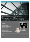
2. User-Level Requirements Specification
A1.
GUI
A. User
Interface
MIDAS
A2.
User Input
B. Patient Image
Database
C.
Processing
Figure 1: Context Model Diagram
2-A. User Interface / Options
The design for the user interface is one of simplicity and ease of use. The various buttons
and their corresponding functions are listed below:
Ø
Ø
Ø
Ø
Ø
Sagital/Axial/Coronal views toggle between the different views of the liver.
Right lobe field displays the right lobe percentage of the whole.
Right lobe volume field displays the right lobe volume in CCs.
Total volume field displays the total volume in CCs.
2-D CT Image is displayed in the left-hand graphics window.
4
Ø 3-D Liver Image with corresponding surgical cutting plane is realized in the righthand graphics window via VTK.
Ø Zoom button allows user to zoom used in conjunction with up and down arrows to
zoom in and out of a certain slice.
Ø Slice button allows user to choose between different slices of data used in tandem
with the up and down arrows to select the previous or next slice.
Ø Overlay button and overlay text box allows user to specify how many layers (slices)
they wish to cut at one time (i.e. the depth of the cut).
Ø Undo button allows user to undo a selected number of slice cuts at one time.
Ø The ‘files/about’ pull down menu will allow file saves, program exits, etc., and
provide information about the program.
Ø Confirm Cut button lets the user decide when they are completely done with a
particular cut.
2-A1. GUI
The graphical user interface is to be created using FLTK. Its function is to allow the user
to interact with the MIDAS program via the touch screen.
2-A2. User Input
The user interacts with the program via the touch screen. The touch screen is what makes
this application so easy to use. Using only a scalpel (same functionality as a mouse) the
user can designate a cutting path for the liver. This allows for steady hand movement and
more accurate cuts.
2-B Patient Image Database
The database consists of the collection of images (e.g. set of CT slices) that are available
for manipulation during the course of this project from Professor Aylward. The
collection of images will be displayed to the user interface via MetaImage for
manipulation.
2-C Processing
Processing will be done via the MIDAS libraries. These libraries were created by
Professor Aylward and are used to process the information designated by the user at the
touch screen. The user can get immediate feedback on the percentages and CCs of each
liver half after a request is sent.
5
6
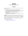
Process Model
1. Start Program
The GUI interface is executed
2.
3.
4.
5.
6.
7.
Image data processed and displayed in GUI
Sends request from touch screen to processing
Request processed by MIDAS libraries
User receives feedback via GUI
Cycle continues
Generated after series of request/processing
interactions. Cutting plane established
according to physician-specified path.
Lobe volume established after each
successive cut (on touch screen)
Image Database Accessed
User request
Processing
Receive response
User makes more requests
System output
7
3. System-Level Requirements Specification
3.1 System-Level Requirement Specification
See Appendix A
3.2 User Interface Requirements
Plan A
•
•
•
•
Selection of Patient Image Database for that particular patient’s liver
Implementing widgets (Confirm Cut, Previous and Next Slice)
Area displaying the 2-D slice will be displayed
Area displaying the 3-D liver will be displayed
Plan B
•
•
•
•
•
•
•
•
•
Implement cutting in the 2-D window by placing alpha blended quads where
the surgeons cut (as opposed to eroding data from the Patient Image database)
Implement an Undo button to erase cuts made
Implement an independent zoom for 2-D CT image
Implement an independent zoom for 3-D CT image
Implement an auto-save function
Implement Print 2-D window
Implement Print 3-D window
Implement Volume calculations and text output to the GUI
Implement Overlay button and the number of overlays
8
BUTTON / DISPLAY BOX
ACTION
A)
File
B)
About
Opens file window to save, open new Patient Image Database,
print 2-D 3-D window, exit
Programmer credits
C)
Sagital
Changes image in 2-D window to the sagital view
D)
Axial
Changes image in 2-D window to the axial view
9
E)
Coronal
Changes image in 2-D window to the coronal view
F)
Total Volume
Displays the total volume of the liver in CCs
G)
Right Lobe Volume (%)
Displays the volume of the right half of the liver in %
H)
Right Lobe Volume (CC)
Displays the volume of the right half of the liver in CCs
I)
3-D Window
Displays the 3-D image of the liver from the Patient Image Database
J)
2-D Window
Displays the 2-D image of the liver from the Patient Image Database
K)
Overlays (On/Off)
Turns the overlays on and off
L)
Number of Slides
Text box for the user to indicate the number of Images to overlay
M)
Restore
Restores 2-D image to state before X cuts were made
(works with [N] below )
N)
Undo
Text box for the user to specify the number of cuts to remove
(works with [M] above )
O)
Plus (Up)
P)
Minus (Down)
Q)
Zoom 2-D
This cycles forward to the next Image or zooms closer depending on
which button has been pressed by the user
(works with [Q], [R], & [S] below)
This cycles backwards to the previous Image or zooms away depending on
which button has been pressed by the user
(works with [Q], [R], & [S] below)
Enables zoom ability in the 2-D image
R)
Zoom 3-D
Enables zoom ability in the 3-D image
S)
Confirm Cut
Enables the calculations to occur and display the new data to the screen
3.3 Non-Functional Requirements
•
•
•
•
3.4
Portability – FLTK can run on Windows or Unix environments
Speed – Quick loading of the Patient Image Database and data updates
Reliability – auto-save function to ensure saved data
Simplicity – User interface must be extremely easy to follow
Goals
The project's emphasis is providing a tool that can be used by clinicians including:
• A 3-D representation of the patient’s slices visualizing a pre-planned surgical
cutting plane
• A very simple user interface that can be operated from a touch screen
• A 2-D view of the patient’s slices from any three positions (Axial, Coronal,
Sagital)
• A tangible way for the surgeons to draw the surgical cut on each slice and have
the software construct the planar surface from each marked slice
10
4. Hardware and Software Resource Requirements
In order for the product to work as expected, there will be recommended hardware
and software requirements. The main hardware requirement will be a powerful cpu and
sufficient ram to handle the intense calculations that must be completed in approximate
real time. The software testing will take place on either a Pentium III 866mhz
Workstation that currently resides in the Graphics lab, or on a Pentium IV 1.4Ghz which
would be acquired in the future by Dr. Stephen Aylward. The desired interface involves
user interaction via a touch screen, one of these units has been obtained, and was declared
insufficient. Dr. Stephen Aylward has since ordered a different touch screen, which
should arrive in the near future (by 2/23/2001). This should not have a significant affect
on the development of the software, but the sooner a decision can be made the better the
GUI can be tapered to the interface mechanism. The utility of a force feedback pen in
place of a touch screen has been explored, but due to the cost may be used as a last
option.
The software requirement that will be enforced is that the computer runs either a
Windows based or Unix based operating system. Most of the software development will
be done using Microsoft Visual C++ under windows, which is available in the labs in the
department. Also the procurement of FLTK, VTK and the MIDAS libraries is essential
in the completion of the final product and has already been obtained.
5. Validation and Verification
5.1) Strategy
In order to test the software, most of the high level, overall
product functionality testing will be done using a black box testing
method. This process will involve using many different CT scans and
known values and comparing these values to the ones that our
program yields. This testing will be done at or near completion of the
product. Some form of white box testing will take place throughout
the entire process. During the programming, since different people
will be programming different components, each of the pieces will
have to be tested to ensure that they not only achieve the assigned
11
task, but also meet the parameter requirements that will allow all the
pieces to work together.
5.2) Test Cases
- Is the UI intuitive and effective? Do the surgeons like what they
see, and is the feedback they receive from the program helpful?
- Does each of the functions do their individual tasks?
- Do the functions use the correct parameters and return types?
- Is the cutting plane reflected correctly in the both the 2-d and 3-d
windows?
- Using data from a previous transplant, compare the volume results
obtained from that procedure to the volumes obtained by using
MIDAS.
- Does the final product meet the specifications set forth at the
beginning of the project?
6. Preliminary Schedule
6.1) Development Items
Major Phases
• Phase I (Pre-Design Phase)
-Meet with client to gain a good working idea of project
-Create a rough preliminary GUI
-Meet with Surgeons and receive their input
-Confirm proposed re-construction of GUI with Client
-Gain sufficient knowledge of FLTK for designing GUI
• Phase II (Design Phase)
12
-Refine GUI
-Present refined GUI to Client
-Make any revisions based on Client’s reaction
• Phase III (Coding/Testing Phase)
-Familiarize ourselves with Doctor Aylward’s C++ Libraries and VTK
-Assign each team member tasks associated with “Plan A” (see 6.1.B)
-Readjust assignments to fit time constraint if needed
-Develop testing and test “Plan A” tasks as they progress
• Phase IV (Implementation Phase)
-Implement “Plan A” tasks as they are finalized
-Implement Touch Screen to be active with GUI
-Test System coordination between GUI and Touch Screen
-Revise System based on any errors found in testing
• Phase V (Plan B {if possible})
-Assign each team member tasks associated with “Plan B” (see 6.1.B)
-Develop testing and test “Plan B” tasks as they progress
-Implement “Plan B” tasks as they are finalized
-Test system with new buttons and make any necessary revisions
Tasks and Dependencies – consists of the functionality of the project implemented
in the buttons of the GUI. There is a list of
implementations for Plan A and B in section 3.2.
Milestones
•
•
•
•
•
•
•
•
•
•
•
•
•
•
Preliminary Report
Project Web I
Presentation of Preliminary GUI
Contract I (with Schedule I)
Contract II (with Schedule II)
Meet with Surgeons for input
Design Specification (with Schedule III)
Obtain a Base User Interface to work with
User Manual I
Prototype
Group Status Report
Implementation of Plan A tasks
Implementation of Touch Screen
Implementation of Plan B tasks {if possible}
13
•
•
•
•
•
•
•
•
•
User Manual II
Implementation Manual
Group Presentation
Project Package
WWW site complete
Team Report
Individual Reports
Final Project
Class Complete
Deliverables
•
•
•
•
•
•
•
•
•
•
•
•
•
Preliminary Report
Contract I
Contract II
Design Specification
User Manual I
Prototype
Group Status Report
User Manual II
Implementation Manual
Project Package
Team Report
Individual Reports
Final Project
6.2) Schedule Diagrams
(following pages)
Can be found at http://www.cs.unc.edu/~gravely/library under the contract II link
Gantt chart
PERT chart
6.3) Risk Analysis and Management
As a group, we are concerned about the implementation of all tasks within the
given time constraint of one semester. We are currently limiting our Plan A to a feasible
amount of work to accomplish so that task assignments to each team member can better
be accomplished. Adjustments could be made as to how much is assigned to each
member later in the semester. Once Plan A is completed, the amount of Plan B that will
be attempted will be assessed then.
Another concern deals with the security in using our finished project. Surgeons
will be using this tool to specify a cutting plain for a liver. If there are errors in our
system, this could mean, at the worst, a loss of a life during the actual surgery. To
counteract this risk, we plan very strenuous testing procedures.
14
15