1
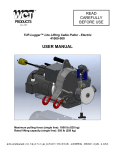
READ CAREFULLY BEFORE USE TUF-Lugger™ Lite 41000-200 and 41000-300 USER MANUAL Models: 41000-200 – Maximum pulling capacity (single line): 2200 lb (1000 kg) 41000-300 – Maximum pulling capacity (single line): 700 lb (350 kg) © 2012 DCD Design & Manufacturing Ltd. - All Rights Reserved English version Summary Introduction – p. 3 1.0 Safety guidelines – p. 3 1.1 Safety messages – p. 3 1.2 Labels – p. 3 1.2.1 Warning label – p. 3 1.2.2 Sound pressure level label – p. 4 1.3 Safety information – p. 4 2.0 Before first use – p. 5 2.1 Upon receiving the winch – p. 5 2.2 Is the engine ready to work? – p. 5 2.2.1 Engine oil – p. 5 2.2.2 Gas (petrol) – p. 5 2.2.3 Engine start-up – p. 5 2.2.4 Capstan drum – p. 6 2.2.5 Spark arrestor – p. 7 3.0 Winch usage – p. 7 3.1 Rope – p. 7 3.1.1 Rope type – p. 7 3.1.2 Rope maintenance – p. 8 3.2 At the end of the rope – p. 8 3.2.1 Recommended knots – p. 8 3.2.2 Recommended hooks – p. 9 3.3 Winch anchor – p. 9 3.3.1 Using the polyester sling (included with the winch) – p. 9 3.3.2 Using the towing ball adapter for tow balls to 2” (50 mm) diameter – p. 10 3.3.3 Using the winch support plate with 2” (50 mm) square tubing – p. 11 3.3.4 Using the tree/pole mount with anchor strap – p. 11 3.3.4.1 With the winch support plate – p. 12 3.3.4.2 With the vertical pull winch support – p. 13 3.4 Oil AlertTM system – p. 14 3.5 Rope installation – p. 14 3.5.1 Rope – p. 14 3.5.2 Pulley – p. 14 3.5.3 Direction – p. 15 3.5.4 On a hill – p. 15 3.6 Pulling a load – p. 15 3.6.1 Wrapping the rope on the capstan drum – p. 15 3.6.2 Winching – p. 16 3.6.2.1 If the rope slips – p. 16 3.6.2.2 To ‘’rock’’ the load – p. 16 3.6.2.3 How to pause while winching – p. 16 3.6.2.4 How to maintain a load without releasing the tension – p. 17 3.6.2.5 How to resume winching – p. 17 3.6.2.6 If you must keep tension on the rope at start-up – p. 17 3.6.2.7 If your rope is too short – p. 17 3.6.3 Stopping the winch – p. 18 4.0 Maintenance – p. 18 4.1 Cleaning – p. 18 4.2 Lubrication – p. 18 4.3 Honda engine – p. 18 4.4 Storage – p. 18 4.5 Spark arrestor – p. 19 5.0 Complementary information – p. 19 5.1 Accessories – p. 19 5.2 Warranty – p. 19 5.3 Serial number localization – p.19 5.4 Exploded view and parts list – p. 20 5.5 Technical data – p. 22 5.6 Noise emissions – p. 22 5.7 Manufacturer – p. 22 2 Introduction DCD Design & Manufacturing Ltd. wishes to thank you for purchasing a TUF-Lugger™ Lite. This manual was written to help you make the best use of your new winch and to use it in the most secure way. READ IT CAREFULLY BEFORE USING THE WINCH. For any problems or questions contact us directly. 1.0 Safety guidelines The TUF-Lugger™ Lite is designed to pull non-rolling objects, usually at a plus or minus 45 degree angle from the horizontal. The use of a pulling device implies serious risks of injuries, property damage or even death. Do not underestimate its potential danger. 1.1 Safety messages Your safety and the safety of others are very important. You will find important safety messages in this manual. Read them carefully. These security messages are warning you of potential injuries to either you or others. Every safety message is preceded by a warning symbol DANGER, WARNING or CAUTION. and one of the following terms: These indicator words mean: You WILL be MORTALLY or SEVERELY INJURED if you do not follow these instructions. You COULD be MORTALLY or SEVERELY INJURED if you do not follow these instructions. You COULD be INJURED if you do not follow these instructions. 1.2 Labels 1.2.1 Warning label The warning label is positioned on the right side of the winch housing. See the meaning of all four icons in the figure 1. 1. Read this instruction manual and Honda engine user’s manual prior to using the winch. 2. Only use low-stretch rope. Minimum diameter: 3/8” (10 mm). Maximum diameter: 5/8” (16 mm). 3. Never place your hands near the drum while the engine is running. 4. Never use the winch for lifting people. 3 1.2.2 Sound pressure level label The sound pressure level label is also positioned on the right side of the winch housing (figure 1). 1. The guaranteed measured sound pressure level (LpA) at operator position is 93 dB. We recommend wearing hearing protection when using your TUF-Lugger™ Lite. 1.3 Safety information DO NOT LET CHILDREN USE THE TUF-LUGGER™ LITE. KEEP CHILDREN AND ANIMALS AWAY FROM THE WORK AREA. NEVER LET SOMEONE WITHOUT TRAINING USE THE TUFLUGGER™ LITE. MAKE SURE THE USER KNOWS ABOUT THE SAFETY AND USAGE PROCEDURES AND HAS READ THIS MANUAL AND THE HONDA ENGINE USER MANUAL. INFORM ALL USERS OF THE SAFETY GUIDELINES AND USAGE PROCEDURES. FAMILIARIZE YOURSELF WITH THE PRODUCT AND THE SAFETY GUIDELINES BEFORE WORKING WITH THE TUF-LUGGER™ LITE. MAKE SURE THAT YOUR CLOTHES ARE NOT GOING TO GET CAUGHT INTO THE TUF-LUGGER™ LITE MOBILE PARTS. THE EXHAUST GAS CONTAINS TOXIC CARBON MONOXIDE. NEVER RUN THE ENGINE IN A CLOSED AREA WITHOUT PROPER VENTILATION. REPLACE ANY SAFETY LABELS THAT ARE DAMAGED, ILLEGIBLE OR MISSING. NEVER PUT YOUR HANDS ON THE CAPSTAN DRUM, NEAR THE ROPE GUIDE OR THE ROPE ENTRY PULLEY WHEN THE ENGINE IS RUNNING. ALWAYS KEEP BYSTANDERS OUTSIDE THE WORKING AREA. NEVER PULL ROLLING OBJECTS THAT MIGHT ROLL OUT OF YOUR CONTROL. 4 THE TUF-LUGGER™ LITE IS NOT INTENDED FOR LIFTING PURPOSES. NEVER USE THE TUF-LUGGER™ LITE TO LIFT PEOPLE. ALWAYS WEAR GLOVES. WE RECOMMEND WEARING HEARING PROTECTION. DO NOT TOUCH THE CAPSTAN DRUM IMMEDIATELY AFTER OPERATION AS IT WILL GET HOT AND BURN BARE SKIN. 2.0 Before first use 2.1 Upon receiving the winch Inspect the box to detect any apparent damage. If there is damage or missing parts, inform the carrier immediately. 2.2 Is the engine ready to work? 2.2.1 Engine oil Fill the Honda engine with a maximum of 0.25 liter of SAE 10W-30 API SJ oil. For special usage or conditions such as extreme weather, refer to page 7 of the Honda engine user manual. Check the oil level on a horizontal surface. The oil level should be up to the edge of the opening. 2.2.2 Gas (petrol) Fill the gas (petrol) tank with UNLEADED PETROL. Do not use oil/gas (petrol) mixture; your TUF-Lugger™ Lite is equipped with a 4-stroke engine. Refer to page 7 of the Honda engine user manual. 2.2.3 Engine start-up Refer to page 3 of the Honda engine user manual for start-up instructions. FIRST USE: LET THE ENGINE RUN FIVE (5) MINUTES AT IDLE BEFORE FIRST PULL. The engine on-off switch is located on the winch housing, to the left of the handle (figure 1). 5 Make sure to pull on the recoil starter in the axis of the rope outlet (figure 1 below). If you pull vertically (figure 2 below) the friction of the rope on the plastic cover might damage the rope and/or the cover. 2.2.4 Capstan drum Your TUF-Lugger™ Lite is equipped with either a 2-1/4” (57 mm) or 3-3/8” (85 mm) diameter capstan drum. If you wish to change the drum, follow these simple installation steps. All bolts require a 5/32” (4 mm) hex wrench, included with your winch manual. 1) Remove the rope guide (figure 1); 2) Remove the bolt located at the end of the drum shaft (figure 2); 3) Remove the original drum from the shaft (figure 3). If necessary, you may push it forward with two screwdrivers. Make sure that the shaft key stays in place. Install bolt and washer; 4) Replace it with the new drum (figure 4); 5) Install the rope guide (included with the new drum) using the two (2) bolts. IMPORTANT: Make sure that the rope guide is not in contact with the capstan drum. 6 2.2.5 Spark arrestor In certain areas, it is forbidden to use a gas (petrol) engine without a spark arrestor. Check local regulations. An optional spark arrestor is available from DCD Design & Manufacturing Ltd. and/or Honda Power Products dealers. Installation: 1) Insert the spark arrestor into the exhaust tube. Make sure the holes are aligned (figure 1); 2) Fasten lightly the metal screw provided with the appropriate screwdriver (figure 2). Refer to page 10 of the Honda engine user manual for the spark arrestor cleaning instructions. DCD Design part number: 42120-000 Honda part number: 350-2M7-801 3.0 Winch usage MOST WINCHING SITUATIONS PRESENT POTENTIAL DANGERS! 3.1 Rope STAY OUT OF THE WINCH LINE’S PATH. 3.1.1 Rope type Use only low stretch rope. We recommend using double-braided polyester rope with a minimum diameter of 3/8” (10 mm). Maximum rope diameter is 5/8” (16 mm). For most situations, we recommend using 1/2” (12 mm) double-braid polyester rope. Please contact us for other rope types suitability. DO NOT USE 3-STRAND POLYPROPYLENE YELLOW ROPE! Polypropylene and polyethylene ropes are dangerous for winching because of their great elasticity and low melt point. Make sure the rope is not damaged and that it offers an adequate resistance to pull the load. 7 STRETCH EQUALS DANGER! A stretched rope can recoil and cause serious burns as the rope leaves your hand. All ropes stretch: a longer one more than a shorter one. The more you pull, the more it stretches. A stretched rope can also move the load in an unpredictable or dangerous way. A stretched rope can recoil and bring your hand towards the winch causing severe injuries. NEVER WRAP THE ROPE AROUND YOUR HAND. ALWAYS WEAR GLOVES. 3.1.2 Rope maintenance VISUALLY INSPECT YOUR ROPE BEFORE EACH USAGE. IF IT SHOWS ANY SIGN OF DETERIORATION (CUT STRANDS, EXCESSIVE ABRASION) REPLACE IT. IF YOUR ROPE IS DIRTY, WASH IT. DIRTY ROPES DETERIORATE FASTER AND CAUSE PREMATURE WEAR ON PARTS WHICH ARE IN CONTACT WITH THE ROPE. 3.2 At the end of the rope 3.2.1 Recommended knots You have to attach the load to the end of the rope. Even if a simple knot can do the job, we recommend the installation of a hook with the bowline knot (figure 1 on the right) because it can be easily undone if you need to change the hook. Moreover, it retains about 70% of the rope’s capacity while most knots will reduce it by more than 50%. Even better, the double bowline knot (figure 2) will keep about 75% of your rope’s capacity. 8 3.2.2 Recommended hooks If you usually pull with a choker chain, use a grab hook (figure 1) or grab hook with latch (figure 2). If you usually pull a sling or a ring, use a safety hook with latch (figure 3) or shackle (figure 4). 3.3 Winch anchor OPTION 1: In most cases, the winch is anchored to a fixed point using the included polyester sling or with optional anchoring devices and the rope end is tied to the object you want to move. The load is moving towards the winch when you pull the rope. OPTION 2: Alternately, the winch can be anchored to the load that needs to be moved and the rope end is tied to a fixed point. The winch and the load are therefore pulled toward the fixed point where the rope end is tied. This method is useful when you need to guide the load while you operate the winch. 3.3.1 Using the polyester sling (included with the winch) Go around the anchor point with the sling. Insert each end of the sling in one of the safety hooks located on the winch (figure 1 below). Position the winch in line with the load. When the winch is under tension, it will try to align itself with the load. The friction of the sling against the anchor point could prevent correct alignment. If that is the case, release the tension on the rope and position the sling on the anchor point so that the tension is equally distributed on both winch anchor hooks. DON’T DO THIS! WHEN YOU ANCHOR THE WINCH, MAKE SURE THAT YOU DO NOT DO A COMPLETE WRAP AROUND THE ANCHOR POINT (FIGURE 2 BELOW). THIS SET-UP WILL PREVENT PROPER ALIGNMENT OF THE WINCH WITH THE LOAD AND WILL PUT UNEVEN TENSION ON THE WINCH ANCHOR HOOKS. 9 AVOID INSTALLING THE SLING ON SHARP EDGES THAT MIGHT DAMAGE IT. WHETHER YOU ARE USING A POST, A TREE OR A STUMP, ALWAYS INSTALL THE SLING NEAR THE ANCHOR’S BASE. USING A STUMP AS AN ANCHOR POINT MEANS PAYING SPECIAL ATTENTION IN ORDER TO PREVENT THE SLING FROM SLIPPING OVER IT. MAKE SURE THE ANCHOR POINT IS STRONG ENOUGH TO RESIST THE PULL WITHOUT BREAKING OR BEING DAMAGED. 3.3.2 Using the towing ball adapter (42200-030) for tow balls up to 2” (50 mm) diameter 1) Figure 1: Push the safety hooks in the rectangular openings of the hitch plate. The rubber plate must be under the winch; 2) Figure 2: Start the winch engine; 3) Figure 3: Slide the plate on the ball hitch and pull the winch forward; 4) Figure 4: Wrap the rope around the drum and start winching. The winch will align itself automatically with the load. NOTE: Do not leave the winch on the hitch with the engine running; the resting position will cause the Oil AlertTM device to turn the Honda engine off (see section 3.4). USE THE HITCH PLATE ONLY WITH CATEGORY II BALL HITCH (3300 LB (1500 KG)) OR HIGHER. MAKE SURE THE ANCHORING VEHICLE’S HAND BRAKE IS ON AND WORKING PROPERLY. POSITION BLOCKS BEHIND THE WHEELS TO PREVENT ROLL BACK. 10 3.3.3 Using the winch support plate (42200-010) with 2” (50 mm) square tubing (42200-020) 1) Figure 1, no. 1: Slide the square tubing (42200-020) into the vehicle’s receiver and secure it with both the hitch pin and the ‘’R’’ pin; 2) Figure 1, no. 2: Slide the winch support plate (42200-010) onto the square tubing and secure it with both the hitch pin and the ‘’R’’ pin; Note: Its lateral movement can be adjusted by positioning the bolts into the square holes; 3) Figure 2: Attach the winch anchor hooks to the eye bolts; 4) Figure 2: Wrap the rope around the drum and start winching. The winch will align itself automatically with the load. IF YOU NEED TO PULL DOWNWARD, YOU WILL NEED TO INSTALL EITHER A PULLEY OR A ROLLER TO PREVENT DAMAGE TO THE WINCH SUPPORT PLATE. MAKE SURE THE ANCHORING VEHICLE’S HAND BRAKE IS ON AND WORKING PROPERLY. POSITION BLOCKS BEHIND THE WHEELS TO PREVENT ROLL BACK. 3.3.4 Using the pole mount with anchor strap (42200-040) The pole mount is intended to use with either the winch support plate (42200-010) or the vertical pull winch support (42200-050). Therefore, you must first install the pole mount. To do this, follow these steps: 1) Figure 1: Place the pole mount at the base of pole or tree. Insert the sling’s hook into the anchor point on the left; then feed the sling’s end through the ratchet system; 2) Figure 2: Slide the whole set-up upward to the desired height and remove the supplied wrench; 11 3) Figure 3: Tighten the sling with the wrench while making sure the rubber pads are properly positioned. The pads should offer maximum contact surface with the tree or pole. 3.3.4.1 With the winch support plate (42200-010) After the installation of the tree/pole mount (section 3.3.4), follow these steps: 1) Figure 1: Insert the winch support plate onto the square tubing of the pole mount (42200040) and fasten it down with the hitch pin and ‘’R’’ pin; 2) Figure 2: Attach the winch anchor hooks to the eye bolts of the winch support plate; 3) Figure 3: Wrap the rope around the drum and start winching. The winch will align itself automatically with the load. 12 IF YOU NEED TO PULL DOWNWARD, YOU WILL NEED TO INSTALL EITHER A PULLEY OR A ROLLER TO PREVENT DAMAGE TO THE WINCH SUPPORT PLATE. AFTER PULLING FOR A FEW SECONDS WITH THE TREE/POLE MOUNT, RELEASE THE TENSION OFF THE TUF-LUGGER™ LITE. CHECK THE SOLIDITY OF THE INSTALLATION AND TIGHTEN THE SLING AGAIN. 3.3.4.2 With the vertical pull winch support (42200-050) After the installation of the pole mount (section 3.3.4), follow these steps: 1) Figure 1: Insert the vertical pull winch support onto the square tubing of the tree/pole mount (42200-040), align the holes and insert the pulley; 2) Figure 2: Tighten the nut with your fingers until it touches the support. Then reinforce it with the ‘’R’’ pin; 3) Figure 3: Attach the winch anchor hooks to the eye bolts of the vertical pull winch support; 4) Figure 4: Wrap the rope around the drum and align the vertical support pulley with the rope axe and start to pull; THE TUF-LUGGER™ LITE IS NOT INTENDED FOR LIFTING PURPOSES. 13 IMPORTANT: DON’T THE WINCH WITH THE ROPE (FIGURE AND WILL REDUCE LIFTING CAPACITY. 1 BELOW). IN THIS CASE, THE ROPE USED. GO OVER THE ROPE ENTRY PULLEY OF 2 BELOW) AS IT WILL CREATE FRICTION GO UNDER THE ROPE ENTRY PULLEY (FIGURE ENTRY PULLEY OF THE WINCH WILL NOT BE IMPORTANT: AFTER PULLING FOR A FEW SECONDS, RELEASE THE TENSION AND CHECK THE SOLIDITY OF THE INSTALLATION AND TIGHTEN THE SLING OF THE TREE/POLE MOUNT AGAIN. 3.4 Oil AlertTM system The GX-50 Honda engine is equipped with an Oil AlertTM system that automatically turns off the ignition when the oil level goes below a safe level. The Oil AlertTM system also turns off the ignition when the winch is operating at an angle greater than 20 degrees (± 4 degrees). Make sure that your set-up keeps the winch at a relatively horizontal level while winching and idling. 3.5 Rope installation USING COMMON SENSE WHILE INSTALLING THE ROPE IS THE KEY TO SECURE WINCH USAGE. The great variety of situations encountered when winching prevents us from providing specific instructions; however you need to consider the following points: 3.5.1 Rope Use a low stretch rope, in good condition, with a minimum diameter of 3/8” (10 mm) and a maximum diameter of 5/8” (16 mm), with good knots. We strongly suggest the bowline knot (see section 3.2.1). Use pulleys to redirect the rope and to multiply the pulling capacity when the load is near or over the pulling capacity of the winch. 3.5.2 Pulley Using a pulley at some distance in front of the winch offers many advantages: Pulling angle ‘lifts’ the load and reduces friction; The winch is maintained at a relatively horizontal position; Winch and operator are away from the load’s path. 14 3.5.3 Direction Install the rope in such a way that it does not rub against other objects. Try to set-up the rope so that the front of the load is slightly lifted. Do not pull downwards or through an obstruction. Generally, if the rope touches the ground while pulling, your installation is incorrect. 3.5.4 On a hill DO NOT PULL A LOAD DIRECTLY TOWARD THE WINCH IN A DOWNWARD SLOPE SINCE IT COULD SLIDE WITHOUT YOU BEING ABLE TO STOP IT. IN THAT SITUATION, USE A PULLEY AT THE BOTTOM OF THE HILL AND POSITION THE WINCH OUTSIDE OF THE LOAD’S PATH. 3.6 Pulling a load CHECK WINCH POSITION, ROPE CONDITION, SOLIDITY OF THE ANCHOR POINT, KNOTS, CARABINERS OR SHACKLES IN ORDER TO PREVENT INJURIES OR MATERIAL DAMAGE. 3.6.1 Wrapping the rope on the capstan drum NEVER PUT YOUR HANDS ON THE CAPSTAN DRUM, THE ROPE GUIDE OR THE ROPE ENTRY PULLEY WHEN THE ENGINE IS RUNNING. 1) Start the engine and let it idle for 30 seconds to warm-up; 2) Run the rope OVER THE ROPE KEEPER and the rope entry pulley and under the drum (figure 1, no. 1); 3) Wrap the rope around the drum (3 or 4 turns) (figure 1, no. 2); 4) Bring the rope behind the rope hook (figure 1, no. 3); 5) Stand about 3’ (1 m) winch and pull gently and horizontally on the rope to get the slack until you feel the tension rising on the rope; 6) Look at your set-up to make sure that the winch anchor and the rope entry pulley are aligned with the rope; 7) Check that the rope does not rub against objects along the path; 8) Pull the throttle up and start winching. 15 3.6.2 Winching While winching, position yourself away from the winch in order to see both the winch and the load. Pull HORIZONTALLY on the rope. The tension you exert on the rope will keep the winch level. Do not operate with the winch tilted or the Oil Alert™ will kick in. DO NOT WRAP THE ROPE AROUND YOUR HANDS OR YOUR BODY! ALSO BEWARE OF THE ROPE ACCUMULATING IN FRONT OF YOU; MAKE SURE YOUR FEET DO NOT GET TANGLED IN IT. CAREFULLY WATCH THE CAPSTAN DRUM DURING THE OPERATION AND MAKE SURE THAT THE ROPE DOES NOT CROSS OVER ON IT. IF IT HAPPENS, RELEASE THE TENSION ON THE ROPE AND STOP THE ENGINE WHILE UNDOING THE CROSS OVER. 3.6.2.1 If the rope slips If the rope slips on the drum while winching, add a fourth wrap of rope on the drum. When the winch reaches its maximum capacity, the engine stalls. You then have to redo your set-up (add pulleys) or ‘’rock’’ the load (see section 3.6.2.2). 3.6.2.2 To ''rock'' the load Pull the rope until the engine comes close to stalling and release the tension. Pull again on the rope to put tension and repeat as needed. BE CAREFUL WITH THIS METHOD SINCE IT GENERATES HEAT AND CAN WEAR THE ROPE QUICKLY. IF THE WINCH IS PULLING THE ROPE BUT THE LOAD DOES NOT MOVE (OFTEN THE CASE WHEN USING A VERY LONG ROPE), IT’S BECAUSE YOUR ROPE IS STRETCHING AND COULD REACH THE BREAKING POINT AND RECOIL TOWARDS YOU. SLOWLY RELEASE THE TENSION ON THE ROPE BUT BEWARE OF THE ACCUMULATED TENSION. YOU COULD GET BURNED FROM THE ROPE EXITING YOUR HANDS QUICKLY OR BE PULLED TOWARDS THE WINCH. 3.6.2.3 How to pause while winching SLOWLY release the tension on the rope and let it slip on the capstan drum. DO NOT LET THE ROPE SLIP FOR MORE THAN A FEW SECONDS ON THE DRUM WHILE IN TENSION – THE HEAT CREATED BY THE FRICTION COULD MELT OR DAMAGE THE ROPE. 16 3.6.2.4 How to maintain a load without releasing the tension You may maintain tension on the end of the rope either by holding it or attaching it: 1) Shut the engine off; 2) Wrap the rope twice around the rope hook to relieve tension from your hands (figure 1); 3) Tie two half-knots around the rope hook (figure 2). 3.6.2.5 How to resume winching You must release some tension before restarting the winch engine. First, untie the two halfknots. Let go of some of the rope to release some tension. While holding the rope with one hand, start the engine by pulling on the crank and pull the throttle up. You can now resume winching. 3.6.2.6 If you must keep tension on the rope at start-up You can install a rope grab device or a Prussik knot attached to your anchor point in order to keep tension on the rope. 3.6.2.7 If your rope is too short If your rope is too short, you will have to link two ropes together: 1) Figure 1, no. 1: Using the bowline knot (section 3.2.1), link your two ropes together; 2) Figure 1, no. 2: IMPORTANT: Leave about 3’ (1 m) of rope tailing out of the knot on the rope holding the load. You will need it to resume winching after undoing the knots; 3) Figure 2: Stop the winch BEFORE the knot reaches the rope entry pulley of the winch since it CANNOT GO THROUGH it; 4) Release tension off the rope. If necessary, attach the load to a fixed object; 5) Undo the knots and use the remaining length (3’ or 1 m) to wrap around the capstan drum and start winching again. 17 3.6.3 Stopping the winch 1) Release tension gradually to lower the winch gently to the ground; 2) Bring throttle down to idle; 3) Turn ignition switch off. 4.0 Maintenance 4.1 Cleaning Once your job is done, you should clean and dry your winch. INSPECT THE WINCH, HOOKS, ROPE, KNOTS AND POLYESTER SLING TO DETECT ANY DAMAGE OR SIGNS OF WEAR. Periodically, remove the capstan drum (section 2.2.4) and clean around the shaft (figure 1). Accumulated debris can damage the shaft seal. Apply oil to prevent corrosion. 4.2 Lubrication The rope entry pulley (figure 1, no 1) must turn freely. Lubricate it regularly with light oil. Dirt and grime lodged between the pulley and the shaft may prevent it from turning freely. If required, disassemble it to clean the shaft. Use an 8 mm hex key. The gearbox is lubricated at the factory and should not require additional lubrication or maintenance. If there is appearance of a leak, check oil level by placing the winch on a level surface and remove the oil plug (figure 1, no 2). Use an 8 mm hex key. Lean it toward you; some oil should leak out of the hole. If needed, you can add type SAE80W90EP gear box oil. 4.3 Honda engine Maintain the engine according to the instructions found in the Honda engine user manual provided. 4.4 Storage Always store your TUF-Lugger™ Lite seated on its protection plate. Refer to the Honda engine user manual for engine storage instructions. 18 4.5 Spark arrestor If your TUF-Lugger™ Lite is equipped with the optional spark arrestor (42120-000, sold separately), you must clean it every hundred (100) hours to keep it running properly. Refer to the Honda engine user manual for cleaning instructions. 5.0 Complementary information 5.1 Accessories A complete line of accessories is available. You will find the list on our website at www.dcddesign.com. 5.2 Warranty DCD Design & Manufacturing Ltd. products are warranted against defects in materials and workmanship while owned by the ''original purchaser'' as defined below. The ''original purchaser'' is defined as the party or entity which purchases the winch and/or accessories from an authorized DCD Design & Manufacturing Ltd. retailer as shown by the original sales receipt. The warranty ownership is transferable, provided the end-user has a copy of the original purchaser’s invoice. This warranty does not apply to ''wear parts'' defined as being in contact with the rope while winching. The TUF-Lugger™ Lite is covered as follows: Winch components: o Private use: Five (5) year warranty (service by DCD Design & Manufacturing Ltd. and/or its retailers); o Commercial use: One (1) year warranty (service by DCD Design & Manufacturing Ltd. and/or its retailers); Engine: The Honda engine is warranted by Honda Motor Corporation and the duration varies according to country and usage. All Honda service centers can repair the winch engine under warranty. Retain your proof of purchase (invoice with serial number). It will be used to establish the beginning of the warranty period. DCD Design & Manufacturing Ltd. will replace or repair, at its option, any defective product. All other TUF-LuggerTM Lite accessories are covered by a complete one (1) year warranty. Please refer to the DCD Design & Manufacturing Ltd. complete warranty on www.dcddesign.com if you have any questions. 5.3 Serial number localization The winch serial number is indicated on the safety warning label located on the right side of the winch housing and is also engraved on the cover of the winch, to the left of the capstan drum 19 5.4 Exploded view and parts list 20 ITEM NO. PART NUMBER DESCRIPTION QTY 1 4 2 2 6 1 1 1 1 1 2 3 4 5 6 7 8 9 31-0010 35-0004 10-0098 42430-020 31-0024 10-0099 44-0019 10-0094 44-0027 10 70-0023 11 12 13 14 35-0006 39-0007 31-0019 33-0005 15 44-0028 16 17 18 19 20 21 22 23 24 25 44-0023 10-0103 10-0101 10-0119 10-0100 43-0013 31-0025 10-0096 10-0102 10-0001 HCS 1/2-13 X 6 - GR5 - ZN FLAT WASHER 1/2 - ZN BUSHING FOR SAFETY HOOK SAFETY HOOK 3/4 TON BHCS 1/4-20 X 1 - SS ALUMINIUM ROPE EXIT HOOK VINYL GRIP WINCH HANDLE ROPE INSTALLATION LABEL TUF-LUGGER LITE ON/OFF SWITCH WITH SUPPORT PLATE FOR GXH-50 ENGINE FLAT WASHER 1/4 - ZN METAL SCREW NO. 10 X 1/2 (PAN HEAD. SQ. DR.) HCS 3/8-24 X 1 GR5 - ZN NYLON LOCKNUT 1/2-13 ZN UNIVERSAL SERIAL NUMBER & WARNING LABEL DCD DESIGN DECIBEL WARNING 93 dB LABEL ROPE KEEPER ROPE ENTRY PULLEY SHOULDER BOLT 5/8 X 1-1/2 - ZN ROPE GUIDE FOR CAPSTAN DRUM 2-1/4” SHAFT KEY FOR CAPSTAN DRUMS 2-1/4” & 3-3/8” BHCS 1/4-20 X 3/4 - SS CAPSTAN DRUM 57 MM DRUM RETAINING WASHER CAPSTAN DRUM 85 MM 26 31-0025 BHCS 1/4-20 X 3/4 - SS 2 27 10-0106 ROPE GUIDE FOR CAPSTAN DRUM 3-3/8” 1 1 2 1 1 1 1 1 1 1 1 1 1 6 1 1 1 21 5.5 Technical data 41000-200 and 41000-300: Engine: 4-stroke Honda GXH-50 cc Gear box: Aluminum alloy Unit weight (dry): 35 lb (16 kg) Dimensions (overall): 13'' wide x 14'' high x 15'' deep (33 cm x 36 cm x 38 cm) Rope: Low stretch double braided polyester (not included) - Unlimited rope length o Minimum diameter: 3/8'' (10 mm) o Maximum diameter: 5/8'' (16 mm) o Recommended: 1/2'' (12 - 13 mm) 41000-200: Gear ratio: 110:1 Pulling force (according to drum diameter): o Installed: 2-1/4'' (57 mm) drum: 2200 lb (1000 kg) o Optional: 3-3/8'' (85 mm) drum: 1400 lb (635 kg) Speed (according to drum diameter): o Installed: 2-1/4'' (57 mm) drum: 40'/min (12 m/min) o Optional: 3-3/8'' (85 mm) drum: 60'/min (18 m/min) 41000-300: Gear ratio: 53:1 Pulling force (according to drum diameter): o Installed: 3-3/8'' (85 mm) drum: 700 lb (350 kg) o Optional: 2-1/4'' (57 mm) drum: 1100 lb (500 kg) Speed (according to drum diameter): o Installed: 3-3/8'' (85 mm) drum: 120'/min (36 m/min) o Optional: 2-1/4'' (57 mm) drum: 80'/min (24 m/min) 5.6 Noise emissions Here are the noise emissions of the TUF-Lugger™ Lite: Sound pressure level at operator position – L P A (measured) o Engine idling: 73 dBA o Full throttle: 89 dBA 5.7 Manufacturer The TUF-Lugger™ Lite is manufactured for: DCD Design & Manufacturing Ltd. 180-6620 McMillan Way Richmond, BC, V6W 1J7 CANADA Phone: +1 604-232-4445 Toll free (Canada & USA): 1-888-794-8357 Fax: +1 604-232-4446 Email: [email protected] Web site: www.dcddesign.com 22