1
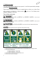
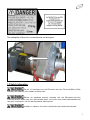
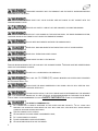
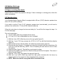
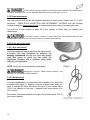
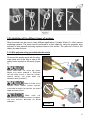
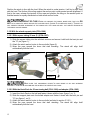
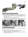
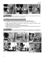
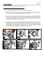
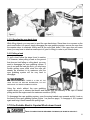
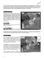
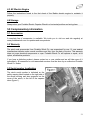
READ
CAREFULLY
BEFORE USE
Portable Winch Co.
PORTABLE ELECTRIC CAPSTAN WINCH
PCT1800-50Hz-P
USER MANUAL
Model: PCT1800-50Hz-P
Maximum pulling capacity (single line) : 820 kg (1800 lb)
Rated pulling force (single line) : 455 kg (1000 lb)
Lifting capacity : 250 kg (550 lb)
© Portable Winch Co., November 2011
All Rights reserved
English version
Summary
Introduction – p. 3
1.0 Safety guidelines – p. 3
1.1 Safety messages – p. 4
1.2 Labels – p. 4
1.3 Safety information – p. 5
2.0 Before first use – p. 7
2.1 Upon receiving the winch – p. 7
2.2 Capstan drum – p. 7
3.0 Winch usage – p. 9
3.1 Working cycle – p. 9
3.2 Rope – p. 9
3.2.1 Rope type – p. 9
3.2.2 Rope maintenance – p. 10
3.2.3 At the end of the rope – p. 10
3.2.3.1 Eye splice end – p. 10
3.2.3.2 Bowline knot – p. 10
3.3 Installation of the different types of anchors – p. 11
3.3.1 With polyester sling (provided with the winch) – p. 11
3.3.2 With the winch support plate – p. 12
3.3.2.1 With square tubing 50 mm (2") – p. 12
3.3.2.2 With the Heck-Pack for 50 mm towing ball and adaptor – p. 12
3.3.3 With the tree/pole mount with anchor strap (PCA-1263) – p. 13
3.3.3.1 With the winch support plate – p. 13
3.3.3.2 With the vertical pull winch support – p. 14
3.4 Wrapping the rope on the capstan drum – p. 15
3.5 Moving a load – p. 16
3.5.1 Lifting a load – p. 16
3.5.1.1 Lifting charts – p. 17
3.5.1.2 Sending the rope back down – p. 19
3.6.1 Pulling a load – p. 19
3.7 If the Portable Electric Capstan Winch doesn’t work – p. 19
4.0 Maintenance – p. 20
4.1 Cleaning – p. 20
4.2 Lubrication – p. 20
4.3 AC Electric Engine – p. 21
4.4 Storage – p. 21
5.0 Complementary information – p. 21
5.1 Accessories – p. 21
5.2 Warranty – p. 21
5.3 Serial number localization – p. 21
5.4 Technical data – p. 22
5.5 Periodical tests – p. 22
5.6 CE Declaration of conformity – p. 23
5.7 Exploded view and parts list – p. 24
5.8 Electrical plans – p. 27
5.9 Manufacturer – p. 28
Annexe I. Examining the rope – p. 29
2
Introduction
Portable Winch Co. wishes to thank you for purchasing a PCT-1800 Portable Electric Capstan
Winch. This manual was written to help you make the best use of your new electric winch and to
use it in the most secure way. Read it carefully before using the electric winch. For any
problems or questions please refer to an authorized Portable Winch Co. dealer or contact us
directly.
NOTE TO THE USER: PLEASE REFER TO THIS MANUAL AND THE BALDOR ELECTRIC
MOTOR LEAFLET FOR GENERAL INFORMATION.
1.0 Safety guidelines
The PCT-1800 Portable Electric Capstan Winch is designed to pull non-rolling objects, usually
at a plus or minus 45 degree angle from the horizontal. It can also be used to lift objects. It is
equipped with a rope grabbing system that can hold a load in position and will restart under
tension.
A
RAPIDLY LOWERING LOAD WILL NOT BE RESTRAINED BY THE ROPE BLOCKING
SYSTEM.
THE
USE OF A PULLING DEVICE IMPLIES SERIOUS INJURY OR EVEN DEATH OR
PROPERTY DAMAGE. DO NOT UNDER-ESTIMATE THE POTENTIAL DANGER.
THE MANUFACTURER IS NOT RESPONSIBLE FOR DAMAGE CAUSED BY THE FAILURE
OF THE REQUIREMENTS CONTAINED IN THIS DOCUMENT AND THE FAILURE TO FOLLOW SAFETY
REGULATIONS.
In particular, the USER has the obligation to verify :
a) If the electrical plug is equipped with a ground compatible with the connector;
b) If the electrical system is adequate;
c) The execution of safety measures for the prevention of falls.
NEVER SURPASS THE RATED PULLING FORCE :
PULLING : 455 KG (1000 LB) SINGLE LINE.
LIFTING : 250 KG (555 LB) SINGLE LINE.
DO NOT USE THE WINCH WITHOUT USING THE ROPE BLOCKING SYSTEM.
THE WINCH MUST NOT RECEIVE ANY BACKLASHES.
NEVER USE THE WINCH WITHOUT PROPER TRAINING AND SUPERVISION.
REMEMBER THAT THE FIRST CAUSE OF AN ACCIDENT IS HUMAN ERROR. BE SURE THAT ALL
OPERATORS HAVE THE NECESSARY TRAINING.
3
1.1 Safety messages
Your safety and the safety of others are very important. You will find important safety messages
in this manual. Read them carefully.
These security messages are warning you of potential injuries to either you or others. Every
safety message is preceded by a warning symbol
DANGER, WARNING or CAUTION.
and one of the following terms:
These indicator words mean:
YOU WILL
FOLLOW THESE INSTRUCTIONS.
BE
YOU COULD
FOLLOW THESE INSTRUCTIONS.
MORTALLY
BE
OR
MORTALLY
SEVERELY INJURED
OR
SEVERELY INJURED
IF YOU DO NOT
IF YOU DO NOT
YOU COULD BE INJURED IF YOU DO NOT FOLLOW THESE INSTRUCTIONS.
1.2 Labels
The warning label is positioned on the right side of the winch housing.
1
2
3
4
1) Read carefully this manual and the Baldor Electric motor pamphlet prior to using the winch.
2) Only use low stretch rope.
a. Minimum diameter : 12 mm (1/2")
b. Maximum diameter : 13 mm (1/2")
3) Never place your hands near the drum when in use.
4) Never use the winch to lift people.
4
The nameplate of the motor is riveted directly on the engine.
1.3 Safety infomation
DO NOT LET CHILDREN USE THE PORTABLE ELECTRIC CAPSTAN WINCH. KEEP
CHILDREN AND ANIMALS AWAY FROM THE WORK AREA.
NEVER
CAPSTAN WINCH. MAKE SURE
LET SOMEONE WITHOUT TRAINING USE THE PORTABLE ELECTRIC
THE USER KNOWS ABOUT THE SAFETY AND USAGE PROCEDURES AND
HAS READ THIS MANUAL AND THE BALDOR ENGINE USER MANUAL.
INFORM ALL USERS OF THE SAFETY GUIDELINES AND USAGE PROCEDURES.
5
FAMILIARIZE YOURSELF WITH THE PRODUCT AND THE SAFETY GUIDELINES BEFORE
WORKING WITH THE WINCH.
MAKE
SURE THAT YOUR CLOTHES ARE NOT GOING TO GET CAUGHT INTO THE
WINCHES MOBILE PARTS.
REPLACE ANY SAFETY LABELS THAT ARE DAMAGED, ILLEGIBLE OR MISSING.
NEVER PUT YOUR HANDS
ON THE CAPSTAN DRUM, THE ROPE GRABBING SYSTEM,
THE ROPE GUIDE OR THE FRONT PULLEY WHEN THE ENGINE IS RUNNING.
ALWAYS KEEP BYSTANDERS OUTSIDE THE WORKING AREA.
NEVER PULL ROLLING OBJECTS THAT MIGHT ROLL OUT OF YOUR CONTROL.
NEVER PULL FIXED OR BLOCKED LOADS.
AVOID SHORT PULSES TO THE MOTOR.
ALWAYS BEGIN MOVEMENT OF THE LOAD WITH THE SLOWEST SPEED. THE ROPE MUST BE UNDERTENSION
WHEN THE LOAD BEGINS TO MOVE.
DO NOT PULL A SUSPENDED LOAD SIDEWAYS.
ONLY USE THE
BY PORTABLE W INCH CO.
12-13 MM (1/2")
DOUBLE BRAIDED POLYESTER ROPE PROVIDED
ALWAYS USE THE WINCH HORIZONTALLY BY USING A PULLEY OR A VERTICAL PULL
SUPPORT TO REDIRECT THE ROPE VERTICALLY.
FOR ANY INSTALLATION, THE TOTAL RESISTANCE IS DETERMINED BY THE WEAKEST
LINK. IT IS THEREFORE IMPORTANT TO USE THE RIGHT ACCESSORIES BASED ON THE WORK TO BE DONE.
FOR LIFTING IT IS RECOMMENDED TO HAVE A SAFETY FACTOR OF 10:1 FOR ALL ACCESSORIES.
IT IS STRICTLY FORBIDDEN TO :
LIFT
LOADS WITH A WEIGHT SUPERIOR TO THE RATED PULLING CAPACITY; TO LIFT LOADS THAT
PREVENT THE OPERATOR FROM SEEING OR THAT MAY COME INTO COLLISION WITH OTHER MOVING
LOADS OR ADJACENT FIXED STRUCTURES;
USE THE WINCH TO LIFT PEOPLE;
ALLOW PEOPLE TO PASS UNDER A SUSPENDED LOAD;
LIFT LOADS POORLY ALIGNED;
LEAVE SUSPENDED LOADS UNATTENDED;
ALLOW OTHER PEOPLE TO USE THE WINCH.
6
2.0 Before first use
2.1 Upon receiving the winch
Inspect the box to detect any apparent damage. If there is damage or missing parts, inform the
carrier immediately.
2.2 Capstan drum
Your Portable Electric Capstan Winch is equipped with a 85 mm (3-3/8") diameter capstan drum
and a 127 mm (4-5/8") safety lip.
If you wish to use the 57 mm (2-1/4") diameter capstan drum (non-included), you will need to
purchase it as well as the 117 mm (4-5/8") diameter safety lip.
Follow the instructions to change the drum and safety lip. You will find the images for steps 1 to
9 on the next page.
The tools required are :
A 4 mm (5/32") Allen key included with the winch;
A 11 mm (7/16") key or adjustable key (non- included).
1) With the 4 mm (5/32") Allen key remove the rope guide (figure 2);
2) With the 11 mm (7/16") key unscrew the 1/4"-20 x 2-1/4" hex bolt that holds the safety lip
(figure 3);
3) Remove the hex bolt, the flat washer, the safety lip and the spacer (figure 4);
4) Remove the drum (figure 5). If needed, you may push it forward with two screwdrivers. Be
sure not to lose the shaft key; (NOTE : Prior to installing the new drum be sure to clean
the surface).
5) Insert the drum (figure 6). The shaft key must remain in place;
6) Insert the flat washer in the hex bolt, then the safety lip and then the spacer. Then srew it
all into the axel (figure 7);
7) With the 11 mm (7/16") key tighten the hex bolt (figure 8);
8) With the 4 mm (5/32") Allen key install the rope guide (included with the drum) by
tightening the two (2) screws into their designated holes. (figure 9).
9) NOTE : Make sure that the rope guide doesn’t touch the drum.
7
8
3.0 Winch usage
MOST WINCHING SITUATIONS PRESENT POTENTIAL DANGERS!
The winch must be plugged into grounded plug. The use of an extension cord can cause a loss
of power at full capacity. As listed on the product label, make sure the voltage and current type
are respected. Units 115V-60hz require 20 amps while the units 220V-50hz require 10 amps.
IMPORTANT NOTE: You must release the tension to the rope before restarting to pull. Do
not start under tension.
3.1 Working cycle
This winch is designed for intermittent use. The engine manufacturer recommends an engine
duty cycle of 25%. So, to get a maximum lifetime out of the engine, it should only be used for
fifteen (15) minutes period every hour. This data varies depending on the loads pulled or lifted.
Light loads can be lifted or pulled continuously without affecting the life of the engine.
3.2 Rope
3.2.1 Rope type
Only use a low stretch double-braided polyester rope with a diameter of 12-13 mm (1/2") and a
minimum breaking strength of 3150 kg (6945 lb) with this winch. Please contact us for other rope
types suitability.
DO NOT USE 3-STRAND POLYPROPYLENE YELLOW ROPE!
Polypropylene and polyethylene ropes are dangerous for winching because of their great
elasticity and low melt point.
Make sure the rope is not damaged and that it offers an adequate resistance to pull the
load.
STRETCH EQUALS DANGER!
A stretched rope can recoil and bring your hand or body towards the winch causing severe
injuries.
A stretched rope can also move the load in an unpredictable or dangerous way.
All ropes stretch: a longer one more than a shorter one. The more you pull, the more it stretches.
Be careful when letting go of a rope under tension. A stretched rope can recoil and cause serious
burns as the rope leaves your hand.
ALWAYS WEAR GLOVES.
ALWAYS STAND TO THE SIDE OF THE WINCHING LINE.
9
DO NOT WRAP THE ROPE AROUND YOUR HANDS OR YOUR BODY! ALSO BEWARE OF
THE ROPE ACCUMULATION ON THE GROUND, BE SURE TO KEEP YOUR FEET OUT OF IT.
3.2.2 Rope maintenance
The rope and its ends should be inspected regularly to detect wear. Please refer to CI 2001
Document - FIBER ROPE INSPECTION AND RETIREMENT CRITERIA from the Cordage
Institute available at www.ropecord.com for the procedure and criteria of scrapping the rope.
You will find a chart located at page 29 of this manual to better help you register your
observations.
IF THE ROPE IS DIRTY, WASH IT. A DIRTY ROPE WILL GET DAMAGED QUICKLY AND
CAUSE PREMATURE WEAR TO THE PARTS IN WHICH IT COMES INTO CONTACT.
3.2.3 At the end of the rope
3.2.3.1 Eye spliced end
You must attach the load to the end of the rope. Even if
a bowline knot may sometimes be sufficient, we
strongly recommend the use of a rope with spliced
ends (see figure) to which you can install the
appropriate hardware with a sufficient safety factor
rating for your application.
NOTE: Verify your local regulations in this matter.
IMPORTANT FACTOR : MOST
CAPACITY OF THE ROPE BY 50% OR MORE.
KNOTS REDUCE THE
3.2.3.2 Bowline knot
For pulling applications, we recommend the installation of a hook with
a bowline knot (figure 1), because it can be undone easily when you
need to change the hook. Moreover, this type of knot retains about
70% of the capacity of the rope – whereas most knots reduce it by
50% or more.
Even better, the double bowline knot (figure 2) will retain about 75% of
your rope’s capacity.
10
3.3 Installation of the different types of anchors
Since the winch can be used in many different applications, Portable Winch Co. offers various
anchoring systems. The winch can be anchored to a fixed object by using the polyester sling
included or with optional anchoring systems listed in this section. The rope end is tied to the
object you want to move.
3.3.1 With polyester sling (provided with the winch)
Go around the anchor point with the sling.
Insert each end of the sling in one of the
safety hooks located on the winch (figure
1).
AVOID
INSTALLING THE SLING ON SHARP
EDGES THAT MIGHT DAMAGE IT. W HETHER
YOU ARE USING A POST, A TREE OR A STUMP,
ALWAYS INSTALL THE SLING NEAR THE
ANCHOR’S BASE (FIGURE 1).
FIGURE 1
USING A STUMP AS AN
ANCHOR POINT MEANS PAYING SPECIAL
ATTENTION IN ORDER TO PREVENT THE SLING
FROM SLIPPING OVER IT.
MAKE SURE THE
ANCHOR POINT IS STRONG ENOUGH TO RESIST
THE PULL WITHOUT BREAKING OR BEING
DAMAGED.
FIGURE 2
11
Position the winch in line with the load. When the winch is under tension, it will try to align itself
with the load. The friction of the sling against the anchor point could prevent correct alignment. If
that is the case, release the tension on the rope and position the sling on the anchor point so
that the tension is equally distributed on both winch anchor hooks.
DON’T DO THIS! W HEN YOU ANCHOR THE WINCH, MAKE SURE THAT YOU DO
DO A COMPLETE WRAP AROUND THE ANCHOR POINT (FIGURE 2 ON PREVIOUS PAGE). THIS SET-UP
WILL PREVENT PROPER ALIGNMENT OF THE WINCH WITH THE LOAD AND WILL PUT UNEVEN TENSION ON
THE WINCH ANCHOR HOOKS.
NOT
3.3.2 With the winch support plate (PCA-1268)
3.3.2.1 With square tubing 50 mm (2") (PCA-1267)
1) Slide the square tubing into the vehicle’s receiver and secure it with both the bent pin and
the ‘’R’’ pin (figure 1);
2) Attach the winch anchor hooks to the eye bolts (figure 2);
3) Wrap the rope around the drum and start winching. The winch will align itself
automatically with the load.
Figure 1
Figure 2
MAKE SURE THE ANCHORING VEHICLE’S HAND BRAKE IS ON AND WORKING
PROPERLY. POSITION BLOCKS BEHIND THE WHEELS TO PREVENT ROLL BACK.
3.3.2.2 With the Heck-Pack for 50 mm towing ball (PCA-1266) and adaptor (PCA-1265)
1) Insert the Heck-Pack on the ball and fasten it down with the lever (figure 1,no. 1);
2) Slide the support plate onto the bolted adaptor and fasten it down with the bent pin and
‘’R’’ pin (figure 1, no 2);
3) Attach the winch anchor hooks to the eye bolts (as listed in section 3.3.2.1);
4) Wrap the rope around the drum and start winching. The winch will align itself
automatically with the load.
12
2
1
Figure 1
3.3.3 With the tree/pole mount with anchor strap (PCA-1263)
To use this system with the winch support plate (PCA-1268) or the vertical pull winch support
(PCA-1264), you must first install the tree/pole mount. To do this, follow the steps below :
1) Place the tree/pole mount at the base of the tree or pole. Insert the sling’s hook into the
anchor point on the left (figure 1, no 1); then feed the sling’s end through the ratchet
system (figure 1, no 2)
2) Slide the whole set-up upward to the desired height (figure 2);
3) Tighten the sling with the wrench supplied (figure 3) while making sure the rubber pads
are properly positioned. The pads should offer maximum contact surface with the tree or
pole;
3.3.3.1 With the winch support plate (PCA-1268)
NOTE : The winch shown in the following pictures is not the Portable Electric Capstan Winch but
the installation and it’s functions remain the same.
After the installation of the tree/pole mount (section 3.3.3), follow these steps :
1) Insert the winch support plate and fasten it down with the bent pin and ‘’R’’ pin (figure 1);
2) Attach the winch anchor hooks to the eye bolts (figure 2, no 2);
3) Wrap the rope around the drum and start winching. The winch will align itself
automatically with the load. (figure 3).
13
AFTER PULLING FOR A FEW SECONDS, RELEASE THE TENSION AND
SOLIDITY OF THE INSTALLATION AND TIGHTEN THE SLING AGAIN.
CHECK
THE
3.3.3.2 With the vertical pull winch support (PCA-1264)
After the installation for the tree/pole mount (section 3.3.3), follow these steps :
1) Install the vertical support onto the square tubing and align the holes (figure 1);
2) Install the pulley. Tighten the nut with your fingers until it touches the support. Then
reenforce it with the ‘’R’’ pin (figure 2);
3) Attach the winch anchor hooks to the eye bolts (figure 3);
4) Wrap the rope around the drum and align the vertical support pulley with the rope axe
(figure 4) and start to pull (figure 6).
DO NOT GO OVER THE FRONT BRASS PULLEY (FIGURE 5) AS THIS CAUSED TOO
MUCH FRICTION AND WILL REDUCE THE ABILITY TO LIFT. PASS THE ROPE UNDER THE FRONT BRASS
PULLEY. IN THIS SETUP, THE FRONT BRASS PULLEY IS NOT USED.
14
AFTER PULLING FOR A FEW SECONDS, RELEASE THE TENSION AND
SOLIDITY OF THE INSTALLATION AND TIGHTEN THE SLING AGAIN.
CHECK
THE
3.4 Wrapping the rope on the capstan drum
1) Open rope grabbing system and lock in place with spring pin (figure 1);
2) Position rope over front brass pulley (except when using vertical pull winch support (see
section 3.3.3.2)) (figure 2) and wrap rope around drum (figure 3);
3) Insert rope into camming device by pulling the spring-loaded cam lever upwards (figure
4). This will give enough room to insert the rope. Make sure the rope goes over the
stainless steel knob (figure 5). The cam should be seated against the rope and will
automatically hold a load if the rope end is let go.
4) As you pull the rope, the throttle will engage and load will move (figure 5 & 6). NOTE: It is
necessary to pull the rope horizontally to get the load started. To stop load movement,
stop pulling on rope. Gently pull on the rope until the rope slack is taken up and the
tension begins to rise. Stop pulling to stop the engine. Look at your installation to make
sure everything works as planned. If everything is ok, start pulling.
1
2
4
5
3
6
15
3.5 Moving a load
THE KEY TO SAFE USAGE OF THE WINCH IS COMMON SENSE.
CHECK WINCH POSITION, ROPE CONDITION, SOLIDITY OF THE ANCHOR POINT,
KNOTS, CARABINERS OR SHACKLES IN ORDER TO PREVENT INJURIES OR MATERIAL DAMAGE.
INSTALL
THE ROPE IN SUCH A WAY THAT IT DOES NOT RUB AGAINST OTHER
OBJECTS. TRY TO SET-UP THE ROPE SO THAT THE FRONT OF THE LOAD IS SLIGHTLY LIFTED. DO NOT PULL
DOWNWARDS OR THROUGH AN OBSTRUCTION.
GENERALLY,
INCORRECT.
IF THE ROPE TOUCHES THE GROUND WHILE PULLING, YOUR INSTALLATION IS
ALWAYS WEAR GLOVES.
NEVER PUT YOUR HANDS ON THE CAPSTAN DRUM, THE ROPE GRABBING SYSTEM,
THE ROPE GUIDE OR THE FRONT PULLEY WHEN THE ENGINE IS RUNNING.
BE SURE THAT YOUR ANCHOR AND FRONT BRASS PULLEY (IN FRONT) ARE ALIGNED
WITH THE ROPE.
W HILE WINCHING, POSITION YOURSELF AWAY FROM THE WINCH IN ORDER TO SEE
BOTH THE WINCH AND THE LOAD. PULL HORIZONTALLY ON THE ROPE. THE TENSION YOU EXERT ON THE
ROPE WILL KEEP THE WINCH LEVELED.
DO NOT WRAP THE ROPE AROUND YOUR HANDS OR YOUR BODY! ALSO BEWARE OF
THE ROPE ACCUMULATING IN FRONT OF YOU; MAKE SURE YOUR FEET DO NOT GET TANGLED IN IT.
CAREFULLY WATCH THE CAPSTAN DRUM DURING THE OPERATION AND MAKE SURE
THAT THE ROPE DOES NOT CROSS OVER ON IT. IF IT HAPPENS, RELEASE THE TENSION ON THE ROPE AND
STOP THE ENGINE WHILE UNDOING THE CROSS OVER.
3.5.1 Lifting a load
PRIOR
TO LIFTING A LOAD, IT IS IMPERATIVE TO EVALUATE ITS APPROXIMATE
WEIGHT.
NEVER SURPASS THE RATED PULLING FORCE : 250 KG (555 LB) IN SINGLE LINE.
16
3.5.1.1 Lifting charts
When lifting, you should evaluate the approximate weight of the load to assess the minimum
number of turns of rope required on the drum to lift it. You will find below two charts according to
the diameter of the capstan drum used on your winch.
These charts are used to determine the number of turns of rope needed to raise and lower a
load. The friction on the drum increases with the number of turns of rope and the weight of the
load. Too many turns can prevent the lowering of a load.
85 mm (3-3/8") Drum (included with the winch)
Number of
turns on a
85 mm (3-3/8")
drum
Weight
Kilograms
From
To
1
2
3
1 kg
81 kg
4
171 kg
Pounds
From
To
Never only make one turn
80 kg
2 lb
170 kg
111 lb
250 kg
110 lb
374 lb
375 lb
550 lb
57 mm (2-1/4") Drum (sold separately)
Number of
turns on a
57 mm (2-1/4")
drum
Weight
Kilograms
From
1
2
3
1 kg
81 kg
4
171 kg
Pounds
To
From
Never only make one turn
80 kg
2 lb
170 kg
176 lb
450 kg
376 lb
To
175 lb
375 lb
1000 lb
YOUR PORTABLE ELECTRIC CAPSTAN W INCH IS EQUIPPED WITH A ROPE
GRABBING SYSTEM. THE SYSTEM IS NOT DESIGNED TO STOP A LOAD THAT IS LOWERING AT GREAT
SPEEDS. DAMAGES MAY OCCUR TO THE ROPE AND/OR THE GRABBING SYSTEM IF THE SYSTEM IS
STRAINED. THIS CAN ALSO LEAD TO CATASTROPHIC FAILURE.
YOUR PORTABLE ELECTRIC CAPSTAN W INCH WAS NOT DESIGNED TO LOWER
HEAVY LOADS ON LONG DISTANCES. THE FRICTION CREATED BY THE ROPE ON THE CAPSTAN DRUM
GENERATES INTENSE HEAT WHICH CAN DAMAGE OR MELT THE ROPE. YOU SHOULD TRYOUT THE SYSTEM
TO KNOW ITS LIMITS. YOU CAN ALSO USE A BLOCK AND TACKLE SYSTEM ON THE LOAD TO REDUCE THE
FRICTION ON THE DRUM.
17
EVERY TIME
YOU LOWER A LOAD, IT IS IMPERATIVE TO VERIFY THE STATE OF THE
ROPE.
NEVER USE THE WINCH WITHOUT THE ROPE GRABBING SYSTEM.
THE WINCH MUST NEVER RECEIVE BACKLASHES.
BE CAREFUL NOT TO TANGLE THE ROPE ON THE DRUM WHEN LOWERING A LOAD. IF
IT HAPPENS, PULL THE ROPE TO START THE ENGINE AND LIFT THE LOAD UNTIL THE ROPE IS FULLY
UNRAVELLED.
DO NOT TOUCH THE
BECOMES VERY HOT AND WILL BURN.
CAPSTAN
DRUM IMMEDIATELY AFTER USAGE SINCE IT
When you stop lifting with the Portable Capstan Electric Winch, the rope grabbing system
engages, therefore, holds a load in position and keeps the rope under tension. To release it,
follow these steps:
1. Pull horizontally (and gently) on the rope to engage the throttle (figure 1, no. 1), this will
release the tension applied by the rope grabbing system on the pulling rope;
2. Pull gently on small rope handle attached to the rope grabbing system (figure 1, no. 2);
this will disengage the system;
YOU MUST NOT FULLY RELEASE THE ROPE BLOCKING SYSTEM SO THAT IF THERE IS
AN EMERGENCY, YOU WILL ONLY HAVE TO RELEASE THE HANDLE TO MAINTAIN THE LOAD INTO POSITION
NEVER LET THE ROPE SLIDE, ESPECIALLY WHILE A LOAD IS BEING SUSPENDED.
3. Slowly payout the main rope (push it towards the winch if necessary - this may occur if
you have four wraps of rope on the drum and a light load) while keeping the rope
grabbing system slightly open (figure 2, no. 3);
4. Let the rope grabbing system rope go, this will re-engage the system so you can let go
the main rope and grab it further (figure 2, no. 4);
5. Repeat steps 1 to 4 until the load is at desired position or completely lowered;
6. Let the rope grabbing system rope go, this will re-engage the system if needed;
7. If needed, stop the engine with the on/off switch.
18
3.5.1.2 Sending the rope back down
While lifting objects, you may want to send the rope back down. Since there is no reverse on the
winch and friction is in cause, simply disengage the rope grabbing system, remove the rope from
the capstan drum to eliminate friction and let the rope back down. If the rope does not come
down, you may have to attach a small rope to it (prior to lifting) in order to pull it back down.
3.6.1 Pulling a load
To pull a load, follow the steps found in section
3.4. However, when pulling a load on the ground
that does not risk falling or rolling back, you may
want to disengage the rope grabbing system. If
you do not and the load get stuck, you may have
trouble getting some slack since the rope will
already be stretched to its maximum and the
rope grabbing system will be very hard to
disengage.
IF
THERE IS A RISK OF THE
LOAD FALLING OR ROLLING BACKWARDS, DO NOT
DISENGAGE THE ROPE GRABBING SYSTEM.
Using the winch without the rope grabbing
system allows you to release the tension and benefit from the elasticity of the rope to restart
pulling and let the engine reach its maximum revolution (RPM).
To disengage the rope grabbing system, open the spring-loaded cam upwards and let it rest on
the frame of the rope grabbing system (figure 1 on previous page). To reengage it, lift it upward
again and bring it back towards the pulling rope.
3.7 If the Portable Electric Capstan Winch doesn’t work
PRIOR TO INSPECTING OR REPAIRING THE WINCH, BE SURE TO UNPLUG IT.
19
If the winch does not work, check the power source. Make sure the voltage and/or the frequency
used is correct. Disconnect the wire from the electrical outlet and remove the lid of the control
box. Make sure there are no unconnected wires, poorly connected relays or loosened screws. If
the unit still does not work, contact a qualified electrician or your dealer.
4.0 Maintenance
When the unit is outside, make sure to
thoroughly cover the engine and controls
against the weather or ground water. When
the electric winch is running, make sure it is
free of obstructions. Periodic inspections
must be made for damage or cuts to the
various components which may require
replacement.
4.1 Cleaning
Once your job is done, you should clean
and dry your winch.
INSPECT
THE WINCH,
HOOKS, ROPE, KNOTS AND ANY OTHER COMPONENTS TO DETECT ANY DAMAGE OR SIGNS OF WEAR.
Periodically remove and clean the drum near the shaft (Figure 1 above), because debris can
damage the seal. Coat the shaft with a little oil to prevent corrosion.
4.2 Lubrication
The front pulley (figure 1, no 1) must turn
freely. Lubricate it regularly with light oil.
Dirt and grime lodged between the pulley
and the shaft may prevent it from turning
freely. If required, disassemble it to clean
the shaft. Use an 8 mm hex key.
The gearbox is lubricated at the factory and
SHOULD not require additional lubrication
or maintenance. If there is appearance of a
leak, check oil level by placing the winch on
a level surface and remove the oil plug
(figure 1, no 2). Use an 8 mm hex key.
Lean it toward you; some oil should leak
out of the hole. If needed, you can add type SAE80W90EP gear box oil.
20
4.3 AC Electric Engine
Follow the instructions found in the fact sheet of the Baldor electric engine to maintain it
properly.
4.4 Storage
Always store your Portable Electric Capstan Winch in a horizontal position and a dry place.
5.0 Complementary information
5.1 Accessories
A complete line of accessories is available. We invite you to visit our web site regularly at
www.portablewinch.com for updates and new products.
5.2 Warranty
The winch and accessories from Portable Winch Co. are guaranteed for one (1) year against
manufacturer defects under normal conditions and this, from the date of invoice. This warranty
does not cover electrical components or rope. Portable Winch Co. will replace or repair, at its
option, all defective products.
If you have a defective product, please contact us or your retailer and we will take care of it
immediately. All warrantied or non-warrantied services must be done by an authorized Portable
Winch Co. dealer.
5.3 Serial number localization
The winch serial number is indicated on the
safety warning label located on the right side of
the winch housing and also engraved on the
cover of the winch, to the left of the capstan
drum (figure 1).
21
5.4 Technical data
AC Electric Motor: 230 VAC – 50 Hz – 1 ph – 3/4 hp
Gear box: Aluminum alloy: gear ratio 110:1
Capstan drum : 85 mm (3-3/8'')
Maximum pulling force : 820 kg (1800 lb)
Rated pulling force : 455 kg (1000 lb)
Lifting capacity : 250 kg (550 lb)
Speed : 10.5 m/min (35 ft/min)
Unit weight: 27 kg (60 lb)
Duty cycle : 25% (15 min per hour is recommended)
Rope : Unlimited rope length - double braided polyester (not included)
o Minimum diameter : 12 mm (1/2'')
o Maximum diameter : 13 mm (1/2'')
Dimensions (overall): 48 cm (19") wide x 36 cm (14") high x 38 cm (15") deep
Warranty: 1 year
5.5 Periodical tests
Some local regulations require that equipment used for lifting be tested regularly. Check with
local authorities and contact your authorized dealer for Portable Winch Co. for testing
procedures.
22
5.6 CE Declaration of conformity
DECLARATION OF CONFORMITY
We
of
PORTABLE WINCH CO.
1170 Thomas-Tremblay St.
Sherbrooke, QC J1G 5G5
CANADA
Tel: +1 819 563-2193
www.portablewinch.com
Declare that the product
Portable Electric Capstan Winch
Model PCT1800-50Hz-P and PCT-60Hz-P
Serial numbers 1001 and higher
For intended purpose
Pulling objects at angles all the way to vertically
In accordance with the following Directives of Machinerie 2006/42/CE and the directive below:
2004/108/CE
Electromagnetic Compatibility Directive
2006/95/CE
Low tension Directive
2000/14/CE
Environmental Noise Directive
Mr Gerold Vonblon
Landstrase 28, A6714 Nuziders
Is authorised to compile the technical files.
I hereby declare that the equipment above has been designed to comply with the relevant
sections of the above referenced specifications. The unit complies with all essential
requirements of the directives.
Signed by:
Name:
Position:
Pierre Roy
Managing Director
Done at Sherbrooke, QC, Canada
On May 11th, 2011.
23
5.7 Exploded view and parts list
24
ITEM
NO.
1
2
3
4
5
6
7
8
9
10
11
12
13
14
15
16
17
18
19
20
21
22
23
24
25
26
27
28
29
30
31
32
33
34
35
36
37
38
39
40
41
42
43
44
45
PART NUMBER
10-0118
10-0053
31-0028
10-0055
10-0054
31-0016
41-0002
39-0014
31-0033
31-0006
10-0052
10-0051
10-0057
31-0035
31-0024
31-0030
39-0006
35-0006
10-0050
31-0007
10-0056
44-0017
10-0119
10-0043
10-0044
10-0102
31-0011
10-0001
31-0025
10-0106
31-0010
35-0004
10-0098
PCA-1281
43-0013
31-0015
10-0101
10-0103
32-0002
10-0069
10-0113
41-0006
10-0112
10-0111
32-0003
DESCRIPTION
QTY
NYLON ROPE 1/8 x 24po
MACHINED ASCENDER
SHOULDER BOLT 1/4 x 1/4 - STAINLESS
TOP CABLE GUIDE
PIVOT PLATE
HEX CAP SCREW 3/8-16 x 1-1/4 - STAINLESS
CABLE ADJUSTER
PULL PIN 1/4-20
SOCKET HEAD CAP SCREW 5/16-18 x 1-3/4 - STAINLESS
FLAT HEAD CONTERSUNK CAP SCREW 1/4-20 x 1
ANTI-FALL ATTACHMENT PLATE
INTERMEDIATE PLATE
CABLE PIVOTING ANCHOR
SET SCREW 10-24 x 1/4
BUTTON HEAD CAP SCREW 1/4-20 x 1 - STAINLESS
SHOULDER BOLT 5/16 x 1 STAINLESS
TENSION SPRING 0.045-0375 OD x 1.250 L - STAINLESS
FLAT WASHER 1/4 - Zn
ANTI-FALL MAIN PLATE
FLAT HEAD CAP SCREW 1/4-20 x 3/8
BOTTOM BUSHING
RUBBER HANDLE
SHOULDER BOLT 5/8 x 1-1/2 - Zn
SPACER FOR SAFETY LIP
SAFETY LIP FOR DRUM 85mm
FENDER WASHER 1/4 x 1-1/4 OD - Zn
HEX CAP SCREW 1/4-20 x 2-1/4 - Zn
CAPSTAN DRUM 85mm
BUTTON HEAD CAP SCREW 1/4-20 x 3/4 - STAINLESS
ROPE GUIDE FOR DRUM 85mm
HEX CAP SCREW 1/2-13 x 6 Gr5 - Zn
FLAT WASHER 1/2 - Zn
ALUMINIUM BUSHING
SAFETY HOOK 3/4 T
SHAFT KEY 5/16 x 5/16 x 1-1/4
HEX CAP SCREW 3/8-16 c x 1-1/4 Gr5 - Zn
FRONT PULLEY
ROPE KEEPER
FLANGE BOLT SERRATED M6-1 x 12mm - Zn
50Hz ELECTRIC MOTOR GUARD PLATE
CABLE STAINLESS 1.6mm x 33cm
CABLE HOUSING TIP
CABLE HOUSING 5mm x 18cm
CABLE END HOLDER
SOCKET HEAD CAP SCREW M5x0.8 x 16mm
1
1
1
1
1
1
2
1
1
2
1
1
2
2
3
1
1
2
1
3
1
1
2
1
1
1
1
1
2
1
1
4
2
2
1
2
1
1
4
1
1
2
1
1
5
25
46
INCLUDED WITH 10-0081
SOCKET HEAD CAP SCREW M5x0.8 x 12mm - Zn
1
47
48
49
50
51
52
INCLUDED WITH 10-0081
41-0004
31-0020
10-0086
43-0005
10-0067
LIMIT SWITCH BENT ARM INCLUDED WITH PCT-ELEC-011
CABLE END CAP
MACHINE SCREW #10-24 x 1-3/4 - Zn
INPUT PINION
SHAFT KEY 3/16 x 1/8 x 3/4
SHAFT ADAPTOR
1
1
2
1
1
1
53
INCLUDED WITH 42-0022
SHAFT KEY 3/16 x 3/16 x 0.600
1
54
55
56
57
58
59
60
31-0023
10-0081
33-0005
42-0022
42-0023
42-0009
42-0007
BUTTON HEAD CAP SCREW 1/4-28 x 1/2 Gr5 - Zn
LIMIT SWITCH
NYLON LOCKNUT 1/2-13 - Zn
BALDOR ELECTRIC MOTOR 50Hz 220V 3/4HP
WIRE CONNECTOR #8 TO #12
TIGHTENING RING
1/2in LIQUIDTIGHT STRAIN RELEF CORD CONNECTOR
1
1
1
1
3
3
4
61
INCLUDED WITH 42-0022
50Hz ELECTRIC MOTOR BOX COVER
1
62
63
10-0114
42-0019
ELECTRIC CORD 14/3 AWG x 50cm
ELECTRIC PLUG CEE 7/7 250V 16AMP GROUNDED
1
1
64
INCLUDED WITH 42-0022
ELECTRIC MOTOR BOX COVER SCREWS
4
65
66
67
68
69
70
71
72
73
74
75
76
77
78
79
80
81
82
83
84
85
86
87
88
10-0115
10-0116
42-0010
44-0019
10-0094
31-0019
INCLUDED WITH 10-0080
31-0021
42-0020
33-0004
10-0080
10-0072
10-0073
35-0002
10-0117
31-0014
INCLUDED WITH 10-0080
10-0077
10-0082
44-0018
44-0022
10-0042
10-0096
10-0100
ELECTRIC CORD 14/3 AWG x 46cm
ELECTRIC CORD 14/3 AWG x 13cm
DUSTIGHT STRAIN RELIEF WITH TIGHTENING RING
VINYL GRIP
WINCH HANDLE
HEX CAP SCREW 3/8-24 x 1 Gr5 - Zn
BOX COVER INCLUDED WITH ELECTRIC BOX
MACHINE SCREW #10-24 x 1/2 - Zn
2 POLES 240 VOLTS 50Hz CONTACTOR
K-LOK LOCKNUT 10-24 - Zn
MACHINED ELECTRIC BOX
ELECTRIC BOX SUPPORT PLATE
HANDLE EXTENSION
NEOPRENE WASHER 13/16 x 1-3/32
RUBBER PAD
HEX CAP SCREW 3/8-16 x 1-1/2 - Zn
ELECTRIC BOX COVER SCREW
YELLOW 12ga EYE CONNECTOR
BLUE 14ga WIRE CONNECTOR
GENERAL INFORMATION AND WARNING LABEL
ROPE WARNING LABEL
SAFETY LIP FOR DRUM 57mm
CAPSTAN DRUM 57mm
ROPE GUIDE FOR DRUM 57mm
2
1
1
1
1
3
1
3
1
4
1
1
1
4
1
2
4
1
2
1
1
1
1
1
26
5.8 Electrical plans
27
5.9 Manufacturer
The Portable Electric Capstan Winch PCT1800-50Hz-P is manufactured by:
Portable Winch Co.
1170, Thomas-Tremblay Street
Sherbrooke, Quebec, CANADA J1G 5G5
Phone: +1 819 563-2193
Toll free (Canada & USA): 1-888-388-PULL (7855)
Fax: +1 514 227-5196
Email: [email protected]
Web site: www.portablewinch.com
28
Annexe I. Examining the rope
As specified in section 3.2.2, the rope and its termination should be inspected daily to its full
length to detect wear. This page allows you to collect information. It is indicative and may be
reproduced and used for daily verification of your rope.
Winching Rope
DIAMETER :
TERMINATION :
LENGHT :
MANUFACTURER :
FIBRES :
COMMISSIONING
DATE :
CONSTRUCTION :
Daily verification
DATE
INSPECTION OR
INCIDENT
NOTES AND
TECHNICIANS SIGNATURE
1
2
3
4
5
6
7
8
9
10
11
12
13
14
15
16
29
17
18
19
20
21
22
23
24
25
26
27
28
29
30
31
32
33
34
35
36
37
38
39
40
41
42
43
44
30