1
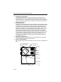
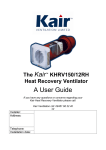
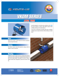
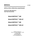
Heat Recovery
Ventilation Systems
OWNER’S GUIDE
® U.S. Registered Trademark
Copyright © 2002
All Rights Reserved
69-1657
HEAT RECOVERY VENTILATION SYSTEMS
CONTENTS
Introduction . . . . . . . . . . . . . . . . . . . . . . . . . . . . . . . . . . . . . . . . . . . . . . . . . . . . . . . . .3
Feeling right at home . . . . . . . . . . . . . . . . . . . . . . . . . . . . . . . . . . . . . . . . . . . . . . . . .3
What your Heat Recovery Ventilation System consists of . . . . . . . . . . . . . . . . . . . . .3
Operating your Heat Recovery Ventilation System. . . . . . . . . . . . . . . . . . . . . . . . . . .5
Getting the most from your Heat Recovery Ventilation System . . . . . . . . . . . . . . . . .6
Maintenance Instructions for your Heat Recovery Ventilation System . . . . . . . . . . . .7
Troubleshooting . . . . . . . . . . . . . . . . . . . . . . . . . . . . . . . . . . . . . . . . . . . . . . . . . . . .10
Limited Warranty. . . . . . . . . . . . . . . . . . . . . . . . . . . . . . . . . . . . . . . . . . . . . . . . . . . . 11
69-1657
2
HEAT RECOVERY VENTILATION SYSTEMS
Introduction
We take it for granted that our homes will protect us from the elements, but because of
tighter, better quality home construction, our indoor environment may be exposing us
to unacceptable levels of the very things we are trying to escape. Excessive heat,
dryness, humidity, toxic gases and dust contaminants can be sealed in securely by
weatherproofing.
So what’s the forecast for indoors?
Today’s indoor forecast is stormy weather for many homeowners. But rapid clearing
and fresh breezes are just around the corner!
Feeling right at home
Unlike what the outdoors brings us, you can have control of indoor conditions.
Temperature, humidity levels and air quality can all affect physical health, mental
attitude, general comfort and energy savings. With today’s technological advances,
you can achieve a totally comfortable indoors.
After all, people look to their homes as a place to escape the stress of work, a busy
lifestyle and an increasingly polluted outdoor environment. Creating a perfect indoor
climate is becoming critical to feeling right at home.
The Total Comfort System Heat Recovery Ventilation System removes stale, unhealthy
air and replaces it with a stream of fresh air. Its powerful centrifugal blowers bring fresh
air into your home and at the same time, exhaust stale humid air in an equal amount.
Both incoming and outgoing airstreams pass through a heat exchange core where the
energy from the exhaust air is efficiently transferred to the incoming fresh air. An air
duct system supplies the fresh air brought in by the ventilator and distributes it
throughout your home. Another duct draws the existing stale, humid air back to the
ventilator and then exhausts it outdoors.
It’s really very simple ... and remarkably effective!
What your Heat Recovery Ventilation System
consists of ...
1.
2.
Air Circulation Pan and Motor
Inside the casing are two fans, one for exhaust and one for fresh air supply. The
electric motor that operates the fan is 1/15 hp to 1/20 hp (depending on the ventilator model) and uses the same amount of power as a 100 watt lightbulb.
Air Filters
There are two permanent washable air filters in your ventilator. The filters lower
the amount of dust and outside particulates entering the ventilator core and your
fresh air supply.
3
69-1657
HEAT RECOVERY VENTILATION SYSTEMS
3.
4.
5.
6.
Condensate Tray and Drain
Condensation normally forms on the heat exchange core during the cold
weather (below 29°F or -2°C). Moisture can build up when the warm air from
your home comes in contact with the cold air from outside. The tray collects the
moisture and funnels it to the drain. The drain pans are made of therrnoformed
plastic for easy cleaning.
Defrost Mechanism
The built-in defrost mechanism will remove frost which can accumulate in colder
weather (21°F [-6°C] and colder). The type of defrost mechanism used is known
as “damper style”. This consists of an electronically controlled damper door
(attached to a small electric motor) that moves to block off the outside cold air
entering the ventilator. If the outside temperature drops below 27°F (-3°C), the
defrost timer is activated. The timer activates the motor driven damper door
mechanism which temporarily moves to close off the outdoor air supply and
opens another port on the ventilator that allows warm indoor air to enter the core
to help the defrost. Approximately three minutes after the defrost cycle is activated, the timer will signal the damper to return to its original position for a
2.7 minute period. The defrost cycle will repeat until the outside temperature
rises above 27°F (-3°C).
Thermally Conductive Core
The cross flow heat recovery core transfers heat between the two airstreams.
The core removes easily for cleaning or service.
Controls - Speed Control
Easy operation, simply rotate the ventilator fan speed control to your desired setting.
DEFROST PORT (NON-DUCTED)
DAMPER DEFROST
(MOTOR AND DOOR)
CORE INSTRUCTIONS
HEAT EXCHANGE CORE
CABINET
DUCTING
(4 PORTS)
FILTERS (2)
MAIN MOTOR
SQUIRREL
CAGE FAN
H CHANNEL
(CORE GUIDE) (4)
DRAIN PANS
DRAIN P TRAP
INSULATED
ACCESS DOOR
DOOR KEEPER PLATE (2)
FILTER CLIPS (2)
DRAIN LINE
69-1657
4
M11705A
HEAT RECOVERY VENTILATION SYSTEMS
Operating your Heat Recovery Ventilation System
Changing Fan Speed
The control fan speed is conveniently located on the ventilator. The rotary fan speed
control knob can be manually set from the off (standby) position through speeds 1 to 4.
Note the fifth speed (high) is accessible only by a remote control.
Off/standby mode may be used if intermittent ventilation is desired. In the off/standby
position, the ventilator will not function until energized by a remote control, see
information below.
It is up to the individual homeowner to set their system to a speed which they find
comfortable. If you feel your house is stuffy or there is an above average occupancy
rate, you may need to increase your ventilation. In most applications a low to medium
speed setting is comfortable.
RECOMMENDED
MAINTENANCE
POWER CORD
4-SPEED CONTROL
WITH STANDBY POSITION
PRODUCT
IDENTIFICATION LABEL*
*NOTE: THIS INFORMATION IS VERY IMPORTANT WHEN MAKING
INQUIRIES ABOUT YOUR ERV.
M11704A
Connecting a Remote Device
Your ventilator comes equipped with a low voltage terminal strip for connection to
several optional control devices.
5
69-1657
HEAT RECOVERY VENTILATION SYSTEMS
EXTERNAL REMOTE WALL CONTROL (DEHUMIDISTAT)
The dehumidistat (connected to your ventilator) is designed to control the operation of
the ventilator fan to help keep the humidity level in your home comfortable. If an
independent humidifier is installed and set at 30% (a normal indoor winter level) then
the dehumidistat (for the ventilator) should be set at least 10% higher, in this case
40%. With the ventilator operating on low speed and no one is home to produce
humidity, the humidifier will keep the humidity level to its setpoint. If the humidity levels
rise (due to occupant activity) above the 40% level, then the dehumidistat will
automatically increase the speed of the ventilator fan to high until the humidity level
falls below 40%.
TIMER
For your convenience, Total Comfort System provides a timer control that can fit a
wide variety of needs, for example, exhaust humid air from the bathroom or kitchen
(see the installation guide for selection and part numbers).
WALL SWITCH
A wall switch can also be used to switch your ventilator fan speed to high. The fan runs
at high speed until the wall switch is turned off.
When any remote device is activated the ventilator will run at high speed. All remote
devices must be in the off position to return the fan to the speed manually selected on
the rotary fan speed control knob.
Getting the most from your Heat Recovery Ventilation System
HOW MUCH VENTILATION DO I NEED?
During the seasons that your windows and doors are closed (winter and summer if you
have air conditioning), the ventilator should operate continuously when the home is
occupied, and either continuously or intermittently when not occupied.
For most installations, the ventilator will normally be set to operate continuously on low
speed with the option of going to high speed as the need arises. For example, if you
are entertaining and there is a large number of people present (some may be
smoking), the ventilator should be switched to high speed.
YOUR VENTILATOR MAY BE SET TO HIGH SPEED BY:
1. selecting the highest speed on the ventilator or
2. if the system includes an optional remote control, switch it to the On position.
NOTE: To set the dehumidistat, refer to the previous section of this booklet. To operate other remote devices, refer to the device owner’s manual.
69-1657
6
HEAT RECOVERY VENTILATION SYSTEMS
Maintenance Instructions for your Heat Recovery Ventilation
System
WARNING
Electrical Shock Hazard.
Can cause personal injury or equipment damage.
Disconnect power supply before performing maintenance.
The Heat Recovery Ventilation System must be maintained on a regular basis for best
efficiency. Honeywell recommends that the ventilator be cleaned and checked at least
twice a year, preferably at the beginning of each heating and cooling season.
Check and Clean
EXTERIOR HOODS
Exterior hoods should be inspected at least once a month. Be sure exhaust and fresh
air supply hoods are not blocked up or restricted by leaves, grass or snow. In winter, it
is especially important to make sure snow is not blocking the hoods or that frost has
not built up on the wire mesh (bird screen).
WARNING
Can cause personal injury or equipment damage.
Hood blockage can cause a change of pressure in building which can lead to
possible spillage from combustible appliances.
AIR FILTERS
Air filters should be cleaned twice a year. The standard filters supplied with your
ventilator are removable and washable.
1.
2.
3.
4.
Open access door and slide out core. Refer to Core Maintenance section for
cleaning instructions.
Remove filter clip.
Remove filters from the core and rinse with water or a combination of soap and
water. Do not clean in a dishwasher.
After cleaning, place filters (wet or dry) back in their position and reattach the
retaining clip.
7
69-1657
HEAT RECOVERY VENTILATION SYSTEMS
CORE
Clean the core twice each year.
FILTER CLIP
FILTER
CORE GUIDE
MANUAL CONTROL MODEL
1.
M11702A
Open the access door and carefully grip the ends of the core and pull evenly outward. The core can be snug, but it will slide out of the cabinet.
NOTE: Do not handle the fins because damage can occur.
2.
3.
4.
5.
Once out of the cabinet, remove the filters (refer to Air Filter Maintenance section).
Wash the core in warm soapy water—do not use a dishwasher.
Reinstall the clean filters.
Reinstall the clean core.
NOTE: Do not detach the foam on the ends of the core or the core label, water does
not damage them.
To install the clean core:
1. First mount the bottom core guide into the bottom H channel.
2. Mount either side core guide, followed by the other side.
3. Mount the top core guide into the top H channel.
4. With all four comers in place and the core straight and even, push on the core
center until the core slides to the back of the cabinet.
NOTE: The core will appear to stick out from the cabinet approximately 1/8 in.
(3mm). It is designed this way, so that the access door will fit tightly against
the core.
69-1657
8
HEAT RECOVERY VENTILATION SYSTEMS
DRAIN LINE
Clean the drain line once a year.
1.
2.
Inspect the drain line, drain spout and P trap for blockage, mold or kinks.
Flush with warm soapy water and replace if worn or bent, or if it can not be
cleaned.
GENERAL MAINTENANCE
Twice a year wipe down the inside of the cabinet with a damp cloth to remove dirt,
bugs and debris that can be present.
FANS
If the fans accumulate dirt, it could cause an imbalance and excessive vibration of the
ventilator. A reduction in air flow can also occur. In a newly constructed house, this
often happens within the first year due to heavy dust residue in the entire system. It
can also occur periodically depending on the outdoor conditions. If you suspect that
service is required, please contact the ventilator installer or your local HVAC
contractor.
9
69-1657
HEAT RECOVERY VENTILATION SYSTEMS
Troubleshooting
Lack of power to the ventilator:
• power failure of electrical box.
• loose or unplugged power cord.
• faulty breaker or fuse in home’s electrical panel.
• call your installation contractor.
Power to the ventilator, but no fan operation:
• ventilator is in standby mode and optional remote dehumidistat is set to OFF or the
humidity setting is higher than room humidity.
• door Is not closed properly, the safety interlock switch will keep the ventilator off.
Check that the access door is firmly closed and latched.
• refer to operating instructions.
• call your installation contractor for service.
Lack of Speed Control:
• let the remote device continue its time setting or manually adjust it to gain speed
control.
• test the speed control on the ventilator by turning the variable speed control knob to
its highest setting.
• call your installation contractor for service.
69-1657
10
HEAT RECOVERY VENTILATION SYSTEMS
Limited Warranty
York International, Unitary Products Group (UPG) warrants this product to be free from defects in the
workmanship or materials, under normal use and service, for a period of one (1) year from the date of purchase
by the consumer. If, at any time during the warranty period, the product is defective or malfunctions, UPG shall
repair or replace it (at UPG’s option) within a reasonable period of time.
This warranty does not cover removal or reinstallation costs.This warranty shall not apply if it is shown by UPG
that the defect or malfunction was caused by damage which occurred while the product was in the possession
of a consumer.
UPG’s sole responsibility shall be to repair or replace the product within the terms stated above. UPG SHALL
NOT BE LIABLE FOR ANY LOSS OR DAMAGE OF ANY KIND, INCLUDING ANY INCIDENTAL OR
CONSEQUENTIAL DAMAGES RESULTING, DIRECTLY OR INDIRECTLY, FROM ANY BREACH OF ANY
WARRANTY, EXPRESS OR IMPLIED, OR ANY OTHER FAILURE OF THIS PRODUCT. Some states do not
allow the exclusion or limitation of incidental or consequential damages, so this limitation may not apply to you.
THIS WARRANTY IS THE ONLY EXPRESS WARRANTY UPG MAKES ON THIS PRODUCT. THE DURATION
OF ANY IMPLIED WARRANTIES, INCLUDING THE WARRANTIES OF MERCHANTABILITY AND FITNESS
FOR A PARTICULAR PURPOSE, IS HEREBY LIMITED TO THE ONE YEAR DURATION OF THIS
WARRANTY. Some states do not allow limitations on how long an implied warranty lasts, so the above limitation
may not apply to you.
This warranty gives you specific legal rights, and you may have other rights which vary from state to state.
If you have any questions concerning this warranty, please write Unitary Products Group Consumer Relations,
5005 York Drive, Norman, OK 73069 or call 1-877-874-7378.
11
69-1657
Automation and Control Solutions
Honeywell
1985 Douglas Drive North
Golden Valley, MN 55422
69-1657 G.H. 10-02
Honeywell Limited-Honeywell Limitée
35 Dynamic Drive
Scarborough, Ontario
M1V 4Z9
Printed in U.S.A. on recycled
paper containing at least 10%
post-consumer paper fibers.
www.honeywell.com/yourhome