1
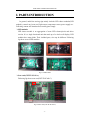
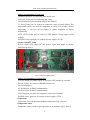
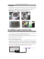
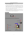
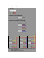
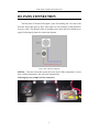
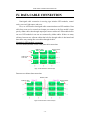
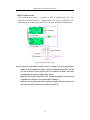
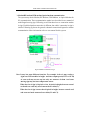
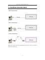
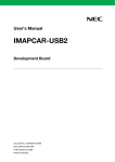
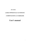
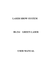
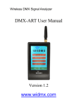
ELECTRIC CONNECTION
Series Outdoor E2000
LED ELECTRONIC DISPLAY
©All Right Reserved
Revision: 1.0
ELECTRIC CONNECTION MANUAL
• CATALOG
I. PARTS INTRODUCTION ............................................................................................................3
II. POWER CABLE CONNECTION ...............................................................................................5
III. FANS CONNECTION ................................................................................................................9
IV. DATA CABLE CONNECTION ................................................................................................10
V. SYSTEM CONNECTION..........................................................................................................15
VI. APPENDIX ...............................................................................................................................16
Appendix A: File Log .............................................................................................................16
-2-
ELECTRIC CONNECTION MANUAL
I. PARTS INTRODUCTION
In general, multi-line moving sign mainly includes LED cluster modules(LED
modules), control card, scan card, light sensor, temperature sensor, power supply etc..
Following content will introduce these mainly parts simply.
¾ LED modules
LED cluster module is an aggregation of some LED clusters/pixels and driver
circuits. It is a single functional unit that made up of a whole wall display. LED
modules have many kinds. Their included parts, size may be different. Following
fig shows several LED modules.
Fig1.1 LED module
¾ Scan card(CST-TP-SCAN-C)
Following fig shows scan card(CST-TP-SCAN-C).
J3
OUT1
JP1
JP2
IN1
OUT2
OUT3
OUT4
OUT5
OUT6
IN2
OUT7
OUT8
Power1
Fig1.2 Scan card (CST-TP-SCAN-C)
-3-
ELECTRIC CONNECTION MANUAL
Mainly port information of scan card:
IN1&IN2: Input port, for connecting with control card.
JP1: Light_Sensor port, for connecting light sensor.
JP2: Download port, for download file(pof) into EPM570.
J3: Protect_Temp port, for connect to temperature sensor of inside cabinet. This
temperature sensor is for check the temperature in cabinet. If it exceeds a defined
temperature, it will turn off the display or debase brightness of display
automatically.
OUT1~OUT8: Output port, for connect to LED modules. Output signal to LED
modules.
POWER1: Power input port, for connect to power supply(+5V DC).
¾ Control card(MTP_M04)
Receive signal from control PC and process signal then output to display.
Following fig show it.
JP1
JP3
JP7 JP8
JP5
JP2
JP6
JP4
Power
JP10
Fig1.3 Control card (MTP_M04)
Mainly port information of control card:
JP1~JP4: Output port, output signal, for connect to LED modules or scan card.
JP5: IR_IN Port, For connect to IR(Infra-red) Receiver.
JP6: Download port.
JP7: RS422 port, for RS422 communication.
JP8: RS232 port, for RS232 communication.
JP10: Temp port, for connect to temperature sensor(used in outside).
POWER: Power input port, for connect to power supply(+5V DC).
¾ Light sensor
Light sensor is used for automatic brightness adjustment. Fig1.4 shows it.
¾ Temperature sensor
Temperature sensor is used for get temperature of environment. Fig1.5 shows it.
-4-
ELECTRIC CONNECTION MANUAL
¾ Power supply
Converts AC line voltage from the load centre to low DC voltage for control
boards and LED cluster modules. All the power supplies are switching power
supply. There are many kinds power supply. Fig1.6 shows a power supply.
¾ IR Receiver: Receiver IR control signal from IR remote control.
Light Sensor
Fig1.4 Light sensor
Fig1.5 Temperature sensor
IR Receiver
Fig1.6 Power Supply
Fig1.7 IR receiver
II. POWER CABLE CONNECTION
All power come into LED moving sign through a power inlet, and connected
with power supply to supplied power for LED modules and cards.
Power cable connection includes two parts: outside power cable connection and
in LED moving sign power cable connection.
¾ Power cable connecting for outside
The power cable connection for outside is very simply. There need have electrical
outlet (a Plug AC female) near the moving sign installed. User only need plug the
plug male onto the plug AC female. The plug male is connected with LED moving
sign by a power cable from the power input port on cabinet. The plug AC female is
form power source. Following fig shows the power cable connection.
Plug onto
Cabinet
Plug
Power inlet
Fig2.1 Power connection of outside
-5-
Electrical outlet
ELECTRIC CONNECTION MANUAL
¾ Power cable connecting for inside
After power input cabinet, it always connect with surge protective device for safe,
then connect to power supplies by power cable (Sometimes it connect to power
supply without surge protective device). Power supply provides power for LED
modules and cards, so there need connect power supply to LED modules or cards
by power cable. One power supply may provide power for many LED modules. In
general, each row’s cabinets need one route power line.
Following, we will introduce how to connect power cable in LED moving sign. It
may has some difference in fact such as in cable’s color, number of power supply
etc.. But their connection is similar to following described.
Power input guide
Power inlet on cabinet:
Power Inlet
Power input cabinet includes two states as following figs show.
N L G
To power supply
Termination Block
To power supply
Power inlet
Surge Protective
Device
AC Input
No Surge Protective Device
Breaker
Include Surge Protective Device
-6-
ELECTRIC CONNECTION MANUAL
Power supply connecting guide
Power Supply
There are three states may be encountered.
¾ Only a power supply connection guide
¾ More than one power supply connection guide
…
¾ More than one cabinet connection guide
Cabinet n#
Cabinet 2#
Cabinet 1#
NOTE: Number of power supply for each sign are different, but their connection is similar to
one state of above described.
The color of cable may be different from fact.
-7-
ELECTRIC CONNECTION MANUAL
Example for power supply connection
The example below shows a big moving sign. It includes many cabinets, each cabinet
installed three power supplies. These cabinets arranged many rows and each row has
one route power line coming into.
Fig2.2 Example for power supply connection
Note: “X” denote a discretional letter.
In fact, the moving sign has some different from above example, but the
connection is as similar as it.
-8-
ELECTRIC CONNECTION MANUAL
III. FANS CONNECTION
The back door of cabinet has designed a space for installing fan. User only needs
fixed the fan on that space by bolt. Then connect it with a thermal switch (KSD301)
by power cable. The thermal switch is installing on the plate that has installed power
supply. Following fig shows the connection diagram.
Fig3.1 Fans connection diagram
KSD301--- Thermal switch that control fans turn on/off. When temperature is more
than a defined temperature, fans will work automatically.
Following fig is an example for fans connection.
Fans
KSD301
-9-
Power supply
ELECTRIC CONNECTION MANUAL
IV. DATA CABLE CONNECTION
Data/signal cable connection in moving sign includes LED modules, control
cards, scan card, light sensor and so on.
First, we will describe data/signal cable connection between LED modules. Data
cable from scan card or control card output port connect to the first module’s input
port by ribbon cable, then through output port connect with next LED modules that in
one row. LED modules in one row are connected by ribbon cables. If there are many
cabinets, between two adjacent cabinet has hole for through cables in horizontal and
data cables may coming into next cabinet through the hole.
Example for LED modules connection
The first cabinet(installed control cards) data cable connection:
Ribbon cable
Ribbon cable
Row 1
Cable from Row 2
scan card
Row 3
Fig4.1 LED modules connection(I)
Between two cabinets data connection:
Ribbon cable
Ribbon cable
Ribbon cable
Fig4.2 LED modules connection(II)
- 10 -
ELECTRIC CONNECTION MANUAL
Above contents has described data cables connection for LED modules.
Following will introduce control system connection in moving sign. The control
system connection has some difference with different communication mode and
different moving sign. In general, system uses RS232 communication mode or RS422
communication mode. Following give an example for these modes connection.
¾ RS232 communication
In general, the moving-sign use outdoor need light sensor for brightness control.
So the control system must have scan card. Following fig shows the general
connection for RS232 communication.
C1
C2
Fig4.3 RS232 connection in sign
Note: It may has some different from fact. For example, in fact, it may not has
eight rows LED modules in height. And these output ports(OUT1 to OUT8)
of scan card may not use up but only use someone of them. And some
moving sign may not have temperature sensor.
When the size of sign is 16 pixels or less 16 pixels in height, between control
card and scan card only need connected one cable(C1).
When the size of sign is more than 16 pixels in height, between control card
and scan card need connected two cables(C1 and C2).
- 11 -
ELECTRIC CONNECTION MANUAL
¾ RS422 communication
This communication mode is as similar as RS232 communication. The only
different from RS232 mode is communication with PC by RS422(JP7) port.
Following fig shows the general schematic connection for RS422 communication
C1
C2
Fig4.4 RS422 connection in sign
Note: It may has some different from fact. For example, in fact, it may not has
eight rows LED modules in height. And these output ports(OUT1 to OUT8)
of scan card may not use up but only use someone of them. And some
moving sign may not have temperature sensor.
When the size of sign is 16 pixels or less 16 pixels in height, between control
card and scan card only need connected one cable(C1).
When the size of sign is more than 16 pixels in height, between control card
and scan card need connected two cables(C1 and C2).
- 12 -
ELECTRIC CONNECTION MANUAL
¾ Modem/RF modem/GSM modem/Optical modem communication
The system may choice Modem, RF Modem, GSM Modem, or Optical Modem for
PC communication. These communication modes have described in user manual of
multi-lingual moving sign. Following we will introduce how to connection modem
in sign. Each kind modem connection is different, but cables’ connection in sign is
similar. Following fig shows the general schematic connection diagram for modem
communication. More information refers to user manual for this system.
C1
C2
Fig4.5 Modem connection in sign
Note: It may has some different from fact. For example, in fact, it may not have
eight rows LED modules in height. And these output ports(OUT1 to OUT8)
of scan card may not use up but only use someone of them. And some
moving sign may not have temperature sensor.
When the size of sign is 16 pixels or less 16 pixels in height, between control
card and scan card only need connected one cable(C1).
When the size of sign is more than 16 pixels in height, between control card
and scan card need connected two cables(C1 and C2).
- 13 -
ELECTRIC CONNECTION MANUAL
¾ TCP/IP communication
This communication need TCP/IP adapter. It is a extend communication mode of
RS232. In moving sign, cable connection of this mode is simply. Following fig
shown is the general schematic connection for this communication.
C1
C2
Fig4.6 TCP/IP connection in sign
Note: It may has some different from fact. For example, in fact, it may not have
eight rows LED modules in height. And these output ports(OUT1 to OUT8)
of scan card may not use up but only use someone of them. And some
moving sign may not have temperature sensor.
When the size of sign is 16 pixels or less 16 pixels in height, between control
card and scan card only need connected one cable(C1).
When the size of sign is more than 16 pixels in height, between control card
and scan card need connected two cables(C1 and C2).
- 14 -
ELECTRIC CONNECTION MANUAL
V. SYSTEM CONNECTION
¾ RS232 communication
¾ RS422 communication
¾ Modem communication
Note: If user wants to know more communication mode, please refer to user manual
of multi-line moving sign.
- 15 -
ELECTRIC CONNECTION MANUAL
VI. APPENDIX
Appendix A: File Log
File No.
Descriptions
- 16 -