1
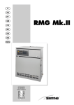
KASTOR KS Series
Woodburning Sauna Stove
Models KS-12, KS-20, KS-27, KS-37
Installation and Operation Instructions
KASTOR KS- series wood burning sauna stoves installation and usage manual (KS-12, KS-20, KS27, KS-37)
Virhe. Kirjanmerkkiä ei ole määritetty.
1. Before you install ......................................................... Virhe. Kirjanmerkkiä ei ole määritetty.
1.1. Package contents and its inspection .................... Virhe. Kirjanmerkkiä ei ole määritetty.
1.2. Important matters and regulations ....................... Virhe. Kirjanmerkkiä ei ole määritetty.
2. Installation and preparation for use ............................ Virhe. Kirjanmerkkiä ei ole määritetty.
2.1. Preparing for use and burn-in .............................. Virhe. Kirjanmerkkiä ei ole määritetty.
2.2. Stones and their arrangement .............................. Virhe. Kirjanmerkkiä ei ole määritetty.
2.3. Stove base ............................................................ Virhe. Kirjanmerkkiä ei ole määritetty.
2.4. Safety distances and protections ......................... Virhe. Kirjanmerkkiä ei ole määritetty.
2.5. Connecting the stove to a brick chimney ............ Virhe. Kirjanmerkkiä ei ole määritetty.
2.6. Connecting to a Kastor chimney ......................... Virhe. Kirjanmerkkiä ei ole määritetty.
2.7. The stove door and changing the opening directionVirhe. Kirjanmerkkiä ei ole määritetty.
2.8. Air guide plate ..................................................... Virhe. Kirjanmerkkiä ei ole määritetty.
2.9. General directions to prevent damage ................. Virhe. Kirjanmerkkiä ei ole määritetty.
3. Using the stove ............................................................. Virhe. Kirjanmerkkiä ei ole määritetty.
3.1. Fuel ...................................................................... Virhe. Kirjanmerkkiä ei ole määritetty.
3.2. Adjusting the air flow .......................................... Virhe. Kirjanmerkkiä ei ole määritetty.
3.3. Adjusting the heat output .................................... Virhe. Kirjanmerkkiä ei ole määritetty.
4. Maintenance .................................................................. Virhe. Kirjanmerkkiä ei ole määritetty.
4.1. Cleaning the stove ............................................... Virhe. Kirjanmerkkiä ei ole määritetty.
4.2. Ash removal ........................................................ Virhe. Kirjanmerkkiä ei ole määritetty.
4.3. Sweeping ............................................................. Virhe. Kirjanmerkkiä ei ole määritetty.
4.4. Removal and cleaning of the stove's glass .......... Virhe. Kirjanmerkkiä ei ole määritetty.
5. Troubleshooting ........................................................... Virhe. Kirjanmerkkiä ei ole määritetty.
6. Warranty and manufacturer identification .................. Virhe. Kirjanmerkkiä ei ole määritetty.
Инструкция по монтажу и эксплуатации дровяных каменок серии KASTOR KS (KS-12, KS-20,
KS-27, KS-37)
38
1. ПЕРЕД МОНТАЖОМ ........................................................................................................... 39
1.1. Содержание комплекта каменки и его проверка............................................................ 39
1.2. Учесть до монтажа ............................................................................................................ 39
2. ПОДГОТОВКА К ЭКСПЛУАТАЦИИ И МОНТАЖ ............................................................... 39
2.1. Подготовка каменки к эксплуата ции и первая растопка .............................................. 39
2.2. Камни и их расположение ................................................................................................ 40
2.3. Основание каменки ........................................................................................................... 40
2.4. Безопасные расстояния и защита..................................................................................... 41
2.5. Присоединение каменки к кирпичному дымоходу........................................................ 42
2.6. Присоединение к модульному дымоходу Kastor ........................................................... 44
2.7. Дверца каменки и изменение направления открывания ............................................... 44
2.8. Направляющая заслонка воздуха..................................................................................... 44
2.9. Общие инструкции по предотвращению повреждений ................................................ 45
3. Эксплуатация каменки ...................................................................................................... 45
3.1. Топливо .............................................................................................................................. 45
3.2. Регулирование тяги ........................................................................................................... 45
3.3. Регулирование мощности нагрева ................................................................................... 46
4. ОБСЛУЖИВАНИЕ ............................................................................................................... 47
4.1. Чистка каменки.................................................................................................................. 47
4.2. Удаление золы ................................................................................................................... 47
4.3. Прочистка каменки ........................................................................................................... 47
4.4. Снятие и очистка стекла каменки .................................................................................... 47
5. ПРОБЛЕМЫ И ИХ РЕШЕНИЕ ............................................................................................ 48
6. ГАРАНТИЯ И СВЕДЕНИЯ ОБ ИЗГОТОВИТЕЛЕ .............................................................. 49
2
KASTOR KS- series wood burning sauna stoves
installation and usage manual
(KS-12, KS-20, KS-27, KS-37)
Please save these instructions for later use!
Once the installation is done, this manual should be given to the sauna’s owner or the
person in charge of running it.
Please read these instructions prior to installation and first use!
KASTOR WOOD BURNING SAUNA STOVES
We thank you for your confidence in Kastor’s products. We have manufactured wood burning
sauna stoves for nearly a century now, longer than any other company in the world. Over these
years, we have learned a lot about fire, its handling and its precariousness. Anyone can light a
fire, but nurturing it is nearly a form of art. We have two guidelines in design and manufacturing:
A master’s touch leaves nothing extraneous and a master’s touch cannot be achieved with low
grade material. Our products are simple and reliable, although their elegant form is based on
solutions born from decades of experience and the latest technology.
QUALITY MATERIAL
Our products contain only the best possible material, procured from reliable suppliers we have
gathered over the years. The steel is Finnish structural steel from Ruukki, which can be bent into
various solutions while retaining its hardness due to its uniform quality. Our glass covers are
Ceram glass, which can withstand up to 800 °C while still allowing the fire’s warm glow to spread
into the room.
WE KNOW FIRE
Our products are heavy, which by itself is a sign of fireproof construction. Still, it is not the steel’s
thickness but its correct use that is important. One needs to know how fire behaves. The hottest
and most stressed part is not necessarily directly above the fire, depending on how the heat is
being channelled. The fire must also be supplied with air to ensure optimally clean burning and
economical heating.
SUPERIOR TECHNOLOGY
Our stoves can be fully heated with just one load of wood and they retain warmth long after the
flame has died down. This unique property is the sum of many factors: High quality material, the
Coanda- air circulation system, the air guidance sheet, the large and deep stone compartments
and the sturdy doors. Read more about these and our other technical innovations as well as our
comprehensive installation supplies at www.kastor.fi or in our prospectus.
3
1. Before you install
Inspect both product and the contents of the package as soon as you receive them. Report any
transport damages to the deliverer.
1.1. Package contents and its inspection
The stove package contains:
• Stove
• Within the fire compartment
o Installation instructions
o Grate
o Air guide plate
o Connection pipe
o 2 adjustment legs
o Door handle, Attachment screws and washers
• Two steel caps (one on the foremost sweeping hole and another on the back wall flue
hole, which bolted into place with a screw driven through the intermediate mantle).
1.2. Important matters and regulations
During installation and use these instructions and all relevant official regulations must be
followed. The sauna stove must not be used for any other purposes such as drying clothes,
heavy heating during building etc. The stove must also never be covered in any way during use
or when it is warm.
Also check the following aspects and their influence on your choice of stove installation location:
o Safety distances to flammable and non-flammable structures (Chapter 2.3. and
2.4.)
o Location of chimney connection (height from floor of any existing chimney
connection or installation route of any new chimney pipe)
o Floor material (flammable, non-flammable, tiled and waterproofed)
2. Installation and preparation for use
2.1. Preparing for use and burn-in
•
•
•
•
•
•
•
•
•
Install door handle according to chapter 2.7.
Place the stove outdoors on a non-flammable surface
o without stones
o tank, if any, filled with water
Remove any decals and protective plastic sheeting.
Check that the grate and air guide plate (see chapter 2.8.) are in place.
Install the connection pipe delivered with the package into the backmost flue opening on
top of the sauna stove or the hole in the back wall. In JK models it goes into the hole
nearest the wall on top of the stove.
The caps delivered with the stove are required to close the other holes. The hole in the
back wall must also be capped.
Burn-in: The purpose of the burn-in is to remove out of doors any flammable protective
coating substances and to harden the stove’s coating. Burn a few full loads of wood in the
fire compartment. Continue the burn-in until there are no more fumes rising from the
stove.
Once the stove has cooled down after the burn-in, move it into the sauna.
See to it that the sauna is well ventilated during the first couple of heating.
4
2.1.2 WATER TANK
Water tank cover
Lift off the water tank cover (remove protective plastic sheeting from the cover) and attach the
cover's handle knob with a screw in such a way that the knob is on the outside.
Water tank spout
To avoid damage during transport, the spout of the stove's water tank has been installed on the
inside. The delivery includes the spout, two gaskets and a nut. The spout should be attached on
the exterior of the water tank as follows (Picture 1):
•
•
•
•
•
•
•
Lift water tank from its place.
Place first gasket on the spout's winding.
Push spout into hole in the stove's mantle.
The second gasket is placed on the spout's winding on the inside of the mantle.
Lift water tank into its place and set its hole on the winding part of the spout.
Set the water tank's edge on the side support.
Place the nut on the spout's windings inside the tank and tighten with suitable tool.
2.2. Stones and their arrangement
Use peridotite or dunite or darkish natural stones with diameters of over 10 cm. always wash the
stones before installing them. They must not be stacked too tight or heaped up – arrange them
so that plenty of air can pass between them to warm the upper stones, as well. Fill the stone
compartment up to the edge, with flat stones in upright positions (Picture 2.2.). The maximum
stone capacity is about 60kg.
By adjusting stone size, amount and adding other types of stone you can balance the steam
consistency to suit the sauna and your preferences. Since these are highly individual, we cannot
give a general rule of thumb – you will find the right mix by trial and error.
For the stove’s proper functioning it is essential that the hot air circulates between the stones to
heat them quickly. If the stones are too small or improperly arranged, you will heat the sauna
instead of the stones!
2.3. Stove base
The stove must be installed horizontally, on a stable and unmoveable non-flammable or
fireproofed base. For this, you may either use Kastor’s separately sold protective stove base or a
concrete sheet with a minimum thickness of at least 60 mm with a slight incline towards the back
and a smooth surface.
The front corners of the stove are equipped with adjustment screws, with which it can be
straightened horizontally on an inclined. The adjustable legs are delivered in the equipment bag
in the stove’s fire compartment. Screw them into place and adjust as needed.
We do not recommend installing the stove directly on a tiled floor, as its moisture sealing, tile
glue etc. may contain components that are not heat resistant.
Fireproofing of the floor on flammable material:
400 mm in front of the stove
250 mm to the sides
250 mm behind the stove
(Or, at the sides and back up to a fireproofed wall; picture 2.3.).
5
2.3.1. Installation on wooden floor with a cast concrete base
On a wooden floor we recommend installation on a 60 mm thick, smoothly cast concrete slab,
which rises towards the back, with risers to provide a ventilation slit between it and the floor. The
stove is then straightened by adjusting the legs.
ATTENTION! Always check the carrying capacity of the wooden floor, as the loaded stove
weighs more than 100 kg.
2.3.2. Installation on tiled and waterproof floor
The Kastor protective stove base is sufficient, a separate fronting plate is not necessary.
2.4. Safety distances and protections
2.4.1. Safety distances
For stone walls, the safety distances are 50 mm from the stove’s outer surfaces, preferably 100
mm to achieve sufficient air circulation. This means the stove will fit a niche of stove width +
200mm (i.e. for the KS 20 that is 490 mm + 200mm = 690mm).
The safety distance to any flammable materials is 500mm from the stove’s outer surfaces. In
front of the stove, due to heat radiation and the working and maintenance space needed, 1,000
mm is a reasonable distance, but 500 mm is sufficient to ensure safety, if the panel in front of it
does not heat up beyond 85oC during the burn-in.
If the flue pipe starts off from the top of the stove with a no insulated connection pipe, the
required safety distance is 1,000 mm in all directions and 1,200 mm above.
The safe distance between a fitted water tank and the nearest flammable material is 150 mm.
These safety distances can be reduced by using protectors according to instructions given below.
These will enable you to install the stove in a space just 1,100 mm wide (I.e. for KS 20, the width
needed is 490mm + 250mm = 740mm).
When the distance from the stove upper surface is at least1,200 mm, the ceiling does not require
protection.
2.4.2. Reduction of safety distances
The required safety distances at the back and sides can be reduced by 50% using a single layer
of protection and by 75% with a doubled layer. The protection can be either a 1 mm thick metal
sheet or 7 mm of fibre-reinforced cement board (not gypsum board coated with paper or similar).
(Picture 2.4.2.)
A ventilation space of 30 mm must be left between wall and protector. The protector must be
detached from floor and ceiling (likewise between the plates for doubled protectors). If the sauna
has a flammable floor in front of the stove, the area to be protected extends 100 mm beyond the
door’s sides and a minimum of 400 mm in front of it. In this case, the protection must be at least
a 1 mm thick metal sheet.
If the stove is installed with one side and the back against a brick wall, safety distances of 50 mm
to the side and 50 mm at the back are sufficient. If it stands with its back and both sides next to
brick wall, 100 mm should be left on both sides to ensure air circulation. At the back, 50 mm
remains sufficient.
The safety distances around a no insulated connection pipe can be reduced in a similar manner.
The pipe’s insulated part within the sauna must always extend to 400 mm below the ceiling.
6
For chimneys, the minimum safety distances to flammable material differs from product to
product. Always check the manufacturer’s instructions. In case of doubt, approach your local fire
safety officials.
2.5. Connecting the stove to a brick chimney and instructions for JK stoves
The KS stove can be connected to a brick chimney from the back or the top. JK models can only
be connected from the top. For a brick chimney connection, the safety distances and protectors
named in chapter 2.4. and the chimney’s masonry regulations must be adhered to.
2.5.0. Connection from the rear, only in KS models
Make an opening in the brick chimney that is 2-3cm wider than the connection pipe.
Detach the stove's outer back mantle. Use a screwdriver to detach the plate covering the hole in
the inner back mantle. Move this covering plate onto the hindmost hole on top of the stove. Place
the connection pipe delivered with the stove in its rear wall opening. Push the stove into its place.
Make sure that the connection pipe settles well into the hole in the chimney. Tighten the space
between connection pipe and chimney with a flexible, fire-proof material such as fire wool.
Neaten the hole with a Kastor covering, available at your hardware store. The covering is
attached to the brick chimney surface with metal attachments or fireproof glue. (Picture 2.5.1.)
Stoves with extended feed doors must only be installed into walls made of non-flammable
material (brick, concrete etc.).The non-flammable material must be arranged around the door
extension as shown in picture 5. If there is a flammable floor in the room with the door, the area
requiring protection must extend 100mm beyond both sides of the door and at least 400mm in
front of it. The protective layer should be a metal sheet with a thickness of at least 1mm.
2.5.1 Stoves with an extended door
The floors of the sauna and the room into which the stove door opens must be on an equal level.
The room with the stove door may also be on a lower level, but never higher than the sauna's
floor!
The stove and its extension must be installed on a sturdy, immovable, fireproof, level
surface. A cast concrete base is the best choice. If the floor of the room with the door in it
is flammable, there must be a non-flammable protective layer (i.e. cast concrete or masonry) of
at least 60mm beneath the door extension. The fire protection measures on the door side must
also adhere to the instructions in chapter 2.3.
By adding fireproofing the stove and its door extension may also be installed on wooden
floors. Nevertheless, the dividing wall must be non-flammable (brick, concrete or similar). For the
sauna and the extended door, a concrete slab with a thickness of 60mm is usually acceptable
(remember to take care of moisture draining). The fireproofing on the sauna side floor must
extend 250mm in front of the stove, 250mm at its sides and 250mm behind it or, at the back and
sides, up to a fireproofed wall. The fire protection measures on the door side must also adhere to
the instructions in chapter 2.3.
In unclear cases consult the local fire safety officials.
2.5.2. INSTALLATION THROUGH THE WALL AND FITTING THE FRAME , KS-12–20-27-37
JK models, also with water tank
See also the instructions in chapter 2.6. concerning flue pipe installation.
Make sure that you have received the frame that belongs to the door extension (behind the
stove, between the packing hoop and the stove).
Installation through the wall:
• Make a hole in the wall. Its size should leave about 10-20mm of clear space all around
the door extension.
• Remove the stove door by taking the hinge pin off (note the 2 base plates between door
and frame).
7
•
•
•
•
•
•
•
•
•
•
Remove the ash door.
On the other side of the frame, remove the rivet from its hole in the upper part.
Install the stove from the sauna side and push it as far as possible through the wall, so
that the door extends about 40mm beyond the wall.
Insulate the gap between feed door and wall with fireproof mineral wool. Follow the
instructions of the mineral wool manufacturer!
Install the frame into place via the door (do not yet attach it to the wall).
Attach the door. Remember the base plates. At this point, you may choose the door's
opening direction.
Place the rivet in the upper part of the frame in the remaining hole.
Put the ash door into place.
Ensure that a gap of 5-10mm remains between extended door and the frame on top of it
to allow for heat expansion.
Attach the frame to the wall with six 5mm screws using metal attachments that are
embedded in the wall.
2.5.3. Connecting from the top
Make an opening into the brick chimney that is 2–3 cm larger than the connection pipe.
Use a 45° bent pipe for the connection from the top of the stove, which can be turned to align
with the chimney. Suitable 45° bent pipes are available at the hardware store. Extend the bent
pipe with an extension piece, if necessary. Install the stove’s own connection pipe in the doorside flue opening on top of the stove (the other opening is the sweeping hole, which must not be
used for the pipe!). The bent pipe is then attached to the stove’s own connection pipe. Saw the
bent pipe and any extension pipe down to a suitable size where necessary. Make sure the pipe
extends sufficiently into the chimney (but not so far that it blocks up the chimney).
Seal the empty space between connection pipe and chimney with flexible, fireproof material such
as stone wool. The lead-through is then tidied up with a Kastor covering plate, which is available
at your hardware store. The covering plate is attached to the wall with metal bolts or fireproof
paste. See picture 2.5.2.
2.6. Connecting to a Kastor chimney
The Kastor stove can be connected from the top to a factory built Kastor chimney.
Make sure to choose the correct chimney type with regard to your stove model, chimney height,
temperature class T 600, exterior circumstances etc. For best results we recommend that you
install a chimney valve, as well. Picture 2.6.
• Set the stove’s own connecting pipe into the stove’s door-side flue opening.
• Install a no insulated connection pipe and any necessary extension piping on top of the
connecting pipe. Where necessary, saw the connection pipe and the extension pipe down
to suitable size.
• The chimney valve goes between the insulated and no insulated sections or into the first
insulated pipe section.
• Continue from the chimney valve with an insulated pipe. The insulated pipe section must
start at least 400 mm beneath the ceiling. Follow the installation and usage instructions
for Kastor chimneys.
Remember to keep all safety distances to flammable and non-flammable materials named above.
Helo Oy does not guarantee the suitability and functioning of other manufacturers’ factory-built
chimneys with Kastor stoves. Helo Oy does not accept liability for the quality of other
manufacturers’ factory-built chimneys. The chimney must fulfil the requirements of temperature
class T 600.
8
2.7. The stove door and changing the opening direction
The opening direction is changed by turning the door upside down. The handle must also be
reversed. Open the handle's 2 attachment screws, turn the handle upside down and attach the
screws.
The opening direction is changed by turning the door upside down.
• Open the door and push the hinge pin out of the lower hole.
• Pull the pin downwards out of the upper hole to release the door. Remember the
washers.
• Turn the door into the desired position.
• Slip the hinge pin first into the sleeve's upper hole and the washers on top of the sleeve
onto the pin. (The risers on the pin must be at the lower end.)
• Slip the door's upper hole onto the hinge pin above the sleeve.
• Finally, guide the hinge pin into the lower holes of the sleeve and the door.
2.8. Air guide plate
In the back part of the stove’s fire compartment is a removable air guide plate. (Picture 2.8. /1.)
The stove must not be used without the guide plate! If it gets worn out through use, twisted or
otherwise damaged, it must be replaced.
Replacing the air guide plate
Remove the grate. Install the air guide plate in the fire compartments back so that its support part
is on the grate support. Check the plate’s condition regularly. (Picture 2.8. /2.)
2.9. General directions to prevent damage
When you bring the stove into the sauna, before you add the stones, burn a full load of wood in a
well ventilated sauna to burn off the last protective substances and harden the coating.
Once the outdoor burn-in has been performed, the stones arranged and the water tank, if
installed, filled, your Kastor stove is ready for use. Make sure that the air guide plate is in place
as shown in picture 2.8./2.
Please read and follow the instructions below:
• Remember to leave at least 10 cm of free air space as measured from the flame plate
downwards to aid the burning process.
• Do not heat immediately at full blast, if it is cold. The brick chimney might suffer damage.
• Do not throw water directly at the glass door.
• The stove’s operating life shortens, if it is constantly heated to a red glow.
• The stove’s working life will be shortened significantly, if it is subjected to salt water. Note
that in close proximity to the sea even well water may contain salt.
• Factors influencing the stove’s useful life are, among other things, how well its size is
suited to the sauna, the fuel used, how often it is used, failure to follow these instructions
and general carefulness.
• Kastor stoves have been very carefully designed and tested. On the basis of our studies,
we at Helo Oy know that if the stove suffers damage in a very short time (e.g. the walls
split or burn through, the top burns through etc.), the stove has not been used according
to instructions. Helo Oy does not take responsibility for damage through failure to follow
the user’s manual.
9
3. Using the stove
3.1. Fuel
Use only untreated wood in Kastor stoves, preferably sturdy split logs of various woods, such as
birch or alder. The logs should at most be 35 cm long. Wet or foul wood does not heat very well.
It is not permitted to burn treated wood, wood with nails, plywood, plastic, plastic coated
cardboard or paper in this stove. Fluid fuels must not be used even while starting the fire to avoid
dangerous flash fires. Do not burn full loads of very small wood such as shavings and splinters,
as they produce excessive heat for short durations.
The fuel logs must not be stored in the immediate vicinity of the stove. Remember the safety
distances. Only bring into the sauna as much wood as you can fit immediately into the fire
compartment.
3.2. Adjusting the air flow
The stove has been designed to work best when the chimney’s air suction is about 10–20 Pa. If
the chimney is tall, this optimal air suction limit is easily exceeded. This excess can be noticed as
follows:
• The air flow cannot be adjusted with the ash door, only the amount of air available for
burning.
• The flames reach into the connecting pipe and even up to the chimney.
• The humming noise of the burn feels loud.
• Looking through the glass door, the flames rage with great strength towards the stove’s
upper part.
• The sauna and/or stones do not heat up properly in less than an hour (although the stove
has the correct size).
When you light the fire, the chimney valve and ash compartment door must always be open.
Once the fire has taken hold and burns well, adjust the air flow with the ash compartment door.
Usually, depending on the draught, the ash door is kept open by about 0.5–2 cm.
The stove’s basic draught is just right, when the burning can be affected by the ash door and the
flames rise calmly. This brings the cleanest burning, although it warms up somewhat more slowly
than in a stronger draught.
If the basic draught is too strong, it can be adjusted by setting a fireproof piece of brick or an
optionally available draught adjustment plate inside the stove’s upper part, on top of the arched
flame plate. If that does not help, the basic draught may be adjusted with the chimney valve. Do
not close the chimney valve too much – carbon monoxide poisoning hazard!
3.3. Adjusting the heat output
The heat output is affected by the quality and amount of fuel. Do not burn excessively long logs
in the stove. Take care not to heat the stove constantly to a red glow.
3.3.1. A sauna bath on just one load of wood, lighting from below
•
•
•
•
Place two smallish logs lengthwise in the fire compartment.
Add some lighting aids between the logs and light them.
Then place a few logs crosswise on the previous ones.
Close the door and leave the ash compartment door open by about 3 cm.
10
Once these latest logs have burned some five minutes, straighten them into the grate direction
and fill the fire compartment lengthwise with solid split logs. Close the door and leave the ash
door open by 3 cm for a short while.
After this, slow down the burning by closing the ash door gap to 0.5–2 cm. During this heating
phase, the fire compartment walls should only heat up for a while to a red glow in their upper
parts. Usually, this will prepare the sauna for your bath in about 40–50 minutes, and you should
not need to add firewood during your stay.
3.3.2. A sauna bath on just one load of wood, lighting from above
Lighting from above is a departure from tradition. With this method, stove and stones heat up
slightly more slowly than with the usual way, but once you have found a good combination of
stove and chimney adjustments, the difference is not very big.
Lighting from above is more ecological, causes fewer emissions and raises more heat energy
from the firewood. As a result, you can bathe on less wood for a longer time.
•
•
•
•
•
•
•
Check that the chimney valve is wide open.
Use dry wood that has preferably been indoors for a day.
Fill the fire compartment with firewood up to the door’s upper edge.
Place ignition helpers on top, e.g. small sticks and a piece of bark.
Light the ignition helpers from the top.
Close the door and leave the ash compartment door open by 3 cm.
Once the fire has burned for 5–10 minutes, the burning can be adjusted by closing the
ash door to 0.5–2 cm. Restrict excessive draught with the chimney valve, if necessary.
During this heating phase, the fire compartment walls should only heat up for a while to a red
glow in their upper parts. Usually, this will prepare the sauna for your bath in about 50–60
minutes, and you should not need to add firewood during your stay.
3.3.3. Continuing the heating with a second load
Depending on how much you bathe, frost outside etc., you may need to continue the heating with
a second load.
Once the first load has turned to embers (in about 40–60 minutes, if the draught is right), place
sturdy logs lengthwise in the fire compartment. If you are not going into the sauna immediately
after adding the wood, leave the ash door gaping by a few millimetres. Now the fire should
remain just right for a long time. When you do go into the sauna, you can add a few logs, if
necessary.
4. Maintenance
4.1. Cleaning the stove
The stove’s surface can be cleaned with a mild cleaning fluid detergent solution by wiping down
with a soft, moist rag.
The glass doors are cleaned with Kastor’s Noki Pois cleaning fluid, which is available in hardware
stores.
4.2. Ash removal
Excessive ash shortens the grate’s lifespan and weakens the burning. Remove the ash while it is
cold, always before the next heating, using a metal container to avoid a fire hazard.
4.3. Sweeping
The hatches in the stone compartment are for sweeping (covered with lids).
The stove’s internals are cleaned through these hatches 2–6 times a year, depending on use.
11
If the stove is connected to the chimney from the top, soot will drop into it, which needs to be
removed.
4.4. Removal and cleaning of the stove's glass
The glass door must be treated with care. Do not slam it shut or uses it to push logs into the
stove. The glass doors are cleaned with Kastor’s Noki Pois cleaning fluid.
4.4.1. Changing a broken glass pane
•
•
•
•
•
•
Remove the door according to chapter 2.7.
Remove the glass splinters and the retainers.
Straighten the tongues in the corners of the laths.
Push the glass all the way into the upper lath and then into the lower one by adjusting the
glass. Centre it.
Push the locking springs into the lath ends and bend the tongues against the glass.
Attach the door to the stove.
5. Troubleshooting
If the stove or the sauna fails to work as you think they should, go through the following check
list.
First, to make sure you have chosen the correct stove for your sauna’s requirements, look
through the stove choosing instructions on our internet pages at www.kastor.fi -> “wood burning”
-> “select your stove”.
Smoke leaks into the sauna, bad draught.
Is the chimney valve open?
Is the connecting pipe attached tightly both to the stove and the chimney?
There mustn't be any air leaks.
Is the stove’s other flue opening closed tightly with the cap that came with the stove?
Is the flame plate in the upper part of the stove clean of ash?
Is the connecting pipe between stove and chimney clear of ash?
Is the chimney fully open?
In need of sweeping, stuffed with snow, winter cap on etc.
Is the chimney intact?
Cracks, weathered
Is the draught height (chimney height) sufficient with regard to the environment?
Nearby trees, a steep hill etc. requires more than 3.5. metres as measured from the
chimney floor.
Is the chimney’s size correct?
At least a half brick wide or, depending on stove model, a round chimney of 100 or 120 mm.
The stove stones do not heat up sufficiently.
Has the stove been fired sufficiently?
You should burn at least one compartment full of split, dry logs according to instructions.
Is there too much draught?
The flames reach into the connecting pipe, which is red hot, although the lower end of the
stove within the mantle is not red. See chapter 3.3. about draught adjustment and heat
output.
Is the draught too weak?
See chapter 3.3. about draught adjustment.
Correct amount of stones?
The stones should reach up to the edge of the stone compartment at the edges and be
heaped up only by half a stone in the middle.
Are the stones packed too tight?
The stones need to be stacked in such a way that there is enough air between them. See
chapter 2.2. “Stones and their arrangement”.
12
Are the stones good quality and the correct size?
Suitable stones are peridotite or dunite of a length of over 10 cm and not too flat.
The sauna does not get hot enough.
Is the sauna new or the wooden structure otherwise moist?
For instance, a new log cabin sauna warms up properly past 80oC only after a year.
Is the stove properly heated?
Has the stove been fired sufficiently?
You should burn at least one compartment full of split, dry logs according to instructions.
Is there too much draught?
The flames reach into the connecting pipe, which is red hot, although the lower end of the
stove within the mantle is not red. See chapter 3.2. about draught adjustment and heat
output.
Is the draught too weak?
See chapter 3.2. about draught adjustment.
Is the stove too big for the sauna?
Is the draught height (chimney height) sufficient with regard to the environment?
Nearby trees, a steep hill etc. requires more than 3.5. meters as measured from the
chimney floor.
Correct amount of stones?
The stones should reach up to the edge of the stone compartment at the edges and be
heaped up only by half a stone in the middle.
Are the stones packed too tight?
The stones need to be stacked in such a way that there is enough air between them. See
chapter 2.2.
Are the stones good quality and the correct size?
Suitable stones are peridotite or dunite of a length of over 10 cm and not too flat.
The sauna heats up quickly, but the stones remain cool.
Correct amount of stones?
The stones should reach up to the edge of the stone compartment at the edges and be
heaped up only by half a stone in the middle.
Are the stones packed too tight?
The stones need to be stacked in such a way that there is enough air between them. See
chapter 2.2.
Is the stove too big for the sauna?
Keep the ventilation valve open to remove excess heat, which gives the stones time to
warm up as well. This will extend the heating period slightly.
Are you heating the sauna correctly?
Read chapter 3 of these instructions carefully.
The water does not heat up properly in a stove with a water tank.
Is there too much draught?
The flames reach into the connecting pipe, which is red hot, although the lower end of the
stove within the mantle is not red. See chapter 3.2 about draught adjustment and heat
output.
Is the stove sized according to instructions?
Black flakes collect beneath the stove.
The stones may be weathered.
The flakes may be metal flaking off the stove. The stove has been heated too intensely at a
red heat.
The metal flakes off and the stove will break down prematurely.
There is a smell of sulphur in the sauna.
Traces of sulphur have remained on the stones from the quarry’s explosion or the stones
are naturally sulphurous.
13
6. Warranty and manufacturer identification
If the stove stands unused in a moist environment (such as a cold holiday cottage), it must be
inspected for any corrosion damage before use.
WARRANTY
Kastor products are of high quality and reliable. For its wood burning stoves, Helo Oy grants a 3
year warranty for its Kastor stoves covering manufacturing flaws.
This warranty does not cover any damage incurred through incorrect use that does not accord
with instructions. See chapter 3 of this manual.
MANUFACTURER
HELO OY, Tehtaankatu 5 - 7, 11710 Riihimäki, Finland
Tel. +358207560300, e-mail: [email protected]
14
7. Kuvat, bilder, pictures, pис
Kuva, bild, picture 1
15
Kuva, bild, picture, pис 2.2.
Kiuaskivien asettelu, läpileikkauskuva kiukaan kivitilasta.
Aseta kivet niin, että kivien väliin jää riittävästi ilmaa.
Placering av bastustenarna, genomskärningbild av ugnens stenmagasin.
Placera bastustenarna pä plats så att det blir tillräckligt med luft mellan stenarna.
Stone aggangement. Make sure that there is sufficient air between the stones.
Sectional view of the stove’s stone compartment.
Укладка камней, разрез отсека для камней. Камни укладывать так,
что между ними остается достаточно воздуха.
2.3. Kuva, bild, picture, pис.
Kastor- kiukaan asentaminen Kastor- suoja-alustaa käyttäen.
Montering av Kastor- bastuugn med Kastor- skyddsunderlag för ugn.
Installation of Kastor stove using the Kastor protective stove base.
Установки каменки Kastor на защитном основании Kastor.
1. Betonilattia tai kaakeloitu vesieristetty betonilattia
Betonggolv eller kaklat, vattenisolerat betonggolv
Concrete floor or tiled, waterproofed floor
Бетонный пол или гидроизоли рованный пол с плиткой
2. Kastor kiukaan suoja-alusta
Kastor skyddsunderlag för bastuugn
Kastor protective stove base
Защитное снование Kastor
3. Puulattia
Trägolv
Wooden floor
16
Деревянный пол
4. Betonialusta puulattialla
Betongunderlag för trägolv
Concrete base on wooden floor
Бетонное основание на деревянном полу
Kuva, bild, picture, pис 2.4.2.
Suojaetäisyyksien pienentäminen. Mitat millimetreinä.
Minskning av skyddsavstånden. Måtten är i millimeter.
Reduction of safety distances. Measurements in millimeters.
Уменьшение безопасных расстояний. Размеры в мм.
1. Eristämätön yhdysputki
Oisolerat anslutningsrör
Uninsulated connection pipe
Неизолированная соединительная труба
2. Palava-aineinen materiaali (jos ei suojalevyä, min. etäisyys kiukaasta 1000mm)
Brännbart material (om ingen skyddsplåt används är avståndet 1000mm från ugnen)
Flammable material (distance from stove 1000mm if no protectors)
Сгораемый материал (при отсутствии защиты мин. расстояние от каменки – 1000 мм)
3. Koroke 30mm
Förhöjning 30mm
Platform 30mm
Подставка 30 мм
4. Metallilevy 1mm tai kuituvahvisteinen sementtilevy 7mm
Metallplatta 1mm eller fberarmerad cementplatta 7mm
1mm thick metal sheet or 7mm of fibre- reinforced board
Металлический лист 1 мм или цементтный лист 7 мм
5. Kiinnitysruuvi ruostumatonta terästä
Fästskruv av rostfritt stål
Stainless steel attachment screw
Винт крепления из нержав. стали
17
Kuva, bild, picture, pис 2.5.1.
Kiukaan liittäminen takaa tiilihormiin.
Anslutning av ugnen bakifrån till tegelskorstenen.
the stove from the back to a brick chimney.
Присоединение каменки сзади к кирпичному дымоходу.
Kuva bild, picrure, pис 2.5.2.
Kiukaan liittäminen päältä tiilihormiin.
Anslutning av ugnen ovanifrån till Connecting
tegelskorstenen.
Connecting the stove from the
top to a brick chimney.
Присоединение каменки сверху к
кирпичному дымоходу.
Kuva, bild, picture, pис 2.6.
Liittäminen Kastor- valmishormiin. Mitat millimetreinä.
Anslutning till färdig Kastor- skorsten. Måtten är i millimeter.
Connecting to a Kastor chimney. Measurements in millimeters.
Присоединение к модульному дымоходу Kastor.
1. Savupeltilaite
Rökspjäll
Chimney valve device
Дымовая заслонка
18
Kuva, bild, picture, pис 2.8/1
1. Ilmanohjainlevy
Luftstyrningsskiva
Air guide plate
Воздухонаправляющая заслонка
2. Arina
Rost
Grate
Колосники
Kuva, bild, picture, pис 2.8/2
1. Ilmanohjainlevy
Luftstyrningsskiva
Air Guide plate
Воздухонаправляющая засл
2. Arina
Rost
Grate
Колосники
3. Arinan kannatin
Roststöd
Grate support
Опора колосников
19
20
v.3.1-3-5-10.doc
21