1
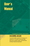
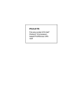
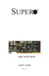
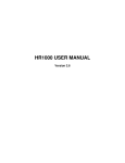
MIC-3640
Ultra2 Wide SCSI Card for
CompactPCI ®
Preface and Table of Contents
Copyright Notice
This document is copyrighted, 1999. All rights are reserved. The
original manufacturer reserves the right to make improvements to the
products described in this manual at any time without notice.
No part of this manual may be reproduced, copied, translated or
transmitted in any form or by any means without the prior written
permission of the original manufacturer. Information provided in this
manual is intended to be accurate and reliable. However, the original
manufacturer assumes no responsibility for its use, nor for any
infringements upon the rights of third parties which may result from its
use.
Acknowledgments
IBM, OS/2 are trademarks of International Business Machines Corporation.
Intel, Pentium, are trademarks of Intel Corporation.
Windows is a registered trademark of Microsoft Corporation.
Symbios is a trademark of Symbios Logic Corporation.
Netware is a trademark of Novell, Inc.
PICMG™, CompactPCI™ and the PICMG™, and CompactPCI™ logos
are trademarks of the PCI Industrial Computers Manufacturers Group.
All other product names or trademarks are properties of their
respective owners.
CE Notification
The MIC-3640, developed by Advantech CO., LTD., has passed the CE
test for environment specification when shielded cable are used for
external wiring. We recommend the use of shielded cables.
Part No. 2003364000
Printed in Taiwan
MIC-3640 User's Manual
1st Edition
July 1999
Product warranty
Advantech warrants to you, the original purchaser, that each of its
products will be free from defects in materials and workmanship for
one year from the date of purchase.
This warranty does not apply to any products which have been
repaired or altered by persons other than repair personnel authorized
by Advantech, or which have been subject to misuse, abuse, accident
or improper installation. Advantech assumes no liability under the
terms of this warranty as a consequence of such events.
Because of Advantech’s high quality-control standards and rigorous
testing, most of our customers never need to use our repair service. If
an Advantech product is defective, it will be repaired or replaced at no
charge during the warranty period. For out-of-warranty repairs, you
will be billed according to the cost of replacement materials, service
time and freight. Please consult your dealer for more details.
If you think you have a defective product, follow these steps:
1. Collect all the information about the problem encountered. (For
example, CPU speed, Advantech products used, other hardware
and software used, etc.) Note anything abnormal and list any onscreen messages you get when the problem occurs.
2. Call your dealer and describe the problem. Please have your
manual, product, and any helpful information readily available.
3. If your product is diagnosed as defective, obtain an RMA (return
merchandize authorization) number from your dealer. This allows us
to process your return more quickly.
4. Carefully pack the defective product, a fully-completed Repair and
Replacement Order Card and a photocopy proof of purchase date
(such as your sales receipt) in a shippable container. A product
returned without proof of the purchase date is not eligible for
warranty service.
5. Write the RMA number visibly on the outside of the package and
ship it prepaid to your dealer.
Preface and Table of Contents
Packing List
Before installing your board, ensure that the following materials have
been received:
• 1 MIC-3640 CompactPCI SCSI card
• 1 utility CD-ROM disc
• 1 warranty certificate
• This user's manual
If any of these items are missing or damaged, contact your distributor
or sales representative immediately.
Technical Support and Sales Assistance
If you have any technical questions about the MIC-3640 or any other
Advantech products, please visit our support website at:
• http://support.advantech.com.tw
For more information about Advantech's products and sales information, please visit:
• http://www.advantech.com
MIC-3640 User's Manual
Contents
Chapter 1: Introduction .............................................................. 1
1.1 Description ........................................................................................... 2
1.2 Specifications ........................................................................................ 2
1.3 Safety Precautions ................................................................................ 3
Chapter 2: Hardware and Drivers Installation ............................ 5
2.1 Initial Inspection ................................................................................... 6
2.2 Board Layout: Dimensions ................................................................... 7
2.3 Board Layout: Connector Locations ..................................................... 8
2.4 Front Panel Connectors and Indicators .............................................. 10
2.5 Card Installation .................................................................................. 11
2.6 Utility User's Guide and Installation Instructions ............................... 12
2.7 Building Driver Diskettes .................................................................... 14
2.8 Driver and Utility Installation .............................................................. 15
Appendix A: Pin Assignments ................................................. 17
A.1 Internal 50-pin SCSI Connector (CN1) ............................................... 18
A.2 External 68-pin SCSI Connector (CN2) ............................................... 19
A.3 Internal 68-pin SCSI Connector (CN3) ............................................... 21
A.4 J1 connector pin assignments ........................................................... 23
Figures
Figure 2-1: MIC-3640 board layout: Dimensions ........................................ 7
Figure 2-2: MIC-3640 board layout: Connector locations ........................... 8
Figure 2-3: MIC-3640 front panel connectors and locations .................... 10
Preface and Table of Contents
Tables
Table 2-1: MIC-3640 connectors ................................................................. 9
MIC-3640 User's Manual
CHAPTER
Introduction
1
1.1
Description
The MIC-3640 is a 3U-sized high-speed SCSI card for CompactPCI
systems, which is compliant with CompactPCI specification 2.0 R2.1.
The MIC-3640 uses the Symbios SYM53C895 SCSI processor to
provide an Ultra2 wide SCSI interface with data transfer rate up to 80
MB/s. It can support cables up to 12-meters long and up to 16 LVD
devices on a wide LVD ( Low Voltage Differential) SCSI bus. The MIC3640 comes with drivers in the utility CD-ROM disc for a variety of
operating systems, including DOS, Windows 3.1, Windows 98/95/NT,
OS/2, SCO UNIX, UnixWare, and NetWare.
1.2
Specifications
• Controller: Symbios SYM53C895
• Supports 16-bit Low Voltage Differential (LVD) and Single Ended
(SE) signaling
• Performs Ultra2 wide SCSI LVD synchronous, transfers as fast as 80
MB/s
• Board size: 160 x 100 mm (6.3"x3.9"), 1-slot (4TE) wide
• Weight: 0.2 kg
• Power consumption: +5V @ 2.0 A (max.)
• Operating temperature: 0 ~ 70° C (32 ~ 158° F)
• Storage temperature: -20° C ~ 80° C(-4 ~ 176° F)
• Humidity (operating and storage): 5 ~ 95% (non-condensing)
2
MIC-3640 User's Manual
1.3 Safety Precautions
Follow these simple precautions to protect yourself from harm and the
products from damage.
1. To avoid electric shock, always disconnect the power from your PC
chassis before you work on it. Don't touch any components on the
CPU card or other cards while the PC is on.
2. Disconnect power before making any configuration changes. The
sudden rush of power as you connect a jumper or install a card may
damage sensitive electronic components.
3. Always ground yourself to remove any static charge before you
touch your CPU card. Be particularly careful not to touch the chip
connectors. Modern integrated electronic devices, especially CPUs
and memory chips, are extremely sensitive to static electric discharges and fields. Keep the card in its antistatic packaging when it
is not installed in the PC, and place it on a static dissipative mat
when you are working with it. Wear a grounding wrist strap for
continuous protection.
Chapter 1 Introduction
3
4
MIC-3640 User's Manual
CHAPTER
2
Hardware and Drivers
Installation
2.1 Initial Inspection
We carefully inspected the MIC-3640 mechanically and electronically
before shipping. It should be free of marks and scratches and in
perfect working order on receipt.
As users unpack the MIC-3640, check it for signs of shipping damage
(damaged box, scratches, dents, etc.). If it is damaged or fails to meet
specifications, notify Advantech's service department or the local
sales representative immediately. Also notify the carrier that was used
to ship the product to user's location from Advantech's factory or
distributor. Retain the shipping carton and packing material for
inspection by the carrier. Advantech will make arrangements to repair
or replace the unit after an inspection.
Warning: Discharge your body's static electric charge by
touching the back of the grounded chassis of the
system unit (metal) before handling the board. You
should avoid contact with materials that hold a static
charge such as plastic, vinyl and styrofoam. Touch
the board only by its edges to avoid static damage to
its integrated circuits. Avoid touching the exposed
circuit connectors.
6
MIC-3640 User's Manual
2.2
Board Layout: Dimensions
160 mm
100 mm
Figure 2-1: MIC-3640 board layout: Dimensions
Chapter 2 Hardware and Drivers Installation
7
2.3
Board Layout: Connector Locations
CN1 Int. 50-pin SCSI
PWR LED (UP)
ACT LED (DOWN)
CN2 Ext.
68 pin SCSI
CN3 Int. 68 pin SCSI
Figure 2-2: MIC-3640 board layout: Connector locations
8
MIC-3640 User's Manual
Table 2-1: MIC-3640 connectors
Number
Function
CN1
Internal 50-pin SCSI connector
CN2
External 68-pin SCSI connector
CN3
Internal 68-pin SCSI connector
PWR LED
Power LED,
ACT LED
SCSI Activity LED
The internal 50-pin SCSI connector (CN1) is an internal interface
supporting Fast, Ultra, and Ultra Wide SCSI mode where the data
transfer rate is 10, 20, and 40 MB/s respectively. The external 68-pin
SCSI connector (CN2) and the internal 68-pin SCSI connector (CN3)
both are Ultra2 wide SCSI interfaces whose data transfer rate can be up
to 80 MB/s. These two connectors are basically identical while the
external connector is for external cabling and the internal connector is
for internal (on-board) cabling. It is not recommended to connect both
the internal 50-pin SCSI connector (CN1) and the external 68-pin SCSI
(CN2)/internal 68-pin SCSI (CN3) connector at the same time because
the data transfer rate at the external 68-pin SCSI (CN2)/internal 68-pin
SCSI connector (CN3) will be down to 40 MB/s or lower due to the
lower transfer rate of the internal 50-pin SCSI connector (CN1). Please
do not connect these three connectors at the same time. The symbios
SYM53C895 chip dose not support this kind of commection and may
cause damage to the board.
Chapter 2 Hardware and Drivers Installation
9
2.4
Front Panel Connectors and Indicators
®
ACT
PWR
SCSI
Figure 2-3: MIC-3640 front panel connectors and locations
10
MIC-3640 User's Manual
2.5
Card Installation
The MIC-3640 is a PCI bus master card. It can be installed only in a
CompactPCI slot which supports bus master function. Some processor boards do not support bus master for each slot. Please refer to the
user's manual of the processor board in use.
The CompactPCI connectors are firm and rigid and require careful
handling while plugging and unplugging. Improper installation of a
card can easily damage the backplane of the chassis.
The insert/eject handle of the MIC-3640 helps you to install and
remove the card easily and safely. Follow the procedure below to
install the MIC-3640 into a chassis:
To install a card:
1. Hold the card vertically. Be sure that the card is pointing in the
correct direction. The components of the card should be pointing
to the right-hand side.
2. Holding the lower handle, pull out the red portion in the middle of
the handle to unlock it.
Caution:
Keep your fingers away from the hinge to prevent your
fingers from getting pinched.
3. Insert the card into the chassis by sliding the upper and lower
edges of the card into the card guide.
4. Push the card into the slot gently by sliding the card along the card
guide until the handles meet the rectangular holes of the cross rails.
Note:
If the card is correctly positioned and has been slid
all the way into the chassis, the handle should match
the rectangular holes. If not, remove the card from
the card guide and repeat step 3 again. Do not try to
install a card by forcing it into the chassis.
5. Lift the lower handle up to push the card into place.
6. Secure the card by pushing in the red handle to lock it into place.
Chapter 2 Hardware and Drivers Installation
11
To remove a card:
1. Unscrew the four screws on the front panel. Pull out the red
position in the middle of the handle to unlock the handle.
2. Press the lower handle down to release the card from the backplane.
3. Slide the card out.
2.6
Utility User's Guide and Installation
Instructions
The utility user's guide and installation instructions are provided in
.htm format in the utility CD-ROM disc. Users can browse the instructions using a Java-aware browser such as Microsoft Internet Explorer
v3.0 or later, or Netscape 2.0 or later. To utilize the full functionality of
the CD, Microsoft Internet Explorer is recommended. Netscape will
work, but links that launch applications are disabled in Netscape.
The instructions are located in the directory \SYM895\HTML and
include:
For DOS:
• ASPI8XX.HTM: Installation guide for ASPI manager
• DOS.HTM: Device drivers for DOS/Windows 3.x
• DOSCONF.HTM: SDMS DOS configuration utility
• SYMCD.HTM: CDROM support using the ASPI manager.
• SYMDISK.HTM: Device driver that provides support for nonINT13h SCSI disk drives and removable media devices using the
ASPI manager.
• VERIFY.HTM: SDMS DOS verify utility user's guide
For Windows 95/98:
• DEVMGR95.HTM: Installing the SYMC8XX.MPD/SYM_HI.MPD
driver in Windows 95
• SCSITOOL.HTM: Installation guide for Symbios SCSI tools for
Windows 95/98 and Windows NT
12
MIC-3640 User's Manual
• WIN95.HTM: Installation guide for device drivers for Windows 95
and Windows 98
For Windows NT:
• WINNT.HTM: Installation guide for device drivers for Windows NT
• NEWASNT.HTM: Windows NT 4.0 guided installation for installing
SYMC8XX or SYM_HI drivers
• NTCONFG.HTM: Windows NT configuration utility (NTCONFIG)
• NTDMI.HTM: Installation guide for NT DMI 1.0 component
instrumentation
• NTDMI2.HTM: Installation guide for NT DMI 2.0 component
instrumentation
• SCSITOOL.HTM: Installation guide for Symbios SCSI tools for
Windows 95/98 and Windows NT
For SCO Unix:
• BLDBTLD.HTM: Building the SCO UnixWare BTLD diskette
• BUILDSCO.HTM: Building the SCO OpenServer BTLD diskette
• SCOUNIX.HTM: Installation guide for the Symbios SDMS SCO
UNIX driver
• UNIXWARE.HTM: Installallation guide for the Symbios SDMS
UnixWare driver
For NetWare:
• NETWDMI.HTM: NetWare DMI 1.0 SDMS component instrumentation
• NWPA.HTM: Installation guide for Symbios NetWare NWPA
drivers SYM8XXNW.HAM and SYMHINW.HAM
For OS/2:
• OS2.HTM: Driver installation for OS/2
Chapter 2 Hardware and Drivers Installation
13
For Solaris:
• SOLARIS.HTM: Installation guide for the Solaris device driver
Other tools and utilities
• BIOS.HTM: User's guide for SCSI BIOS configuration utility
• FLASH.HTM: SDMS host adapter flash utility
• FORMAT.HTM: SDMS SCSI low-level format utility
• RAWRITE.HTM: Description of RaWrite 1.3
• UTILMAIN.HTM: SDMS utilities user's guides
2.7 Building Driver Diskettes
You may need to build driver diskettes for installation when the CDROM drive is not available or when the operating system does not
support installation from a CD-ROM.
Insert a 1.44 MB diskette in the floppy drive and run the programs
listed below to make driver diskettes:
• \SYM895\DISKIMAG\DOS_BIOS.EXE: DOS and SDMS SCSI BIOS
• \SYM895\DISKIMAG\SCSITOOL.EXE: SCSI tools for Windows 95
and NT
• \SYM895\DISKIMAG\8XXNT95.EXE: Drivers for Windows 95/NT
• \SYM895\DISKIMAG\NW_OS2.EXE: Drivers for NetWare and
OS/2
• \SYM895\DISKIMAG\NTCONFIG.EXE: Configuration utility for
Windows NT
• \SYM895\DISKIMAG\DOSUTILS.EXE: DOS configuration and
format utility
14
MIC-3640 User's Manual
2.8 Driver and Utility Installation
The drivers and utilities for the SCSI interface are provided in the
directories \SYM895\DRIVERS, \SYM895\UTILITY, and
\SYM895\WINNT on the utility CD-ROM disc. The path and file
names of the drivers and utilities are listed below.
For DOS and Windows 3.1:
• \SYM895\DRIVERS\DOS
For Windows 95/98:
• \SYM895\DRIVERS\WIN95
For Windows NT:
• \SYM895\DRIVERS\WINNT
• \SYM895\WINNT
For SCO Unix:
• \SYM895\DRIVERS\UNIX
For NetWare:
• \SYM895\DRIVERS\NETWARE
For OS/2:
• \SYM895\DRIVERS\OS2
For Solaris:
• \SYM895\DRIVERS\UNIX\SOLARIS
Other tools and utilities
• \SYM895\DRIVERS\BIOS
• \SYM895\UTILITY
Please refer to related documents listed in section 2.6 for detailed
installation guides.
Chapter 2 Hardware and Drivers Installation
15
16
MIC-3640 User's Manual
APPENDIX
A
Pin Assignments
A.1 Internal 50-pin SCSI Connector (CN1)
2
4
.... 48 50
1
3
.... 47 49
Table A-1: MIC-3640 Internal 50-pin SCSI connector
Pin
1
2
3
4
5
6
7
8
9
10
11
12
13
14
15
16
17
18
19
20
21
22
23
24
25
18
Signal
SD+0
SD-0
SD+1
SD-1
SD+2
SD-2
SD+3
SD-3
SD+4
SD-4
SD+5
SD-5
SD+6
SD-6
SD+7
SD-7
SDP+0
SDP-0
GND
GND
DIFS
GND
TPWEX
GND
TPWEX
MIC-3640 User's Manual
Pin
26
27
28
29
30
31
32
33
34
35
36
37
38
39
40
41
42
43
44
45
46
47
48
49
50
Signal
TPWEX
GND
GND
GND
GND
SATN+
SATNGND
GND
SBSY+
SBSYSACK+
SACKSRST+
SRSTSMSG+
SMSGSSEL+
SSELSCD+
SCDSREQ+
SREQSIO+
SIO-
A.2 External 68-pin SCSI Connector (CN2)
34 33
68 67
2
1
36 35
Table A-2: MIC-3640 External 68-pin SCSI connector
Pin
1
2
3
4
5
6
7
8
9
10
11
12
13
14
15
16
17
18
19
20
21
22
23
24
25
Signal
SD+12
SD+13
SD+14
SD+15
SDP+1
SD+0
SD+1
SD+2
SD+3
SD+4
SD+5
SD+6
SD+7
SDP+0
GND
DIFS
TPWEX
TPWEX
N/C
GND
SATN+
GND
SBSY+
SACK+
SRST+
Pin
35
36
37
38
39
40
41
42
43
44
45
46
47
48
49
50
51
52
53
54
55
56
57
58
59
Signal
SD-12
SD-13
SD-14
SD-15
SDP-1
SD-0
SD-1
SD-2
SD-3
SD-4
SD-5
SD-6
SD-7
SDP-0
GND
SENEX
TPWEX
TPWEX
N/C
GND
SATNGND
SBSYSACKSRST-
Appendix A Pin Assignments
19
26
27
28
29
30
31
32
33
34
20
SMSG+
SSEL+
SCD+
SREQ+
SIO+
SD+8
SD+9
SD+10
SD+11
MIC-3640 User's Manual
60
61
62
63
64
65
66
67
68
SMSGSSELSCDSREQSIOSD-8
SD-9
SD-10
SD-11
A.3 Internal 68-pin SCSI Connector (CN3)
34 33
68 67
1
2
36 35
Table A-3: MIC-3640 Internal 68-pin SCSI connector
Pin
1
2
3
4
5
6
7
8
9
10
11
12
13
14
15
16
17
18
19
20
21
22
23
24
25
Signal
SD+12
SD+13
SD+14
SD+15
SDP+1
SD+0
SD+1
SD+2
SD+3
SD+4
SD+5
SD+6
SD+7
SDP+0
GND
DIFS
TPWEX
TPWEX
N/C
GND
SATN+
GND
SBSY+
SACK+
SRST+
Pin
35
36
37
38
39
40
41
42
43
44
45
46
47
48
49
50
51
52
53
54
55
56
57
58
59
Signal
SD-12
SD-13
SD-14
SD-15
SDP-1
SD-0
SD-1
SD-2
SD-3
SD-4
SD-5
SD-6
SD-7
SDP-0
GND
SENIN
TPWEX
TPWEX
N/C
GND
SATNGND
SBSYSACKSRST-
Appendix A Pin Assignments
21
26
27
28
29
30
31
32
33
34
22
SMSG+
SSEL+
SCD+
SREQ+
SIO+
SD+8
SD+9
SD+10
SD+11
MIC-3640 User's Manual
60
61
62
63
64
65
66
67
68
SMSGSSELSCDSREQSIOSD-8
SD-9
SD-10
SD-11
A.4 J1 connector pin assignments
Table A-4: J1 connector pin assignments
Pin
25
Row A
+5V
Row B
REQ64#
Row C
ENUM#
Row D
+3.3V
Row E
+5V
24
AD1
+5V
VI/O
AD0
ACK64#
23
+3.3V
AD4
AD3
+5V
AD2
22
AD7
GND
+3.3V
AD6
AD5
21
+3.3V
AD9
AD8
M66EN
C/BE0#
20
AD12
GND
V I/O
AD11
AD10
19
+3.3V
AD15
AD14
GND
AD13
18
SERR#
GND
+3.3V
PAR
C/BE1#
17
+3.3V
SDONE
SBO#
GND
PERR#
16
DEVSEL#
GND
V I/O
STOP#
LOCK#
15
+3.3V
FRAME#
IRDY#
GND
TRDY#
14
13
KEY
AREA
12
11
AD18
AD17
AD16
GND
C/BE2#
10
AD21
GND
+3.3V
AD20
AD19
9
C/BE3#
IDSEL
AD23
GND
AD22
8
AD26
GND
V I/O
AD25
AD24
7
AD30
AD29
AD28
GND
AD27
6
REQ#
GND
+3.3V
CLK
AD31
5
BRSVA5
BRSVB5
RST#
GND
GNT#
4
BRSVA4
GND
V I/O
INTP
INTS
3
INTA#
INTB#
INTC#
+5V
INTD#
2
TCK
+5V
TMS
TDO
TDI
1
+5V
-12V
TRST#
+12V
+5V
#: low active
Appendix A Pin Assignments
23