1
PCL-833
3-axis quadrature encoder
and counter card
Copyright
This documentation and the software routines contained in the PCL833 software disk are copyrighted 1994 by Advantech Co., Ltd. All
rights are reserved. Advantech Co., Ltd. reserves the right to make
improvements in the products described in this manual at any time
without notice.
No part of this manual may be reproduced, copied, translated or
transmitted in any form or by any means without the prior written
permission of Advantech Co., Ltd. Information provided in this
manual is intended to be accurate and reliable. However, Advantech
Co., Ltd. assumes no responsibility for its use, nor for any infringements of the rights of third parties which may result from its use.
Acknowledgments
PC-LabCard is a trademark of Advantech Co., Ltd. IBM and PC are
trademarks of International Business Machines Corporation. MSDOS, Microsoft C and Quick Basic are trademarks of Microsoft
Corporation. BASIC is a trademark of Dartmouth College. Intel is a
trademark of Intel Corporation. Turbo C is a trademark of Borland
International.
Part No. 2005833000 1st Edition
Printed in Taiwan June 1994
Contents
Chapter 1
General information ....................................... 1
Introduction ........................................................................... 2
Encoder interface ...........................................................................2
Counters .........................................................................................2
Digital input and interrupts ............................................................2
Features .................................................................................. 3
Applications ........................................................................... 3
Specifications ......................................................................... 4
Encoder input .................................................................................4
Digital input ...................................................................................4
Programmable interrupt controller ................................................4
General ...........................................................................................4
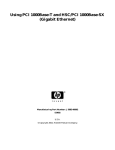
Block diagram ....................................................................... 5
Chapter 2
Installation ....................................................... 7
Initial inspection.................................................................... 8
Switch and jumper settings .................................................. 8
Base I/O address (SW1) .................................................................8
Interrupt level (JP1) .......................................................................9
Connector pin assignments ................................................ 11
Connector wiring .........................................................................12
Hardware installation ......................................................... 13
Software installation ........................................................... 14
Chapter 3
Operation ....................................................... 1 5
Quadrature encoder introduction ..................................... 16
Counter modes .................................................................... 17
Digital noise filter ................................................................ 18
Latch mode .......................................................................... 19
Counter reset value ............................................................. 20
Reset after latch .................................................................. 20
Cascade mode ...................................................................... 20
Timer function ..................................................................... 21
Interrupt function ............................................................... 22
Chapter 4
Programming ................................................ 2 3
Driver programs .................................................................. 24
Basic program structure ..................................................... 24
Driver functions .................................................................. 25
Write functions ............................................................................25
Read functions .............................................................................28
Compiling and linking with C compilers .......................... 28
Borland C .....................................................................................28
Microsoft C ..................................................................................29
Chapter 5
Register structure and format ................... 3 1
Register format (read) ........................................................ 32
Register format (write) ....................................................... 34
Appendix A
8259A Data Sheet ....................................... 3 9
CHAPTER
General
1
information
Chapter 1 General information 1
Introduction
The PCL-833 is a 3-axis quadrature encoder and counter add-on card
for the IBM PC/AT and compatibles (ISA bus). This card lets your PC
perform position monitoring for motion control systems. It provides
three 24-bit up/down counters as quadrature encoders and a 16-MHz
oscillator timebase with wide-range multiplier. An on-board interrupt
controller handles nine different interrupt sources.
Encoder
interface
Each input includes a decoding circuit for incremental quadrature
encoding. Inputs accept either single-ended or differential signals.
Quadrature input works with or without an index, allowing linear or
rotary encoder feedback.
Counters
The PCL-833 has three independent 24-bit counters. The maximum
quadrature input rate is 1.0 MHz, while the maximum input rate in
counter mode is 2.4 MHz. You can individually configure each
counter for quadrature decoding, pulse/direction counting or up/down
counting.
Digital input and interrupts
The PCL-833 provides five digital input channels. The channels
accept digital input as an index input for a rotary encoder or as a home
sensor input for a linear encoder.
The card can generate an interrupt to the system based on a signal
from its digital inputs, overflow/underflow of its counters or on a
programmed time interval. It can repeatedly generate interrupts at any
time interval you specify, 0.1 msec to 255 sec. These interrupts let you
precisely monitor the speed of a control system.
2
PCL-833 User's Manual
Features
• Three 24-bit up/down counters (cascade for up to 48 bits)
• 1.0 MHz max quadrature input rate
• 2.4 MHz max. input pulse rate
• Single ended or differential inputs
• Pulse/direction and up/down counter
• X1, X2, X4 counts for each encoder cycle
• Optically isolated up to 2500 V
• 4-stage digital filter with selectable sampling rate
• 16-MHz oscillator timebase with wide-range multiplier
• On-board interrupt controller with nine different interrupt sources
• Digital input with interrupt for each axis
• Programmable time interval interrupt
• Half-size AT-bus card
Applications
• Motion control
• Position sensing, monitoring and measuring
• Coordinate measuring machines
• X-Y table monitors
• Robotics
• Machine control
Chapter 1 General information 3
Specifications
Encoder
input
• No. of Axes: Three independent axes
• Max. quadrature input freq.: 1.0 MHz
• Max. input pulse freq.: 2.4 MHz
• Counts per encoder cycle: 1, 2 or 4 (s/w selectable)
• Encoder type: Single-ended or differential
• Counter size: 24 bits, easily daisychains for up to 48 bits
• Counter modes:
Quadrature, up/down, count/direction (s/w selectable)
• Digital filter: 4 stage
• Sample clock freq.: 8, 4 or 2 MHz (s/w selectable)
• Input isolation: 2500 VRMS using optical isolators
Digital input
• No. of channels: five differential, with interrupt
• Input isolation: 2500 VRMS using optical isolators
Programmable
interrupt
controller
10-Hz, 1-KHz or 10-KHz time base (s/w selected) with a programmable multiplier from 1 to 255
General
• Connector: DB-25
• Board dimensions: 185 mm x 100 mm
4
PCL-833 User's Manual
diagram
24-BIT
UP/DOWN
COUNTER
COUNTER
MODE
CONTROL
DIGITAL
FILTER
CONTROL AND DATA BUS
24-BIT MUTI-MODE
UP/DOWN COUNTER
24-BIT MUTI-MODE
UP/DOWN COUNTER
DIFF/SE ISOLATION INPUT CIRCUIT
Block
CH.1 PHASE A
CH.1 PHASE B
CH.1 INDEX
CH.2 PHASE A
CH.2 PHASE B
CH.2 INDEX
CH.3 PHASE A
CH.3 PHASE B
CH.3 INDEX
D/I CH. 0
D/I CH. 1
CONTROL UNIT
INTERRUPT
CONTROLLER
ADDRESS
DECODER
PROGRAMMABLE
TIME-BASE
GENERATOR
ADDRESS, DATA AND CONTROL BUS BUFFER
PC BUS
Chapter 1 General information 5
6
PCL-833 User's Manual
CHAPTER
2
Installation
Chapter 2 Installation
7
Initial
inspection
In addition to this manual the shipping container should contain the
PCL-833 card and a utility diskette. We carefully inspected the PCL833 mechanically and electrically before we shipped it. It should be
free of marks and scratches and in perfect electrical order on receipt.
As you unpack the card, check it for signs of shipping damage
(damaged box, scratches, dents, etc.). If it is damaged or fails to meet
its specifications, notify our service department or your local sales
representative immediately. You will need to contact the carrier so that
it can inspect the shipping carton and packing material. We will then
arrange to repair or replace the unit.
Remove the PCL-833 interface card from its protective packaging
carefully. Keep the antistatic package. Whenever you are not using the
board, please store it in the packaging for protection.
Warning! Discharge any static electric charge on your body by
touching grounded metal before you handle the
board. You should avoid contact with materials that
create static electricity such as plastic, vinyl, and
styrofoam. Handle the board by its edges to avoid
contacting the board's integrated circuits.
Switch
and
jumper
settings
DIP switch SW1 sets the card's I/O address and jumper JP1 sets the
card's interrupt level.
Base I/O address (SW1)
The PCL-833 requires 16 consecutive I/O addresses. DIP switch SW1
(shown below) sets the base I/O address.
ON
1
8
PCL-833 User's Manual
2
3
4
5
6
Choose a base address that is not in use by any other I/O device. A
conflict with another device may cause one or both devices to fail.
The factory address setting (hex 200) is usually free as it is reserved
for PC prototype boards.
Jumper settings for various base addresses appear below:
Card I/O addresses (SW1)
Range (hex)
Switch position
1
2
3
4
5
6
* 200 - 20F
l
¡
¡
¡
¡
¡
210 - 21F
l
¡
¡
¡
¡
l
220 - 22F
l
¡
¡
¡
l
¡
230 - 23F
l
¡
¡
¡
l
l
240 - 24F
l
¡
¡
l
¡
¡
l
l
l
l
l
l
×
3F0 - 3FF
¡ = On
Note:
l = Off
* = default
Switches 1-6 control the PC bus address lines as follows:
Switch
Line
1
A9
2
A8
3
A7
4
A6
5
A5
6
A4
Interrupt level (JP1)
The jumper JP1 selects the card's interrupt level (2, 4, 5, 7, 10, 11, 12
15), as shown below:
Card interrupt (default = 7)
IRQ
15 12 11 10 7
5
4
2
¡ ¡ ¡ ¡ ¡ ¡ ¡ ¡
¡ ¡ ¡ ¡ ¡ ¡ ¡ ¡
Do not select a level that is being used by another device unless you
have performed special programming to share several devices on one
interrupt.
Chapter 2 Installation
9
To use the interrupt you must install an interrupt service routine and
program the PCL-833's on-board the 8259 interrupt controller.
Nine different conditions can enable the PCL-833's interrupt, but only
one at a time.
Interrupt source
0
Condition
CH1 overflow
1
CH2 overflow
2
CH3 overflow
3
CH1 ZIN
4
CH2 ZIN
5
CH3 ZIN
6
DI0
7
Shared by TIMER and DI1
Bit 3 of register BASE+9 switches interrupt source 7 between the
card's TIMER and DI1. See Chapter 3 for details.
You should treat all the interrupt sources as positive-edge triggered
when you program the 8259.
10
PCL-833 User's Manual
Connector
pin
assignments
You make all connections to the PCL-833 through a single DB-25
connector, shown below:
EGND
CH1A+
CH1B+
CH1Z+
CH2A+
CH2B+
CH2Z+
CH3A+
CH3B+
CH3Z+
CDI0+
CDI1+
EGND
1
2
14
15
3
4
5
16
17
18
6
19
7
20
8
9
10
21
22
23
11
12
13
24
25
CH1ACH1BCH1ZCH2ACH2BCH2ZCH3ACH3BCH3ZCDI0CDI1EVCC
Connector pin assignments appear below:
Pin
EGND
Function
External ground
EVCC
External Vcc, DC 5V ± 0.25 V
CH1A-
Channel 1 A differential negative- input
CH1A+
Channel 1 A differential positive - input
CH1B-
Channel 1 B differential negative - input
CH1B+
Channel 1 B differential positive - input
CH1Z-
Channel 1 Z differential negative - input
CH1Z+
Channel 1 Z differential positive - input
CH2A-
Channel 2 A differential negative- input
CH2A+
Channel 2 A differential positive - input
Chapter 2 Installation
11
Pin
CH2B-
Function
Channel 2 B differential negative - input
CH2B+
Channel 2 B differential positive - input
CH2Z-
Channel 2 Z differential negative - input
CH2Z+
Channel 2 Z differential positive - input
CH3A-
Channel 3 A differential negative - input
CH3A+
Channel 3 A differential positive - input
CH3B-
Channel 3 B differential negative - input
CH3B+
Channel 3 B differential positive - input
CH3Z-
Channel 3 Z differential negative - input
CH3Z+
Channel 3 Z differential positive - input
CDI0-
Digital input No. 0 differential negative - input
CDI0+
Digital input No. 0 differential positive - input
CDI1-
Digital input No. 1 differential negative - input
CDI1+
Digital input No. 1 differential positive - input
Connector
wiring
External/internal
power
If you use an external power supply, connect pins 1 and 13 to external
ground and connect pin 25 to external VCC.
If you use the card's internal power supply, place 0-Ω resistors
(jumper wires) at locations L1 and L2 on board (see labels printed on
board).
Differential/single-ended
input
With differential inputs connect the negative wire to the negative pin
and the positive wire to the positive pin. For example, with channel 3
A connect the negative input wire to CH3A- and the positive wire to
CH3A+.
With single-ended inputs connect the input to the positive pin and
leave the negative pin open.
AB phase encoder
In 2-pulse input mode A inputs (CH1A, CH2A, etc.) count up while
their corresponding B inputs (CH1B, CH2B) count down.
12
PCL-833 User's Manual
In 1-pulse input mode A inputs (CH1A, etc.) count up or down and B
inputs (CH1B, etc.) determine the direction to count. A logical high
(1) on the B channel indicates that the pulse on the A channel is an up
count, and a logical low (0) indicates that the pulse is a down count.
Hardware
installation
Warning! Disconnect power from your PC whenever you
install or remove the PCL-833 or its cables
Installing the card in your computer:
1. Turn off the computer and all peripheral devices (such as printers
and monitors).
2. Disconnect the power cord and any other cables from the back of
the computer. Turn the chassis so the back of the unit faces you.
3. Remove the chassis cover (see your computer users guide if
necessary).
4. Locate the expansion slots at the rear of the unit and choose an
unused slot.
5. Remove the screw that secures the expansion slot cover to the
chassis. Save the screw to secure the PCL-833.
6. Carefully grasp the upper edge of the PCL-833 card. Align the
hole in the retaining bracket with the hole on top of the expansion
slot, and align the gold striped edge connector with the expansion
slot socket. Press the board firmly into the socket.
7. Replace the screw in the expansion slot retaining bracket.
8. Attach necessary accessories to the card.
9. Replace the chassis cover. Connect the cables you removed in step
2. Turn on the computer.
Hardware installation is now complete. You can now install the
software driver as described in the next section.
Chapter 2 Installation
13
Software
installation
The utility diskette included with the PCL-833 holds a test utility
program, example programs and driver programs. We supply the
driver as C source code for Borland and Microsoft compilers. To use
the driver you compile it along with your program.
See Chapter 4 for more information.
The following table describes the contents of the disk.
Program
833test.exe
Description
Tests most of the PCL-833's functions
833demo1.c
Example program which uses the PCL-833 driver to
perform A B phase encoding on 3 channels
833demo2.c
Example program which performs 2-pulse encoding on
a 48-bit counter (Channel 1 cascades into Channel 2)
833demo3.c
Example program which shows how to use card's
interrupt functions
833tc.c
Software driver program for Borland Turbo C and
Borland C compilers
833mc.c
Software driver program for Microsoft C compilers
Make a working copy of the master disk and store the master disk in a
safe place. You can use COPY or DISKCOPY to copy the disk files to
another floppy disk or use COPY to copy the files to a hard disk.
14
PCL-833 User's Manual
CHAPTER
3
Operation
Chapter 3 Operation 15
Quadrature
encoder
introduction
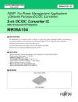
In typical closed-loop control systems, also know as servo systems,
the encoder interface senses motor position and sends a position signal
to the controller. The diagram below shows a typical servo system.
The encoder generates pulses which indicate the shaft position. The
encoder output includes two signals, commonly called channel A and
channel B, which generate N pulses per revolution. The two signals
are shifted by a quarter of a cycle, as shown below. The shift between
the two signals enables the controller to determine the direction of
rotation, depending on whether channel A leads channel B or vice
versa.
MICROCOMPUTER
BUS
QUADRATURE
SIGNAL
PHASE A
PHASE B
HOST
CPU
INDEX
PCL-833
ENCODER
CARD
QUADRATURE
ENCODER
(MOTER)
QUADRATURE
SIGNAL
16
PCL-833 User's Manual
Single-ended
vs.
differential
input
Most encoders produce square wave signals with TTL levels. Industrial systems often use encoders with differential signals, i. e. channel A
and B and their complements. Differential signals can reduce sensitivity to noise and allow longer transmission distances. Encoders may
also produce a third signal once per revolution known as the index or
marker. The encoder interface can use the index signal to reset the
counter, allowing you to monitor the position within the current
revolution.
Counter
modes
The following table shows the maximum input rate for each input
mode and system clock rate. Values are given for each system clock
frequency.
Mode
Quadrature X1, X2, X4
8 MHz
1 MHz
Maximum input rate
4 MHz
2 MHz
600 KHz
300 KHz
2-pulse
2.4 MHz
1.2 MHz
600 KHz
Pulse/direction
2.4 MHz
1.2 MHz
600 KHz
Counter modes are as follows:
Quadrature
input
counter
mode
Quadrature input consists of two square wave inputs (A and B) which
are 90o out of phase. The PCL-833 counts the square wave transitions
and determines the direction by comparing whether channel A is
leading channel B or vice versa.
There are three different counting methods in quadrature input mode:
X1
The counter will increment (or decrement) the counter whenever a rising edge occurs on input channel A.
X2
The counter will increment (or decrement) whenever a rising or
falling edge occurs on input channel A.
X4
The counter will increment (or decrement) whenever a rising or
falling edge occurs on input channel A or B.
Chapter 3 Operation 17
2-pulse
mode
In 2-pulse mode the PCL-833 uses two input pulses as counting
sources: one for clockwise (CW) and one for counterclockwise
(CCW) counting. The counter will decrement whenever a rising edge
occurs on channel A. It will increment whenever a rising edge occurs
on channel B.
Pulse/direction
mode
In pulse/direction mode the PCL-833 uses one input line (A) for pulse
input and one line (B) for direction. If channel B is high (1), the
counter will decrement whenever a rising edge occurs on channel A. If
channel B is low (0), the counter will increment whenever a rising
edge occurs on channel A.
Disabled
mode
PCL-833 will not accept input, but you can still access all its registers.
You select the mode by programming the card's registers: BASE+0 for
CH1, BASE+1 for CH2 and BASE+2 for CH3. See Chapter 5 for
more information.
Digital noise filter
Noise immunity is the most important requirement for reliable
encoder interface operation. The PCL-833 conditions the input signals
with a four stage digital filter. This filter reduces glitches (digital
noise) or spikes by sampling the input at 2, 4 or 8 MHz. The filter
output waveforms change only when an input has the same value for
three consecutive sampling edges. The filter thus rejects noise or
pulses shorter than two sampling clock periods. You can optimize
noise immunity by selecting the lowest sampling frequency that
compatible with the highest input rate you expect.
The PCL-833 accepts up to 1 MHz quadrature freq. at 8 MHz filter
sampling speed. At 2 MHz sampling speed it can still accept up to 300
KHz quadrature input freq.
A 3600 rpm motor with 2000 ppr encoder will have a max. quadrature
freq. of 3600 x 2000 ÷ 60 = 120 KHz. In the above example the 2
MHz sampling clock will have the best noise immunity and will meet
the required input freq.
18
PCL-833 User's Manual
The following table shows the maximum noise pulse width that the
filter will reject for each system clock frequency:
Clock freq.
8 MHz
Maximum width
375 nsec.
4 MHz
750 nsec.
2 MHz
1.5 msec.
Latch
mode
When you read a counter, you are actually reading a value latched into
a buffer. The PCL-833 provides five different latching modes, only
one of which is active at any given time. Make sure that you know
which latching mode is current whenever you read the counter.
Otherwise, you may read an old value or one that was latched at a
different time than you expect.
You select the latching mode for each channel individually. That is,
you might select S/W latching on channel 1 and DIO latching for
channels 2 and 3. Bits 0-2 of register BASE+3 control CH1, BASE+4
control CH2 and BASE+5 control CH3. See Chapter 5 for more
information.
The PCL-833's latching modes are as follows:
S/W latch
Whenever you read a channel's data registers, the counter values will
be latched in buffer. The S/W latch will only take effect when you
read the high byte of the counter (C23-C16). Reading middle byte or
low byte of a counter won’t latch the counter values to the buffer. You
should therefore read the high byte first, then the other two bytes of
the counter.
Index latch
A rising edge on the channel's index input line will latch the channel's
counter value.
DI0 latch
A rising edge on the board's DI0 line will latch the counter value for
the channel.
Chapter 3 Operation 19
DI1 latch
A rising edge on the DI1 line will latch the counter value for the
channel.
Timer
latch
The card latches the counter value on a rising edge of pulses from the
card's on-board timer.
Counter reset value
Bit 3 (RF) of registers BASE+0, 1 and 2 control the initial (reset)
value of for each counter. You can select either 000000 or 800000
(hex). When the counter is reset, it will take this value.
When RF = 0, the counter will reset to 000000h.
When RF = 1, the counter will reset to 800000h.
Reset after latch
Bit 3 (LC) of registers BASE+3, 4 and 5 determine whether the
corresponding counter will reset to its initial value (see preceding
section) when it is latched.
If LC = 1, the counter will reset to its initial value when it is latched.
If LC = 0, the counter will stay the same (keep its previous value)
when it is latched.
Cascade
mode
24 bits is enough for most counter applications. If you need to store
larger values, you can cascade the output of one counter into the input
of a second, giving 48 bits of storage. When the first counter overflows, the card increments the second counter.
The PCL-833 lets you cascade channel 1 into channel 2 to form a
single 48-bit counter. (Channel 3 will not cascade.)
20
PCL-833 User's Manual
The mode settings of channel 1 control this 48-bit counter, except that
the setting of channel 2 controls the initial (reset) value.
You set up the 48-bit counter as follows:
1. Set bits CAS1 and CAS0 of write register BASE+8 to 01h.
2. Set CH2 to cascade mode. (Set Bits 0-2 of register BASE+1
to "1 1 1".
3. Set the initial (reset) value in CH2.
4. Set remaining modes in CH1.
To read the total value, you must read both counters. Channel 1 holds
the high 24-bits and channel 2 the low 24-bits.
Timer
function
The PCL-833's on-board timer lets you monitor counter readings with
extreme accuracy. The programmable timer generate pulses at regular
intervals. The card can latch the readings in its counters and generate
an interrupt to the PC.
You can set timer cycle periods from 1 msec. to 255 seconds. The
cycle time is the product of the timer base period and a multiplier.
Timer base periods are 1, 10, 100 or 1000 msec. The multiplier ranges
from 1 to 255. The divider can range from 1 to 255.
For example, to set a timer period of 20 msec, you would set the timer
base to 1 msec and the multiplier to 20. That is:
Timer period = Base period x multiplier
20 msec = 1 msec x 20
Set the timer period by programming registers BASE+9 and
BASE+10.
You can use the timer to latch the counter values and/or to generate an
interrupt to the PC. To use the timer latching set registers BASE+3, 4
and 5. To generate an interrupt with the timer set bit 3 of BASE+9 and
program the card's 8259A interrupt controller. See the following
sections for more information.
Chapter 3 Operation 21
Interrupt
function
The PCL-833 can generate an interrupt to the PC for any of the
following conditions:
1. Counter 1 overflow
2. Counter 2 overflow
3. Counter 3 overflow
4. Counter 1 index in
5. Counter 2 index in
6. Counter 3 index in
7. DI0 input
8. DI1 input
9. Timer pulse
The card's 8259A interrupt controller chip combines these interrupts
into a single PC interrupt, set by jumper JP1. Since the 8259A only
has eight input channels, the DI1 and timer interrupts share a single
interrupt line. Bit 3 of write register BASE+9 selects DI1 or timer.
Note that you can use only one of the card's interrupt sources at a
given time, unless you specially program your interrupt service
routine to handle multiple interrupt sources.
You enable the PCL-833 interrupt functions by programming the
card's 8259 chip, accessed through the registers at BASE+12 and
BASE+13. You will need to set the chip's interrupt mask register to
exclude all but one of the interrupt lines.
Program the 8259 in 8086/8088 mode, single mode, edge-triggered
mode. In 8086/8088 mode two INTA signals are needed. The PCL833 generates the first INTA automatically. Your program generates
the second INTA by reading BASE+15. This read returns the interrupt
vector number which caused the request.
The hold time must be at least 1 usec. after a low-to-high transition of
the interrupt source to ensure that the interrupt occurs.
See Appendix A for more information.
22
PCL-833 User's Manual
CHAPTER
4
Programming
Chapter 4 Programming
23
Driver
programs
The PCL-833 software driver has predefined routines to set up and
control the card. You specify an array of values for the card's registers.
The driver modifies the registers in the proper order and sends back
the data in a second array.
To use the driver you call the driver function and specify two arguments. The first argument holds the name of the driver operation and
the second argument holds any arguments that operation needs. For
example, to reset counter channel 1 you would type:
pcl833(CounterReset, Reset_Ch1);
The driver function returns an integer value indicating the success or
failure of the operation: 0 for success, non-zero for failure.
We supply the driver as C source code for Borland and Microsoft
compilers. To use the driver you compile it along with your program
(or compile it once and link its object file later). The file 833tc.c
contains the driver code in Turbo C format, and the file 833mc.c
contains the code in Microsoft C format. The driver arguments are
constants defined in the header file 833drive.h, so you can
change their names if you like.
Basic
program
structure
The PCL-833 utility disk includes three example programs written in
Turbo C: 833demo1.c, 833demo2.c and 833demo3.c.
The following code shows the basic structure of a C application:
#include <stdio.h>
#include “833drive.h”
extern int
pcl833(int func, int option);
/* Output and input registers */
extern int
OutReg[16];
extern int
InReg[16];
extern int
Base;
:
24
PCL-833 User's Manual
void main()
{
/* Base address setting. This must match the setting
* of switch SW1. */
Base= 0x0200;
:
}
If you call a read function, the driver will put the data in the array
InReg[]. If you read the card's registers directly to get the counter
value, instead of using the driver, you must read the highest byte
first to ensure whole counter has been latched. For example, the
following C code would read the bytes of counter channel 1:
:
InReg[2] = inportb(Base+2); // highest byte
InReg[1] = inportb(Base+1); // middle byte
InReg[0] = inportb(Base+0); // low byte
:
Driver
functions
Write
functions
Function 1:
Intialize
pcl833
argument 1: Initialize833
argument 2: NA (not applicable)
Function 2:
Set input mode
argument 1: Ch1_SetInputMode
Ch2_SetInputMode
Ch3_SetInputMode
argument 2: PclDisable
x1
x2
x4
TwoPulseIn
OnePulseIn
Chapter 4 Programming
25
Function 3:
Define reset value
argument 1: Ch1_DefineResetValue
Ch2_DefineResetValue
Ch3_DefineResetValue
argument 2: start
middle
Function 4:
Set Latch Source
argument 1: Ch1_SetLatchSource
Ch2_SetLatchSource
Ch3_SetLatchSource
argument 2: SwReadLatch
IndexInLatch
DI0Latch
DI1Latch
TimerLatch
Function 5:
Reset/no reset after counter is latched
argument 1: Ch1_IfResetOnLatch
Ch2_IfResetOnLatch
Ch3_IfResetOnLatch
argument 2: ResetNo
ResetYes
Function 6:
Latch/no latch (rollover) on counter
overflow
argument 1: LatchWhenOverflow
argument 2: FreeAll
Latch_Ch1
Latch_Ch2
Latch_Ch3
26
PCL-833 User's Manual
Function 7:
Reset/do not reset counter
argument 1: CounterReset
argument 2: NoneReset
Reset_Ch1
Reset_Ch2
Reset_Ch3
Function 8:
Choose system clock
argument 1: ChooseSysClock
argument 2: Sys8MHZ
Sys4MHZ
Sys2MHZ
Function 9:
Set cascade mode
argument 1: SetCascadeMode
argument 2: c24bits
c48bits
Function
10:
Set 16C54 time base
argument 1 Set16C54TimeBase
argument 2: tPoint1ms
t1ms
t10ms
t100ms
t1s
Function
11:
Set interrupt source to DI1 or Timer
argument 1: SetDI1orTimerInt
argument 2: DI1Int
TimerInt
Function
12:
Set 16C54 divider
argument 1: Set16C54Divider
argument 2: 0 - 255 (integer)
Chapter 4 Programming
27
Read
functions
Function
13:
Read
counter
argument 1: Ch_Read
argument 2: ch1
ch2
ch3
Function
14:
Read
Overflow
argument 1: Overflow_Read
argument 2: NA
Function
15:
Read
status
argument 1: Status_Read
argument 2: NA
Compiling and linking with C compilers
Borland C
Integrated Development Environment (IDE)
Create a project file for your program (Project | Create project), e. g.
833.prj. Specify the location of your program files, demo files and
driver files. For example:
833demo1.c
833tc.c
To compile the files make sure the proper project file is open, then
select Compile | Build all.
Command
line
Type the following to compile and link the files 833demo1.c and
833tc.c from the command line:
BC 833demo1.c 833tc.c
28
PCL-833 User's Manual
Microsoft C
The demo programs on the floppy disk are written in Turbo C
(Borland C). You will need to modify them slightly to work with
Microsoft C. The following example shows how to compile and link
the demo programs with Microsoft C:
CL /c 833demo1.c
CL /c 833mc.c
LINK 833demo1.obj + 833mc.obj
Chapter 4 Programming
29
30
PCL-833 User's Manual
CHAPTER
5
Register
structure
and format
Chapter 5 Register structure and format
31
The PCL-833 uses 16 consecutive addresses in the PC I/O address
space. DIP switch SW1 sets the card's base, or beginning address.
Specific I/O ports are referred to by their offset from the base address,
BASE. For example, the address for the seventh register is BASE+6.
Register format (read)
The following table gives the assignment of each of the card's read
ports.
I/O port assignments - Read
32
Port
BASE+0
Assignment
CH1 low byte
BASE+1
CH1 mid byte
BASE+2
CH1 high byte
BASE+3
CH1 overflow flag
BASE+4
CH2 low byte
BASE+5
CH2 mid byte
BASE+6
CH2 high byte
BASE+7
CH2 overflow flag
BASE+8
CH3 low byte
BASE+9
CH3 mid byte
BASE+10
CH3 high byte
BASE+11
CH3 overflow flag
BASE+12
8259 register, see Appendix A
BASE+13
8259 register, see Appendix A
BASE+14
Digital input status
BASE+15
8259 register, see Appendix A
PCL-833 User's Manual
BASE+0, 4, 8
CH1, CH2, CH3 low byte data
Bit
D7
D6
D5
D4
D3
D2
D1
D0
Value
C7
C6
C5
C4
C3
C2
C1
C0
BASE+1, 5, 9
CH1, CH2, CH3 mid byte data
Bit
D15
D14
D13
D12
D11
D10
D9
D8
Value
C15
C14
C13
C12
C11
C10
C9
C8
BASE+2, 6, 10
CH1, CH2, CH3 high byte data
Bit
D7
D6
D5
D4
D3
D2
D1
D0
Value
C23
C22
C21
C20
C19
C18
C17
C16
BASE+3, 7, 11
CH1, CH2, CH3 Overflow
Bit
D15
D14
D13
D12
D11
D10
D9
D8
Value
OV
NA
NA
NA
NA
NA
NA
NA
OV
Overflow flag
1
Counter overflow has occurred
0
No overflow
BASE+12 8259 register
See Appendix A
BASE+13 8259 register
See Appendix A
Chapter 5 Register structure and format
33
BASE+14 S t a t u s
Bit
D7
D6
D5
D4
D3
D2
D1
D0
Value
NA
NA
NA
DI1
DI0
CH3 ZIN
CH2 ZIN
CH1 ZIN
D2 ~ D0
CH3 ~ CH1 Index status.
D3
Digital Input Channel 0 status.
D4
Digital Input Channel 1 status.
BASE+15 8259 INTA register
See Appendix A
Register format (write)
The following table gives the assignment of each of the card's write
ports:
I/O port assignments - Write
34
Port
BASE+0
Assignment
CH1 mode setting
BASE+1
CH2 mode setting
BASE+2
CH3 mode setting
BASE+3
CH1 counter latch source/counter latch on reset
BASE+4
CH2 counter latch source/counter latch on reset
BASE+5
CH3 counter latch source/counter latch on reset
BASE+6
Counter overflow lock control
BASE+7
Counter reset
BASE+8
System clock source / cascade mode control
BASE+9
16C54 time base and interrupt control
BASE+10
16C54 divider control
BASE+11
N/A
BASE+12
8259, see Appendix A
BASE+13
8259, see Appendix A
PCL-833 User's Manual
BASE+0
CH1 mode setting
Bit
D7
D6
D5
D4
D3
D2
D1
D0
Value
NA
NA
NA
NA
RF
M2
M1
M0
BASE+1
CH2 mode setting
Bit
D7
D6
D5
D4
D3
D2
D1
D0
Value
NA
NA
NA
NA
RF
M2
M1
M0
BASE+2
CH3 mode setting
Bit
D7
D6
D5
D4
D3
D2
D1
D0
Value
NA
NA
NA
NA
RF
M2
M1
M0
M2 ~ M1
Input mode control
000
Disable
001
Quadrature input X1
010
Quadrature input X2
011
Quadrature input X4
100
2 pulse input
101
1 pulse input
110
N/A
111
Cascade
RF
Reset value
1
The counter value will be set to 800000 when you
reset the counter
0
The counter value will be set to 000000 when you
reset the counter
Chapter 5 Register structure and format
35
BASE+3
CH1 counter latch source/counter latch on reset
Bit
D7
D6
D5
D4
D3
D2
D1
D0
Value
NA
NA
NA
NA
LC
S2
S1
S0
BASE+4
CH2 counter latch source/counter latch on reset
Bit
D7
D6
D5
D4
D3
D2
D1
D0
Value
NA
NA
NA
NA
LC
S2
S1
S0
BASE+5
CH3 counter latch source/counter latch on reset
Bit
D7
D6
D5
D4
D3
D2
D1
D0
Value
NA
NA
NA
NA
LC
S2
S1
S0
S2, S1, S0
The source of the signal to latch the counter data
000
S/W read latch data
001
Index-in latch data
010
DI0 latch data
011
DI1 latch data
100
Timer latch data
LC
Reset/do not reset counter value after it is latched
0
Do not reset counter after it is latched
1
Reset counter after it is latched
BASE+6
Counter overflow lock control
Bit
D7
D6
D5
D4
D3
D2
D1
D0
Value
NA
NA
NA
NA
NA
OL3
OL2
OL1
OL3 ~ OL1 Counter overflow lock control
(OL3 = CH3, OL2 = CH2, OL1 = CH1)
36
0
Counter value locked when counter overflows
1
Counter continues counting (wraps over) when
counter overflows
PCL-833 User's Manual
BASE+7
Counter reset
Bit
D7
D6
D5
D4
D3
D2
D1
D0
Value
NA
NA
NA
NA
NA
CH3
CH2
CH1
CH3 ~ CH1 Reset counter
1
Reset corresponding counter
0
Counter not reset
BASE+8
System clock source / cascade mode control
Bit
D7
D6
D5
D4
D3
Value
NA
NA
NA
NA
CAS1 CAS0 SYS1 S Y S 0
D2
D1
D0
SYS1, SYS0 System clock source
00
8 MHz system clock
01
4 MHz system clock
10
2 MHz system clock
11
N/A
CAS1, CAS0 Cascade mode
00
24 bit (no cascade)
01
48 bit (CH1, CH2 cascade)
10
N/A
11
N/A
Chapter 5 Register structure and format
37
BASE+9
16C54 time base and interrupt control
Bit
D7
D6
D5
D4
D3
D2
D1
D0
Value
NA
NA
NA
NA
DI/TIMER
T-BASE2
T-BASE1
T-BASE0
T-BASE 2, 1, 0 16C54 time base control
000
0.1 msecond time base
001
1 msecond time base
010
10 msecond time base
011
100 msecond time base
100
1 second time base
DI/TIMER
Interrupt by DI1 or timer control
0
Interrupt by DI1
1
Interrupt by timer
BASE+10 16C54 divider control
Bit
D7
D6
D5
D4
D3
D2
D1
D0
Value
DIV7
DIV6
DIV5
DIV4
DIV3
DIV2
DIV1
DIV0
BASE+12 8259
See Appendix A
BASE+13 8259
See Appendix A
Москва:
38
PCL-833 User's Manual
Телефон: (095) 234-0636 (4 линии)
Факс: (095) 234-0640
BBS: (095) 336-2500
Web: http://www.prosoft.ru
E-mail: [email protected]
Для писем: 117313, Москва, а/я 81
С.-Петербург: (812) 325-3790
Екатеринбург: (3432) 49-3459