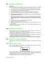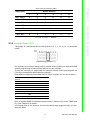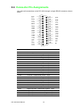
1
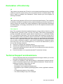
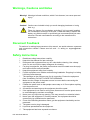
User Manual PCL-833 3-axis Quadrature Encoder & Counter Card Copyright The documentation and the software included with this product are copyrighted 2007 by Advantech Co., Ltd. All rights are reserved. Advantech Co., Ltd. reserves the right to make improvements in the products described in this manual at any time without notice. No part of this manual may be reproduced, copied, translated or transmitted in any form or by any means without the prior written permission of Advantech Co., Ltd. Information provided in this manual is intended to be accurate and reliable. However, Advantech Co., Ltd. assumes no responsibility for its use, nor for any infringements of the rights of third parties, which may result from its use. Acknowledgements Intel and Pentium are trademarks of Intel Corporation. Microsoft Windows and MS-DOS are registered trademarks of Microsoft Corp. All other product names or trademarks are properties of their respective owners. Product Warranty (2 years) Advantech warrants to you, the original purchaser, that each of its products will be free from defects in materials and workmanship for two years from the date of purchase. This warranty does not apply to any products which have been repaired or altered by persons other than repair personnel authorized by Advantech, or which have been subject to misuse, abuse, accident or improper installation. Advantech assumes no liability under the terms of this warranty as a consequence of such events. Because of Advantech’s high quality-control standards and rigorous testing, most of our customers never need to use our repair service. If an Advantech product is defective, it will be repaired or replaced at no charge during the warranty period. For outof-warranty repairs, you will be billed according to the cost of replacement materials, service time and freight. Please consult your dealer for more details. If you think you have a defective product, follow these steps: 1. Collect all the information about the problem encountered. (For example, CPU speed, Advantech products used, other hardware and software used, etc.) Note anything abnormal and list any onscreen messages you get when the problem occurs. 2. Call your dealer and describe the problem. Please have your manual, product, and any helpful information readily available. 3. If your product is diagnosed as defective, obtain an RMA (return merchandize authorization) number from your dealer. This allows us to process your return more quickly. 4. Carefully pack the defective product, a fully-completed Repair and Replacement Order Card and a photocopy proof of purchase date (such as your sales receipt) in a shippable container. A product returned without proof of the purchase date is not eligible for warranty service. 5. Write the RMA number visibly on the outside of the package and ship it prepaid to your dealer. Edition 2 Printed in Taiwan PCL-833 User Manual February 2008 ii Declaration of Conformity CE This product has passed the CE test for environmental specifications when shielded cables are used for external wiring. We recommend the use of shielded cables. This kind of cable is available from Advantech. Please contact your local supplier for ordering information. CE This product has passed the CE test for environmental specifications. Test conditions for passing included the equipment being operated within an industrial enclosure. In order to protect the product from being damaged by ESD (Electrostatic Discharge) and EMI leakage, we strongly recommend the use of CE-compliant industrial enclosure products. FCC Class B Note: This equipment has been tested and found to comply with the limits for a Class B digital device, pursuant to part 15 of the FCC Rules. These limits are designed to provide reasonable protection against harmful interference in a residential installation. This equipment generates, uses and can radiate radio frequency energy and, if not installed and used in accordance with the instructions, may cause harmful interference to radio communications. However, there is no guarantee that interference will not occur in a particular installation. If this equipment does cause harmful interference to radio or television reception, which can be determined by turning the equipment off and on, the user is encouraged to try to correct the interference by one or more of the following measures: Reorient or relocate the receiving antenna. Increase the separation between the equipment and receiver. Connect the equipment into an outlet on a circuit different from that to which the receiver is connected. Consult the dealer or an experienced radio/TV technician for help. Technical Support and Assistance 1. 2. Visit the Advantech web site at www.advantech.com/support where you can find the latest information about the product. Contact your distributor, sales representative, or Advantech's customer service center for technical support if you need additional assistance. Please have the following information ready before you call: – Product name and serial number – Description of your peripheral attachments – Description of your software (operating system, version, application software, etc.) – A complete description of the problem – The exact wording of any error messages iii PCL-833 User Manual Warnings, Cautions and Notes Warning! Warnings indicate conditions, which if not observed, can cause personal injury! Caution! Cautions are included to help you avoid damaging hardware or losing data. e.g. There is a danger of a new battery exploding if it is incorrectly installed. Do not attempt to recharge, force open, or heat the battery. Replace the battery only with the same or equivalent type recommended by the manufacturer. Discard used batteries according to the manufacturer's instructions. Document Feedback To assist us in making improvements to this manual, we would welcome comments and constructive criticism. Please send all such - in writing to: [email protected] Safety Instructions 1. 2. 3. 4. 5. 6. 7. 8. 9. 10. 11. 12. 13. 14. 15. 16. 17. Read these safety instructions carefully. Keep this User Manual for later reference. Disconnect this equipment from any AC outlet before cleaning. Use a damp cloth. Do not use liquid or spray detergents for cleaning. For plug-in equipment, the power outlet socket must be located near the equipment and must be easily accessible. Keep this equipment away from humidity. Put this equipment on a reliable surface during installation. Dropping it or letting it fall may cause damage. The openings on the enclosure are for air convection. Protect the equipment from overheating. DO NOT COVER THE OPENINGS. Make sure the voltage of the power source is correct before connecting the equipment to the power outlet. Position the power cord so that people cannot step on it. Do not place anything over the power cord. All cautions and warnings on the equipment should be noted. If the equipment is not used for a long time, disconnect it from the power source to avoid damage by transient overvoltage. Never pour any liquid into an opening. This may cause fire or electrical shock. Never open the equipment. For safety reasons, the equipment should be opened only by qualified service personnel. If one of the following situations arises, get the equipment checked by service personnel: The power cord or plug is damaged. Liquid has penetrated into the equipment. The equipment has been exposed to moisture. PCL-833 User Manual iv 18. The equipment does not work well, or you cannot get it to work according to the user's manual. 19. The equipment has been dropped and damaged. 20. The equipment has obvious signs of breakage. 21. DO NOT LEAVE THIS EQUIPMENT IN AN ENVIRONMENT WHERE THE STORAGE TEMPERATURE MAY GO BELOW -20° C (-4° F) OR ABOVE 60° C (140° F). THIS COULD DAMAGE THE EQUIPMENT. THE EQUIPMENT SHOULD BE IN A CONTROLLED ENVIRONMENT. 22. CAUTION: DANGER OF EXPLOSION IF BATTERY IS INCORRECTLY REPLACED. REPLACE ONLY WITH THE SAME OR EQUIVALENT TYPE RECOMMENDED BY THE MANUFACTURER, DISCARD USED BATTERIES ACCORDING TO THE MANUFACTURER'S INSTRUCTIONS. 23. The sound pressure level at the operator's position according to IEC 704-1:1982 is no more than 70 dB (A). Safety Precaution - Static Electricity DISCLAIMER: This set of instructions is given according to IEC 704-1. Advantech disclaims all responsibility for the accuracy of any statements contained herein.Safety Precaution - Static Electricity Follow these simple precautions to protect yourself from harm and the products from damage. To avoid electrical shock, always disconnect the power from your PC chassis before you work on it. Don't touch any components on the CPU card or other cards while the PC is on. Disconnect power before making any configuration changes. The sudden rush of power as you connect a jumper or install a card may damage sensitive electronic components. v PCL-833 User Manual PCL-833 User Manual vi Contents Chapter Chapter 1 Overview...............................................1 1.1 1.2 1.3 1.4 1.5 Introduction ............................................................................................... 2 Features .................................................................................................... 2 Specifications ............................................................................................ 3 1.3.1 Encoder input................................................................................ 3 1.3.2 Digital input ................................................................................... 3 1.3.3 Programmable interrupt controller ................................................ 3 1.3.4 General ......................................................................................... 3 Block Diagram........................................................................................... 4 Initial Inspection ........................................................................................ 5 2 Installation & Jumpers ........................7 2.1 2.2 2.3 Hardware installation................................................................................. 8 Software Installation.................................................................................. 8 Switch & Jumper Settings ......................................................................... 8 2.3.1 Base I/O Address (SW1)............................................................... 8 2.3.2 Interrupt level (JP1)....................................................................... 9 Connector Pin Assignments.................................................................... 10 2.4.1 Connector Wiring ........................................................................ 11 2.4 Chapter 3 Advanced Modes ...............................13 3.1 Quadrature Encoder Introduction............................................................ 14 3.1.1 Single-ended vs. differential input............................................... 14 Counter Modes........................................................................................ 15 Digital Noise Filter ................................................................................... 16 Latch Mode ............................................................................................. 16 Counter Reset Values ............................................................................. 17 3.5.1 Reset after latch.......................................................................... 17 Cascade Mode ........................................................................................ 17 Timer Functions ...................................................................................... 18 Interrupt Functions .................................................................................. 18 3.2 3.3 3.4 3.5 3.6 3.7 3.8 vii PCL-833 User Manual PCL-833 User Manual viii Chapter 1 Overview Introduction Features Specifications Block Diagram 1 1.1 Introduction The PCL-833 is a 3-axis quadrature encoder and counter add-on card for the KM PC/ AT and compatibles (ISA bus). This card lets your PC perform position monitoring for motion control systems. It provides three 24-bit up/down counters as quadrature encoders and a 16-MHz oscillator time base with wide-range multiplier. An on-board interrupt controller handles nine different interrupt sources. Encoder interface Each input includes a decoding circuit for incremental quadrature encoding. Inputs accept either single-ended or differential signals. Quadrature input works with or without an index, allowing linear or rotary encoder feedback. Counters The PCL-833 has three independent 24-bit counters. The maximum quadrature input rate is 1.0 MHz, while the maximum input rate in counter mode is 2.4 MHz. You can individually configure each counter for quadrature decoding, pulse/direction counting or up/down counting. Digital input and interrupts The PCL-833 provides five digital input channels. The channels accept digital input as an index input for a rotary encoder or as a home sensor input for a linear encoder. The card can generate an interrupt to the system based on a signal from its digital inputs, overflow/underflow of its counters or on a programmed time interval. It can repeatedly generate interrupts at anytime interval you specify, 0.I mini sec to 255 sec. These interrupts let you precisely monitor the speed of a control system. 1.2 Features Three 24-bit up/down counters (cascade for up to 48 bits) 1.0 MHz max quadrature input rate 2.4 MHz max. input pulse rate Single ended or differential inputs Pulse/direction and up/down counter XI, X2, X4 counts for each encoder cycle Optically isolated up to 2500 V' 4-stage digital filter with selectable sampling rate 16-MHz oscillator time base with wide-range multiplier. Onboard interrupt controller with nine different interrupt sources Digital input with interrupt for each axis Programmable time interval interrupt Half-size AT-bus card PCL-833 User Manual 2 1.3.1 Encoder input No. of Axes: Three independent axes Max. quadrature input freq.: 1.0MHz Max. input pulse freq.:2.4MHz Counts per encoder cycle: 1,2 or 4 (s/w selectable) Encoder type: Single-ended or differential Counter size: 24 bits, easily daisy-chain for up to 48 bits Counter modes: Quadrature, up/down, count/direction (s/w selectable) Digital filter: 4 stage Sample clock freq.: 8,4, or 2MHz (s/w selectable) Input isolation: 2,500VRMS using optical isolators 1.3.2 Digital input No. of channels: five differential, with interrupt. Input isolation: 2,500VRMS using optical isolators 1.3.3 Programmable interrupt controller 10-Hz, 1-KHz, or 10-KHz time base (s/w selectable) with a programmable multiplier from 1 to 255 1.3.4 General Connector: DB-25 Board dimensions: 185 * 100mm 3 PCL-833 User Manual Overview Chapter 1 1.3 Specifications 1.4 Block Diagram PCL-833 User Manual 4 After receiving your PCL-833 package, please inspect its contents first. The package should contain the following items: PCL-833 encoder card Companion CD-ROM (DLL driver included) Startup user Manual Chapter 1 The PCL-833 card harbors certain electronic components vulnerable to electrostatic discharge (ESD). ESD could easily damage the integrated circuits and certain components if preventive measures are not carefully paid attention to. Before removing the module from the antistatic plastic bag, you should take following precautions to ward off possible ESD damage: Touch the metal part of your computer chassis with your hand to discharge static electricity accumulated on your body. One can also use a grounding strap. Make contact between the antistatic bag and ground before opening. Overview 1.5 Initial Inspection After taking out the module, you should first: Inspect the module for any possible signs of external damage (loose or damaged components, etc.). If the module is visibly damaged, please notify our service department or our local sales representative immediately. Avoid using a damaged module with your system. Avoid physical contact with materials that could hold static electricity such as plastic, vinyl and Styrofoam. 5 PCL-833 User Manual PCL-833 User Manual 6 Chapter 2 2 Installation & Jumpers Hardware Installation Software Installation Switch & Jumper Settings Connector Pin Assignments 2.1 Hardware installation Warning! Disconnect power from PC when you install or remove the PCL-833 or its cable 1. Turn off the computer and all peripheral devices (such as printers and monitors). 2. Disconnect the power cord and any other cables from the back of the computer. Turn the chassis so the back of the unit faces you. 3. Remove the chassis cover (see your computer users guide if necessary). 4. Locate the expansion slots at the rear of the unit and choose an unused slot. 5. Remove the screw that secures the expansion slot cover to the chassis. Save the screw to secure the PCL-833. 6. Carefully grasp the upper edge of the PCL-833 card. Align the hole in the retaining bracket with the hole on top of the expansion slot, and align the gold striped edge connector with the expansion slot socket. Press the board firmly into the socket. 7. Replace the screw in the expansion slot retaining bracket 8. Attach necessary accessories to the card 9. Replace the chassis cover. Connect the cables you removed in step2. Turn on the computer. Hardware installation is now complete. You can now install the software driver as described in the next section. 2.2 Software Installation We recommend you install the software driver before installing the PCL-833 card, since this will guarantee a smooth installation process. The DLL driver Setup program for the PCL-833 module is included on the companion CD-ROM that is shipped with your module package. For further information on driver-related issues, an online version of the Device Drivers Manual is available by accessing the following path: Start\Programs\Advantech Automation \Device Manager\Device Driver Manual 2.3 Switch & Jumper Settings DIP switch SW1 sets the card's I/O address and jumper JPI sets the card's interrupt level. 2.3.1 Base I/O Address (SW1) The PCL-833 requires 16 consecutive I/O addresses. DIP switch SW1 (shown below) sets the base I/O address. Choose a base address that is not in use by any other I/O device. A conflict with another device may cause one or both devices to fail. The factory address setting (hex 200) is usually free as it is reserved for PC prototype boards. Jumper settings for various base addresses appear below: PCL-833 User Manual 8 Range (hex) Switch Position 2 3 4 5 6 200 - 20F(*) X O O O O O 210 - 21F X O O O O X 220 - 22F X O O O X O 230 - 23F X O O O X X 240 - 24F X O O X O O … … … … … … … 3F0 - 3FF X X X X X X X = Off, O = On, * = Default 2.3.2 Interrupt level (JP1) The jumper JP1 selects the card's interrupt level (2, 4, 5, 7, 10, 11, 12, 15) as shown below: Card interrupt (default = 7) Do not select a level that is being used by another device unless you have performed special programming to share several devices on one interrupt. To use the interrupt you must install an interrupt service routine and program the PCL-833's on-board the 8259 interrupt controller. Nine different conditions can enable the PCL-833's interrupt, but only one at a time. Interrupt Source Condition 0 CH1 overflow 1 CH2 overflow 2 CH3 overflow 3 CH1 ZIN 4 CH2 ZIN 5 CH3 ZIN 6 DI0 7 Shared by TIMER and DI1 Bit 3 of register BASE+9 switches interrupt source 7 between the card's TIMER and Dl1. See Chapter 3 for details. You should treat all the interrupt sources as positive-edge triggered when you program the 8259. 9 PCL-833 User Manual Installation & Jumpers 1 Chapter 2 Table: Card I/O Address (SW1) 2.4 Connector Pin Assignments You make all connections to the PCL-833 through a single DB-25 connector, shown below: Pin Function EGND External ground CH1A- Channel 1 A differential negative - input CH1A+ Channel 1 A differential positive - input CH1B- Channel 1 B differential negative - input CH1B+ Channel 1 B differential positive - input CH1Z- Channel 1 Z differential negative - input CH1Z+ Channel 1 Z differential positive - input CH2A- Channel 2 A differential negative - input CH2A+ Channel 2 A differential positive - input CH2B- Channel 2 B differential negative - input CH2B+ Channel 2 B differential positive - input CH2Z- Channel 2 Z differential negative - input CH2Z+ Channel 2 Z differential positive - input CH3A- Channel 3 A differential negative - input CH3A+ Channel 3 A differential positive - input CH3B- Channel 3 B differential negative - input CH3B+ Channel 3 B differential positive - input CH3Z- Channel 3 Z differential negative - input CH3Z+ Channel 3 Z differential positive - input CDI0- Digital input NO. 0 differential negative - input CDI0+ Digital input NO. 0 differential positive - input CDI1- Digital input NO. 1 differential negative - input CDI1+ Digital input NO. 1 differential positive - input PCL-833 User Manual 10 Differential/single-ended input With differential inputs connect the negative wire to the negative pin and the positive wire to the positive pin. For example, with channel 3A connect the negative input wire to CH3A- and the positive wire to CH3A+. With single-ended inputs connect the input to the positive pin and leave the negative pin open. 11 PCL-833 User Manual Installation & Jumpers AB phase encoder In 2-pulse input mode A inputs (CHIA, CH2A, etc.) count up while their corresponding B inputs (CHIB, CH2B) count down. In I-pulse input mode A inputs (CHIA, etc.) count up or down and B inputs (CHIB, etc.) determine the direction to count. A logical high (1) on the B channel indicates that the pulse on the A channel is an up count, and a logical low (0) indicates that the pulse is a down count Chapter 2 2.4.1 Connector Wiring PCL-833 User Manual 12 Chapter 3 3 Advanced Modes Quadrature Encoder Introduction Counter Modes Digital Noise Filter Latch Mode Counter Reset Values Cascade Mode Timer Functions Interupt Functions 3.1 Quadrature Encoder Introduction In typical closed-loop control systems, also know as servo systems, the encoder interface senses motor position and sends a position signal to the controller. The diagram below shows a typical servo system. The encoder generates pulses which indicate the shaft position. The encoder output includes two signals, commonly called channel A and channel B, which generate N pulses per revolution. The two signals are shifted by a quarter of a cycle, as shown below. The shift between the two signals enables the controller to determine the direction of rotation, depending on whether channel A leads channel B or vice versa. (encoder. tif) 3.1.1 Single-ended vs. differential input Most encoders produce square wave signals with TTL levels. Industrial systems often use encoders with differential signals, i. e. channel A and B and their complements. Differential signals can reduce sensitivity to noise and allow longer transmission distances. Encoders may also produce a third signal once per revolution known as the index or marker. The encoder interface can use the index signal to reset the counter, allowing you to monitor the position within the current revolution. PCL-833 User Manual 14 The following table shows the maximum input rate for each input mode and system clock rate. Values are given for each system clock frequency. Mode 2MHz 300KHz 600KHz 600KHz Counter modes are as follows Quadrature input counter mode Quadrature input consists of two square wave inputs (A and B) which are 90-drgess out of phase. The PCL-833 counts the square wave transitions and determines the direction by comparing whether channel A is leading channel B or vice versa. There are three different counting methods in quadrature input mode. X1 The counter will increment (or decrement) the counter whenever a rising edge occurs on input channel A. X2 The counter will increment (or decrement) whenever a rising or falling edge occurs on input channel A. X4 The counter will increment (or decrement) whenever a rising or falling edge occurs on input channel A or B. 2-pulse mode In 2-pulse mode the PCL-833 uses two input pulses as counting sources: one for clockwise (CW) and one for counter clockwise(CCW) counting. The counter will decrement whenever a rising edge occurs on channel A. It will increment whenever a rising edge occurs on channel B. Pulse/direction mode In pulse/direction mode the PCL-833 uses one input line (A) for pulse input and one line (B) for direction. If channel B is high (1), the counter will decrement whenever a rising edge occurs on channel A. If channel B is low (0), the counter will increment whenever a rising edge occurs on channel A. Disabled mode PCL-833 will not accept input, but you can still access all its registers You select the mode by programming the card's registers: BASE+O for CHI, BASE+I for CH2 and BASE+2 for CH3. 15 PCL-833 User Manual Advanced Modes Quadrature X1, X2, X4 2-pulse Pulse/direction Maximum input rate 8MHz 4MHz 1MHz 600KHz 2.4MHz 1.2MHz 2.4MHz 1.2MHz Chapter 3 3.2 Counter Modes 3.3 Digital Noise Filter Noise immunity is the most important requirement for reliable encoder interface operation. The PCL-833 conditions the input signals with a four stage digital filter. This filter reduces glitches (digital noise) or spikes by sampling the input at 2, 4 or 8 MHz. The filter output waveforms change only when an input has the same value for three consecutive sampling edges. The filter thus rejects noise or pulses shorter than two sampling clock periods. You can optimize noise immunity by selecting the lowest sampling frequency that compatible with the highest input rate you expect. The PCL-833 accepts up to I MHz quadrature freq. at 8 MHz filter sampling speed. At 2 MHz sampling speed it can still accept up to 300KHz quadrature input freq. A 3600 rpm motor with 2000 ppr encoder will have a max. quadrature freq. of 3600 x 200 0 / 60 = 120 KHz. In the above example the 2MHz sampling clock will have the best noise immunity and will meet the required input freq. The following table shows the maximum noise pulse width that the filter will reject for each system clock frequency: Clock freq. Maximum width 8MHz 375nsec 4MHz 750nsec 2MHz 1.5msec 3.4 Latch Mode When you read a counter, you are actually reading a value latched into a buffer. The PCL-833 provides five different latching modes, only one of which is active at any given time. Make sure that you know which latching mode is current whenever you read the counter. Otherwise, you may read an old value or one that was latched at a different time than you expect. You select the latching mode for each channel individually. That is, you might select S/W latching on channel I and DIO latching for channels 2 and 3. Bits 0-2 of register BASE+3 control CHI, BASE+4control CH2 and BASE+5 control CH3. The PCL-833's latching modes are as follows S/W latch Whenever you read a channel's data registers, the counter values will be latched in buffer. The S/W latch will only take effect when you read the high byte of the counter (C23-C16). Reading middle byte or low byte of a counter won't latch the counter values to the buffer. You should therefore read the high byte first, then the other two bytes of the counter. Index latch A rising edge on the channel's index input line will latch the channel's counter value. PCL-833 User Manual 16 Dl1 latch A rising edge on the Dl1 line will latch the counter value for the channel. Timer latch The card latches the counter value on a rising edge of pulses from the card's onboard timer. Bit 3 (RF) of registers BASE+O, I and 2 control the initial (reset) value of for each counter. You can select either 000000 or 800000(hex). When the counter is reset, it will take this value. When RF = 0, the counter will reset to 000000h When RF = 1, the counter will reset to 800000h 3.5.1 Reset after latch Bit 3 (LC) of registers BASE+3, 4 and 5 determine whether the corresponding counter will reset to its initial value (see preceding section) when it is latched. lf LC = I, the counter will reset to its initial value when it is latched lf LC = 0, the counter will stay the same (keep its previous value)when it is latched. 3.6 Cascade Mode 24 bits is enough for most counter applications. If you need to store larger values, you can cascade the output of one counter into the input of a second, giving 48 bits of storage. When the first counter over-flows, the card increments the second counter. The PCL-833 lets you cascade channel I into channel 2 to form a single 48-bit counter. (Channel 3 will not cascade.) The mode settings of channel I control this 48-bit counter, except that the setting of channel 2 controls the initial (reset) value. You set up the 48-bit counter as follows 1. Set bits CAS1 and CAS0 of write register BASE+8 to 0lh 2. Set CH2 to cascade mode. (Set Bits 0-2 of register BASE+1 to "111". 3. Set the initial (reset) value in CH2 4. Set remaining modes in CH1 To read the total value, you must read both counters. Channel 1 holds the high 24bits and channel 2 the low 24-bits. 17 PCL-833 User Manual Advanced Modes 3.5 Counter Reset Values Chapter 3 DI0 latch A rising edge on the board's DIO line will latch the counter value for the channel. 3.7 Timer Functions The PCL-833's on-board timer lets you monitor counter readings with extreme accuracy. The programmable timer generates pulses at regular intervals. The card can latch the readings in its counters and generate an interrupt to the PC. You can set timer cycle periods from 1msec. to 255 seconds. The cycle time is the product of the timer base period and a multiplier. Timer base periods are 1,10,100 or 1000 msec. The multiplier ranges from 1 to 255. The divider can range from 1 to 255. For example, to set a timer period of 20 msec, you would set the timer base to1 msec and the multiplier to 20. That is: Time period = Base period * multiplier 20msec = 1msed * 20 Set the timer period by programming registers BASE+9 and BASE+10. You can use the timer to latch the counter values and/or to generate an interrupt to the PC. To use the timer latching set registers BASE+3, 4and 5. To generate an interrupt with the timer set bit 3 of BASE+9 and program the card's 8259A interrupt controller. See the following sections for more information. 3.8 Interrupt Functions The PCL-833 can generate an interrupt to the PC for any of the following conditions: 1. Counter I overflow 2. Counter 2 overflow 3. Counter 3 overflow 4. Counter I index in 5. Counter 2 index in 6. Counter 3 index in 7. DI0 input 8. Dl1 input 9. Timer pulse The card's 8259A interrupt controller chip combines these interrupts into a single PC interrupt, set by jumper JPI. Since the 8259A only has eight input channels, the Dl1 and timer interrupts share a single interrupt line. Bit 3 of write register BASE+9 selects Dl1 or timer. Note that you can use only one of the card's interrupt sources at a given time, unless you specially program your interrupt service routine to handle multiple interrupt sources. You enable the PCL-833 interrupt functions by programming the card's 8259 chip, accessed through the registers at BASE+12 and BASE+13. You will need to set the chip's interrupt mask register to exclude all but one of the interrupt lines. Program the 8259 in 8086/8088 mode, single mode, edge-triggered mode. In 8086/ 8088 mode two INTA signals are needed. The PCL-833 generates the first INTA automatically. Your program generates the second INTA by reading BASE+15. This read returns the interrupt vector number which caused the request. The hold time must be at least 1 micro sec after a low-to-high transition of the interrupt source to ensure that the interrupt occurs. PCL-833 User Manual 18 Chapter 3 Advanced Modes PCL-833 User Manual 19 www.advantech.com Please verify specifications before quoting. This guide is intended for reference purposes only. All product specifications are subject to change without notice. No part of this publication may be reproduced in any form or by any means, electronic, photocopying, recording or otherwise, without prior written permission of the publisher. All brand and product names are trademarks or registered trademarks of their respective companies. © Advantech Co., Ltd. 2007