1
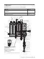
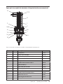
Water Sampling Station PM04
Measurement of free chlorine or chlorine dioxide
EN
02
Operation &
Maintenance Instructions
Read these operation and maintenance instructions
before start up!
To be held for future reference.
Contents
1. General and Safety Instructions........................................................................... 4
1.1 General........................................................................................................... 4
1.2 Warning symbols used in this Operation & Maintenance Manual......................... 4
1.3 Qualification and training of personnel.............................................................. 4
1.4 Important safety instructions............................................................................ 4
1.5 Hazards due to non-compliance with safety instructions.................................... 5
1.6 Safe operation................................................................................................. 5
1.7 Safety instructions for the owner/operator......................................................... 5
1.8 Safety instructions for inspection-, maintenance-, and installation work.............. 5
1.9 Unauthorized modifications and production of spare parts.................................. 6
1.10 General notes of instruction!.......................................................................... 6
1.11 Scope of delivery........................................................................................... 6
1.12 Disposal........................................................................................................ 6
2. Assembly............................................................................................................... 7
2.1 General........................................................................................................... 7
2.2. Measurement of free chlorine and/or chlorine dioxide..................................... 10
2.3. Measuring the “pH-value”, “redox-potentials” and “temperature” . .................. 10
4. Installation.......................................................................................................... 12
4.1 Hydraulic connection..................................................................................... 12
4.2 Electric connection........................................................................................ 14
5. Setting-up........................................................................................................... 15
5.1 Installation of the sensors.............................................................................. 15
5.2 Adjusting the test water quantity..................................................................... 15
5.3 Calibrating the measurement amplifier............................................................ 15
6. Operating............................................................................................................. 17
7. Turning the unit off............................................................................................. 17
8. Maintenance....................................................................................................... 18
9. Technical Data.................................................................................................... 19
10. Installation example......................................................................................... 20
| Operating manual PM04 | Contents
11. Order documents.............................................................................................. 21
11.1. Pre-assembled instrument panel................................................................. 21
11.2. Accessories and spare parts........................................................................ 21
12. Fault analysis.................................................................................................... 22
13. Spare parts........................................................................................................ 23
15. Declaration of harmlessness............................................................................ 29
16. Revision............................................................................................................. 30
17. Warranty............................................................................................................ 31
Contents | Operating manual PM04 | 1. General and Safety Instructions
1.1 General
This Operation & Maintenance Manual contains basic information to be noted during installation, operation and maintenance. It is therefore essential that the contractor read the
manual before installing and commissioning the pump/system as well as by the relevant
operating personnel/owner of the pump/system. It must remain accessible at the dosing
pump/system for reference at all times.
In addition to the general safety instructions under this main heading of Safety, the special
safety precautions outlined another section must also be observed.
1.2 Warning symbols used in this Operation & Maintenance Manual
This Operation & Maintenance Manual contains vital information, which may endanger
people, the environment and the dosing pump/system if disregarded. These statements
are identified by the following symbols:
DANGER! Refers to an imminent danger. Non-compliance can lead to death or serious
injury.
WARNING! Refers to a potentially hazardous situation. Non-compliance can lead to death
or serious injury.
CAUTION! Refers to a potentially hazardous situation. Non-compliance can lead to minor
injury or property damage.
NOTICE! or INFORMATION! Appear in conjunction with safety instructions, which may
endanger the pump/system and its operation if disregarded.
IMPORTANT! Draws attention to supplementary information to make the work easier and
ensure trouble free operation.
1.3 Qualification and training of personnel
The personnel employed for installation, operation, inspection and maintenance work
must be qualified to do so. The areas of responsibility, competence and supervision of the
personnel must be precisely defined by the owner. Personnel who do not have the required
knowledge must be duly rained and instructed. If necessary, this training can also be
provided by the manufacturer/supplier on behalf of the dosing pump’s owner. In addition,
the owner of the system must ensure that the relevant personnel are fully familiar with and
have understood the contents of this Operation & Maintenance Manual.
1.4 Important safety instructions
When installing and using this electrical equipment, basic safety precautions should
always be followed, including the following:
1.) Read and follow all instructions!
2.) WARNING! To reduce risk of injury, do not permit children to use this product
unless they are closely supervised at all times.
WARNING!
| Operating manual PM04 | General and Safety Instructions
3.) WARNING! Risk of electric shock. Connect only to a grounding type receptacle
protected by a ground-fault circuit-interrupter (GFCI). Contact a qualified electrician if you cannot verify that the receptacle is protected by a GFCI.
4.) Do not bury the cord. Locate the cord to minimize abuse from lawn mowers, hedge
trimmers, and other equipment.
WARNING!
5.) WARNING! To reduce the risk of electric shock, replace damaged cord immediately.
6.) WARNING! To reduce the risk of electric shock, do not use an extension cord
to connect the unit to the electricity supply; provide a properly located outlet.
WARNING!
7.) Save these instructions!
1.5 Hazards due to non-compliance with safety instructions
Failure to comply with safety instructions may endanger not only people, but also the environment and the dosing pump/system. Non-compliance with the safety instructions can
lead to the loss of all entitlement to damages. The following hazard in particular may arise:
- Danger to people due to electrical, mechanical and chemical effects. - Failure of system
functions. - Danger to the environment due to leakage of hazardous substances. 1.6 Safe operation
The safety instructions in this Operation & Maintenance Manual must be observed.
The owner is responsible for ensuring the compliance with local safety regulations.
1.7 Safety instructions for the owner/operator
Leakages (e.g. due to ruptures in the lining) of hazardous substances (e.g. toxic or
abrasive) must be discharged in such a way as to exclude all danger to people and the
environment. Statutory regulations must be observed.
Danger due to electric current must be excluded (for further details, refer to the German
VDE standards as well as local regulations or chapter 1.4).
1.8 Safety instructions for inspection-, maintenance-, and installation work
The owner must ensure that all inspection, maintenance and installation work is undertaken by authorized and duly qualified personnel who have also studied this Operation &
Maintenance Manual.
The dosing pump must always come to a complete stop before starting any work on the
pump. The procedure specified in this Operation & Maintenance Manual for shutting down
the Dosing/pump/system must be observed without fail.
Dosing pumps or systems in contact with potentially harmful media must be decontaminated. All safety mechanisms and guards must be refitted and reactivated as the work is
completed.
General and Safety Instructions | Operating manual PM04 | WARNING!
1.9 Unauthorized modifications and production of spare parts
The device may only be modified or converted in consultation with the manufacturer.
Genuine spare parts and accessories authorized by the manufacturer ensure greater
safety. The use of other parts can void the liability for the subsequent consequences.
1.10 General notes of instruction!
Measuring cables must not be laid parallel or close to power supply or high-voltage current
lines. Interferences would mutilate the measurement. At close distances, power supply and
measuring lines may only cross at a 90° angle.
The admissible length of the measuring cables must be adhered to with regard to the sensor used. It is of decisive importance whether high-impedance (e.g. pH value) or low-impedance (e.g. free chlorine sensor) measurements are carried out. In the case high-impedance measurements, make sure that the (plug) connections are clean and dry (plug) and
the lines do not become brittle due to sharp buckling. The screened cables normally used
for such measuring lines must be handled according to the prescribed quality. Screening
may only be connected to ground at one end of the cable (preferably at the controller).
Interface lines must be twisted and screened (see recommended cables).
IMPORTANT!
IMPORTANT!
If possible, a continuous cable from sensor to measuring input should be used.
An extension of the cable by plugs or terminal socket increases the risk of disturbances due to contamination, humidity or excessive transition resistances.
1.11 Scope of delivery
IMPORTANT!
Please unpack the product and ordered accessories with great care in order not
to miss any small parts. Immediately compare the scope of delivery with the
delivery note. The cause of any discrepancies must be determined.
IMPORTANT!
1.12 Disposal
Should the device need to be permanently taken out of operation, please bear in mind that
it contains electrolytic capacitors and must therefore be disposed of accordingly.
| Operating manual PM04 | General and Safety Instructions
2. Assembly
2.1 General
For hygiene reasons the drinking water or other water with which people come in
direct contact has to be treated frequently with agents that kill off any micro organisms
contained therein. Chlorine or chlorine compounds are mainly used for this purpose as
“disinfectants”. A high level of safety is an absolute necessity for the user in this sensitive
area, therefore one uses devices that fully automatically monitor, regulate and record the
concentration of disinfectant.
To measure the amount of free chlorine or chlorine dioxide, ampere-metric sensors are
fitted in the PM04 instrument panel (3 electrode systems for a potentiostatic operating
mode). Depending on the level of the assembly further water parameters can be measured, such as pH-value, redox-potentials and the temperature.
An electronic controller, e.g. the TOPAX model, which shows and evaluates the sensor
values, can be fitted directly onto the instrument panel.
This provides a compact measuring and regulating unit to control the actuating elements
like the regulating valve or dosing pump.
IMPORTANT!
The “test water channel “ is of crucial importance for perfect “measuring results”.
Therefore, before installing, carefully read through the information in particular regarding
hydraulic installation.
Assembly | Operating manual PM04 | IMPORTANT!
30
Controler optional
670
730
O,9
30
20
280
320
Fig. 2.1: Dimensional drawing of the PM04
| Operating manual PM04 | Assembly
20
Depending on the design, the sensors are fitted in a transparent “multi-functional control
block”. In detail, it concerns the following functions:
11
10
7
4
8
3
12
2
13
1
9
6
5
14
Fig. 2.2: View of the multi-functional control block
Key:
① measuring water inflow
② filter
③ needle valve DN 2,5
④ central drainage pipe of the overflow piping
⑤ pivoting drainage pipe for manual water testing
⑥ excess chlorine measurement cell
⑦ reference electrode for excess chlorine measurement cell
⑧ floating elements with bar magnet
⑨ dry reed contact
⑩ potentials-adjustment pin
⑪ receptacle holes for the pH- and REDOX-single-rod measuring cell
⑫ receptacle holes for the temperature gauge Pt100
⑬ water drainage from the measurement cell with PVC-pipe
⑭ collection hopper
Assembly | Operating manual PM04 | 2.2. Measurement of free chlorine and/or chlorine dioxide
The measuring of excess chlorine works in accordance with the ampere-metric measurement principle with free measuring electrodes, i.e. the measuring electrode is in direct
contact with the test water.
Ampere-metric sensors can be divided by the following criteria:
• 2-electrodes system
• 3- electrodes system with potentiostatic connection
A potentiostatic measuring cell is fitted on the PM 04 instrument panel to measure the
concentration of disinfectant. It contains a “gold electrode” as a measuring electrode, a
(high-grade steel electrode” as a backing electrode and a “glass reference electrode” (KCI).
The potentiostatic connection is integrated in the corresponding measurement amplifier.
A specific D.C. voltage is set on the measuring cell by the potentiostatic connection in the
measurement amplifier, which polarises the measurement cell. It is therefore not necessary to zero calibrate this cell.
The current only flows with the addition of free chlorine and/or chlorine dioxide. This current increases proportionally to the concentration. The content of disinfectants is verified
and the measurement amplifier is calibrated with the help of the comparative measurement as per the DPD1 method.
The excess chlorine measurement is heavily dependent on the pH-value.
Consequentially there is a need for the constant pH-value of the water to be analysed
to be at preferably pH 7.20 or lower. Otherwise the same chlorine content would give
different readings. The condition of the chlorine in the water changes depending on the
pH-value and therefore so does the measurement signal. At pH 7.00 approx. 20% of the
free chlorine is dissociated into hypochlorite (CIO-), and at 8.00 pH already about 80%. Hypochlorite (ClO-) only has a small disinfecting effect and therefore only produces a smaller
current at the measurement cell.
The chlorine dioxide measurement only depends to a lesser extent on the pHvalue.
In the potentiostatic measurement cell of the PM 04 instrument panel, rotating balls in the
water current ensure the continuous cleaning of the electrodes. After the intake phase of
a couple of hours they secure a long-term stability of the chlorine measurement. It is not
necessary to clean the measuring cells by hand at specific intervals.
2.3. Measuring the “pH-value”, “redox-potentials” and “temperature”
The receptacle holes for the pH and redox single-rod measuring cells and a Pt100
temperature sensor are located in the transparent flow-through casing. The sensors are
screwed directly onto the flow-through casing. The single-rod measuring cells can be hung
up with mounting plates on the acrylic-block during calibration.
10 | Operating manual PM04 | Assembly
3. Functions
All of the following functional units of the instrument panel are located in a transparent
multi-functional control block:
• potentiostatic chlorine measurement cells with electrode cleaning without zero point
calibration
• pH- and Redox- single-rod measuring cells (depending on the design)
• hydrostatic through flow with vapour lock- separator for an even through current for
the measurement cell
• Test water filter to protect the measurement cell from abrasive dirt
• Fine tuned valve to adjust the water current
• Flow through monitoring – contact “test water deficiency” for the controller
• Potentials-adjustment pin to discharge unwanted and disruptive foreign potentials.
• Sample withdrawal for manual water testing when calibrating
Functions | Operating manual PM04 | 11
4. Installation
If a measurement amplifier or controller is installed on the instrument panel, then it has to
be mounted at such a height on the wall that the operator can read off the controller and
operate the electronic automatic controller with ease. The test water must be able to drain
down freely from the panel.
Use the screws and washers provided to fix it to the wall. These are purpose made with
regard to the size and material of this application. Install the instrument panel without
mechanical tension! The nuts are to be adjusted on the threaded rods in such a way that
all four fixing points are all on one level.
4.1 Hydraulic connection
4.1.1. Water inflow
The test water travels through plastic tubes or hoses made of PVC or PE. Under no circumstances may metal tubes be used, as they can falsify the measurement through chlorine
loss through shrinkage.
The test water must be carried to the instrument panel with as little deceleration as possible, so that it is possible to control the water quality well. Brief dead times are attained
by using the shortest possible hoses and smallest possible cross sections. 50 metre long
pipes DN 6 already yield approx. 2 minutes of dead time. If the pipe’s cross section were
widened to DN 15 due to losses from friction in the pipes, then the dead time increases
to approx. 10 minutes. Therefore it is recommended for when there are great distances
between the withdrawal of the test water and the instrument panel, to build an installation
as per the following diagram (fig. conduit with water pump gauge).
The use of a measuring water pump is useful if the test water is not flowing through with
enough pressure (at least 0.2 bar at the connection with the instrument panel). Long
periods of deceleration due to the great distance between the withdrawal point and the
measuring panel, can be avoided, too, by using measuring water pumps.
The pump pushes the test water over the long distance in a ring circuit to the instrument
panel and only one component current is taken for the actual measurement. Under no circumstances may the throttle valve be closed, as otherwise very long deceleration periods
hinder the control. In addition the water in the pump is warmed up a lot and can lead to
measurement errors. It is helpful having a manometer in the circuit ring when adjusting the
throttle valve.
When withdrawing test water (see fig. 4.2.) the applicable regulations have to be observed.
When withdrawing test water from a pipe it must be done from the line’s centre as shown
in the diagram.
12 | Operating manual PM04 | Installation
z.B. 50 m DN15
DN 6
Fig. 4.1: Conduit with water pump gauge
Fig. 4.2: Water withdrawal gauge
Installation | Operating manual PM04 | 13
4.1.2. Water drainage
The drainage of water from the instrument panel is free from pressure. Two streams
of water run off the acrylic-block, one from the overflow pipe and one from the actual
measurement cell. Both of the water streams are pooled together in the collection hopper
at the bottom left hand corner of the instrument panel. The water for the manual tests
is withdrawn at the pivoting drainage pipe. The water from the hopper must be able to
drain downwards freely. The recirculation of water in a pressure system is possible with a
submerged pump in a collection tank, for instance (see installation example).
4.2 Electric connection
The local (DIN, VDE, ...) must be observed for the general electric installation. A specialist
must always carry out the electrical work.
The controller and/or measurement amplifier should be installed directly on to the instrument panel and/or for the installation of the control cabinet as near to the instrument panel
as possible. The connecting lines for the pH- and redox single-rod measuring cells, in
particular, should not be any longer than approx. 10 cm without any special precautions. If
larger distances have to be bridged, an impedance transformer then has to be put on the
electrode. Under no circumstance may the measuring cables be laid directly parallel to the
power and control lines or their pipe ducts, junctions have to be at a 90° angle. Equipotential bonding is necessary if the tension introduced causes measuring errors, especially in
the chlorine and pH measurements. The sensors are directly connected to the measurement amplifier via terminal blocks.
WARNING!
IMPORTANT!
WARNING!
Measuring cables must not be laid parallel to or in close proximity to the power lines
and/or high-voltage lines. Interfering random agents distort the measurement. Power lines
and measuring lines may only cross at close proximity at right angles. The permissible
length for the measuring line is to be considered with the given sensor in mind. It is of
crucial importance to know whether it concerns high-impedance (e.g. pH-value) or low
impedance (e.g. surplus chlorine measurement cell) measurements. For high impedance
measurements pay particular attention to ensuring that the connections and/or plug socket
are clean and dry, and that the lines are not weakened by major kinks. The shielded cables
normally used for such measuring lines have to be used in the prescribed quality.
IMPORTANT!
If possible a continuous length should be used from the sensor to the measured value
input. Extending the cable with connectors and/or connection boxes increases the risk of
disturbances through contamination, humidity or transfer resistance.
14 | Operating manual PM04 | Installation
5. Setting-up
5.1 Installation of the sensors
During the transport a plastic rod is inserted in place of the reference electrode, this stops
the glass ball from falling out of the measuring cell. The rod is removed along with the
clamping screw connection and the reference electrode is screwed in. Prior to this the Oring supplied, approx. 30 cm, is slid onto the reference electrode and serves as a centring
device.
WARNING!
When installing the reference electrode the test water may not flow, so that the glass ball
is not flushed out of the chlorine measurement cell.
The pH and chlorine single-rod measuring cells are fitted from above in the acrylic-block,
the temperature sensor if necessary, below on the side with a smaller clamping screw
connection. The cable’s connection to the pH and redox single-rod measuring cells has to
be attached with great care. Even the smallest amount of contamination or humidity leads
to false measuring results.
WARNING!
INFORMATION!
The protective caps for the glass electrodes should be removed. They are needed when
the instrument panel is shutdown to stop the electrodes getting damp.
INFORMATION!
5.2 Adjusting the test water quantity
The needle valve on the acrylic-block is set up in such a way, that some water drains off in
the overflow pipe. Fluctuations in the system’s pressure are to be expected (for example,
when the pumps are turned off overnight), so the needle valve has to be adjusted at the
lowest system pressure, so that enough flows through the measurement cell. If sufficient
test water flows, the glass balls in the chlorine measurement cell start to rotate in the
same way, the floats come up and the dry-reed contacts connect. This signals to the
electric controller that there is enough test water current and that the adjustment control
can be enabled.
5.3 Calibrating the measurement amplifier
Before the measurement amplifier is calibrated, the test water should flow for about an
hour, as the excess chlorine measurement cell needs an inflow phase before a stable
measurement value can be given out. The measurement amplifier is calibrated with the
same procedure regardless of its make.
The detailed procedure is to be taken from the user manual for the measurement amplifier
and/or controller. Before the excess chlorine measurement cell is calibrated the pH value
should be constant as varying pH values from the chemical procedures in the water create
different chlorine ions and thereby different measurements of chlorine (the chlorine measurement’s dependence on the pH-value is described in point 2.2.).
Setting-up | Operating manual PM04 | 15
WARNING!
The pH-value has a decisive influence on the chlorine measurement!
WARNING!
pH-Value
In order to calibrate the pH-measurement amplifier one requires two buffer solutions. They
should isolate the anticipated test range, (e.g. buffer solutions pH 6.8 and pH 9.28 for test
values of pH 7.2). During the calibration the pH-single-rod measuring cell can be hung up
on the mounting plates in the acrylic block.
REDOX- Potentials
Only one buffer solution is required to calibrate the REDOX- measurement amplifier. During
the calibration the REDOX-single-rod measuring cell can be hung up on the mounting
plates in the acrylic block.
WARNING!
Buffer solutions only last for a limited amount of time. Once they expire the calibration of
the sensors is unreliable.
WARNING!
Chlorine and/or chlorine dioxide measurement cells
Free chlorine and/or chlorine dioxide are measured with the same measurement cell. It is
not necessary to zero point calibrate with the potentiostatic measurement cell with 3 electrodes. This only needs to be done if either the zero point on the measurement amplifier is
moved or if the measurement amplifier implicitly requires a zero point calibration.
The “zero-status” of the measurement cell is achieved by disconnecting the cable from the
gold electrode.
After the zero-point calibration is complete the cable is connected again. If the displayed
value is set at a stable value then the slew-rate calibration can be carried out. This can
take a few minutes.
To perform the slew-rate calibration a water sample is taken from the pivot pipe on the
overflow of the measurement cell and the content of the effective chlorine and/or chlorine
dioxide ions is determined manually. For this purpose a photometer is usually used, that
works according to the DPD method.
The user manual for the photometer has to be followed to the letter and regard must be
given to cleanliness. Dirty cuvettes or fingerprints on the cuvette can cause huge errors in
the measurements.
The value determined manually is immediately set in the measurement amplifier.
WARNING!
WARNING!
For the first run the chlorine and/or chlorine dioxide measurement has to be calibrated
again after one to two days. During this time the surface of the electrodes adapts to the
chemical and mechanical operating conditions.
16 | Operating manual PM04 | Setting-up
6. Operating
When it is operating one must be careful that there is always some water flowing out of
the overflow pipe. If necessary the needle valve has to be opened a little further.
The measurement has to be checked every week unless there are local regulations stipulating shorter intervals. If need be the measurement inserts should be calibrated again.
In the same cycle a visual check should be made on the filters in the test water inflow. If
they are dirty they have to be cleaned and/or replaced, in order to avoid false measurement readings through the loss of chlorine in the filters.
7. Turning the unit off
For short interruptions to the operation, the water flow through the measurement cell
should not be stopped. An oxide coating forms on the outer surface of the electrodes, the
rotating balls remove this when the operation starts again. It is then seen as a new inflow
phase of the chlorine measurement cell. For longer shutdown periods over several days
we recommend to empty the water out of the control block and to dry out the chlorine
measurement cell. The reference electrode and the pH and REDOX- single-rod measuring
cell are to be disassembled and stored accordingly.
WARNING!
Be careful not to lose the glass balls when dismantling the electrodes
Before the pH- and REDOX- and reference electrodes are dried out they must first be
protected. To do this, the rubber protective cap and/ or storage tank supplied (depending
on the type of measurement section) are filled with KCI solution and put on the electrodes.
The electrodes are stored vertically.
Operating | Turning the unit off | Operating manual PM04 | 17
WARNING!
8. Maintenance
The annual maintenance work is limited to a visual inspection of all the components and if
necessary the cleaning of the control block with a replacement of the washers.
The service life of the single-rod measuring cell depends on the operating conditions and
the properties of the water (e.g. corrosiveness, grease, etc.). They normally last about 12
to 15 months, whereby a 50% storage time is counted on. When re-assembling the reference electrode ensure that the O-ring is mounted on the glass shaft.
The gold and high-grade steel electrodes can have a service life of several years, depending on the corrosiveness and abrasiveness of the water. They only have to be replaced
when there are strong signs of wear (e.g. very thin points on the gold wire). If there are
strong impurities on the surface of the metal, these can be carefully removed with a fine
emery cloth (e.g. grit 800).
The nozzle for the incoming flow of the potentiostatic measurement cell can be pulled out
from the side with a M5 threaded rod to clean and then be installed again.
After dismantling the complete block, the upper catch of the floating element has to be
positioned again. To check the switching function the electrical through-flow of the dry
reed contact is verified. (Floating elements above: contact closed, floating elements below:
contact opened). If the switching function does not work after the upper catch has been
adjusted, then the dry reed contact can be moved to the fine alignment in the clamping
screw connection.
INFORMATION!
Electro-chemical sensors are wear and tear parts and are not covered by the warranty
terms. .
INFORMATION!
18 | Operating manual PM04 | Maintenance
9. Technical Data
Water test panel
Mesh aperture of the filter
mm
0.5
Water requirement
l/h
approx. 45
Temperature
°C
maximum 45
Water inflow
mm
hose connection ø 6
(0.2..6 bar)
Water drain
mm
hose connection ø 10
(drain in free downward incline)
Dimensions
mm
320x680x105 (WxHxD)
Potentiostatic excess chlorine measurement cell
Test range
mg/l
0...2.00 (free chlorine)
0...1.00 (chlorine dioxide)
pH – range
pH
5.5...8.0 (only for chlorine measurement)
Electrode materials
Measuring electrode
gold
Backing electrode
high-grade steel
Reference electrode
KCl-gel filling
pH-single rod measuring cell
Test range
pH
0.00 – 14.00
mV
- 1000 – +1000
REDOX-single-rod measuring cell
Test range
Technical Data | Operating manual PM04 | 19
10. Installation example
5
7
4
6
11
10
8
2
9
1
LS
M
3
Fig. 10.1: Installation example
Key:
① Test water withdrawal
② Instrument panel PM04
③ Pump for test water recirculation
④ Dosing pump pH- adjustment
⑤ Injection point pH- adjustment
⑥ Jet pump with check valve
⑦ Drive-water pump
⑧ Chlorine gas – control valve
⑨ Chlorine gas – flow meter
⑩ Introduction of chlorine solution
⑪ Drive-water rate
20 | Operating manual PM04 | Installation example
11. Order documents
11.1. Pre-assembled instrument panel
Model
Order no..
PM 04 to measure free chlorine and/or chlorine dioxide:
potentiostatic measurement cells
with gold-, high-grade-, reference-electrodes
42200010
PM 04 to measure free chlorine and/or chlorine dioxide, pH-value
potentiostatic measurement cells
with gold-, high-grade-, reference-electrodes
pH-single-rod measuring cell
with 1.50cm measuring cable
42200011
PM 04 to measure free chlorine and/or chlorine dioxide, pH-value, temperature
potentiostatic chlorine measurement cells
with gold-, high-grade-, reference-electrodes and balls to clean the electrodes
pH-single-rod measuring cell
with 1.50cm measuring cable
temperature gauge Pt100
with 2.5m connection cable
42200012
PM 04 to measure free chlorine and/or chlorine dioxide, pH-value, REDOX
potentiostatic chlorine measurement cells
with gold-, high-grade-, reference-electrodes and balls to clean the electrodes
pH-single-rod measuring cell
with 1.50cm measuring cable
Redox-Electrode
with 1.50cm measuring cable
42200013
PM 04 to measure free chlorine and/or chlorine dioxide, pH-value, REDOX
temperature
potentiostatic chlorine measurement cells
with gold-, high-grade-, reference-electrodes and balls to clean the electrodes
pH-single-rod measuring cell
with 1.50cm measuring cable
Redox-Electrode
with 1.50cm measuring cable
temperature gauge Pt100
with 2.5m connection cable
42200014
11.2. Accessories and spare parts
Model
Order no.
Reference electrodes for the potentiostatic measuring cell
41100060
pH-single-rod measuring cell with N-cable cap screw PG 13.5
and separate connection cable
41100004
Redox- single-rod measuring cell with N-cable cap screw PG 13.5
and separate connection cable
41100011
Temperature gauge Pt 100 with fixed cable 2.5m
41100022
Special measuring cable with N-socket link for pH-value and REDOX single-rod
measuring cells; 0.60m long for instrument panel.
78103
Order documents | Operating manual PM04 | 21
12. Fault analysis
Type of fault
Possible cause
Eliminating the fault
Balls in the chlorine measurement cell rotate too slowly
and/or floating elements do
not float
Inflow water pressure too low
Install test water line with a
larger cross section. WARNING! observe delay time
Install a measuring water
pump (see 4.1 Hydraulic connection) Installation
Floating elements float up, but
the dry reed contact does not
switch to channel pass
The display of the connected
measurement amplifier varies
erratically and does not concur
with the comparative measurement
Filter in the test water line or in
the control block is dirty
Clean the filter set and/or
replace it
Blocked needle valve
Fully open the needle valve
once and install again
Inflow nozzle of the chlorine
measurement cell is very dirty
Clean the nozzle
(see 9. Maintenance)
The chlorine measurement
cell’s reference electrode is
not centred in the hole
Fit an O-Ring on the reference
electrode
(see 5.1 Installation of the
Sensors)
The adjustment between the
floating elements and the dry
reed contact is wrong
Align the upper catch for
the floating elements (see 9.
Maintenance) move poss. reed
contact in the clamping screw
connection
Dry reed contact defect
Replace the dry reed contacts
In particular during excess
chlorine measurement:
varying pH-values strongly
affects the chlorine measurement disproportionately.
(with the DPD- manual measurement even with lower pH
the active chlorine in the water
is not ascertained and so a
higher value of free chlorine is
simulated).
Stabilise the pH-value in the
water (e.g. optimise control
path, control parameters)
22 | Operating manual PM04 | Fault analysis
13. Spare parts
potentiostatic excess chlorine measuring cells (single electrodes)
Electrode
Order no.
Reference electrode with 1.5m fixed cable and O-Ring to centralise in the
acrylic-block
41100060
Gold electrode
34168
High-grade steel electrode
34146
4,5
1,2
6
7
9
10
2,11
3
8
2
12
1,2
5,13
5
25
1,2
27
20
2,14
15,16
17
18
26
5
19
24
20
Potentiostatic Measuring Cell
see draft 13.2
(Spare parts to assemble the
electrodes of the potentiostatic
measurement cell)
21
22
23
24
Fig. 13.1: Spare parts for the complete multi-control block
Spare parts | Operating manual PM04 | 23
Spare parts for the complete multi-control block
Pos.
Piece
Description
Order no.
1
3
Screw connection M12x1.5
78232
Alternative blank plugM12x1.5
78235
2
5
O-Ring d12x2
80058
3
1
Dry reed contact with cable 2.5m
25070
4
2
Screw connection Pg 13,
33906
Alternative blank plugM12x1PG 13,5
78883
5
4
O-Ring d20, 35x1.78
80001
6
1
Potentials adjustment pin
35177
7
1
Screw connection PG 13,5
33906
8
1
Floating elements d8, 3x42mm
34145
9
1
Standpipe cpl. with reducer and O-Ring
35418
10
1
Control-block
34168
11
1
Valve inset
34183
12
1
Valve spindle
34182
13
1
Threaded connectors G 1/2
35709
14
1
Blank plug M12x1.5
78235
15
1
Slit nozzle
34184
16
1
O-Ring d7x1
80782
17
1
Upper filter withdrawal
34181
18
1
Filter tray
88093
19
1
Lower filter withdrawal
34180
20
2
O-Ring d12, 4x2.62
80004
21
1
Coupling nut G 5/8
82087
22
1
Bonding connection d12i
82013
23
1
Hose connector for hose d6
18266
24
2
Hose clamp 8...15
82398
25
1
Reducer G 5/8a-G1/2a
34166
26
1
Pipe clamps d25
13606
27
1
Hopper with hose connector d10
34167
29
2
O-Ring 10x2
80384
24 | Operating manual PM04 | Spare parts
Spare parts to assemble the electrodes of the potentiostatic measurement cell
13
11,12
9
2
1
5,6
2
8
5,6
14
7
3,4
3,4
10
Fig. 13.2: Spare parts to assemble the electrodes of the potentiostatic measurement cell
Pos.
Piece
Description
Order no.
1
1
O-Ring d12x2
81384
2
2
Clamp ring for electrodes
34179
3
6
Cylinder head screw M4x20 DIN 912
83187
4
6
Washer d4.3 DIN 125
84201
5
2
Ring guide M4
77578
6
2
Cylinder head screw M4x8 DIN 912
83016
7
1
Gold-electrode cpl.
34148
8
1
High-grade steel-Electrode
34146
9
1
Reference Electrode
34187
10
1
Ball set (200 St.)
31613
11
3
Cylinder head screw M5x65 DIN 912
83756
12
3
Washer d5.3 DIN 125
84202
13
3
Separating washer d20/5,5x25
34185
14
2
O-Ring d25x3
80138
Spare parts | Operating manual PM04 | 25
14. Index
A
Accessories..............................................................................................................21
Adjusting the test water quantity................................................................................15
Assembly...................................................................................................................7
C
Calibrating................................................................................................................15
chlorine dioxide...........................................................................................................7
D
drinking water.............................................................................................................7
F
Fault analysis............................................................................................................22
free chlorine...............................................................................................................7
Functions.................................................................................................................11
H
Hydraulic connection.................................................................................................12
I
Installation................................................................................................................12
Installation example..................................................................................................20
Installation of the sensor............................................................................................15
M
Maintenance.............................................................................................................18
Measurement...........................................................................................................10
measurement cells....................................................................................................16
O
Operating.................................................................................................................17
Order documents......................................................................................................21
26 | Operating manual PM04 | Index
P
pH-value..................................................................................................................10
R
redox-potentials........................................................................................................10
S
Safety Instruction........................................................................................................4
Setting-up................................................................................................................15
Spare parts...............................................................................................................23
T
Technical Data..........................................................................................................19
temperature.............................................................................................................10
Turning the unit off....................................................................................................17
U
unpack.......................................................................................................................6
W
Water drainage.........................................................................................................14
Index | Operating manual PM04 | 27
28 | Operating manual PM04 | Index
15. Declaration of harmlessness
Please copy and send in with your device!
Please display anon the outer packaging!
Declaration of harmlessness
(please fill out a separate form for each appliance)
We forward the following device for repairs:
Type of device: ___________________________________________________________________
Part-no.: ________________________________________________________________________
Order-no.: _______________________________________________________________________
Delivery date: ____________________________________________________________________
Reason for repair: _________________________________________________________________
______________________________________________________________________
Medium used:_____________________________________ Properties: irritant: yes/no
corrosive: yes/no
We hereby certify that the machine has been thoroughly cleaned inside and out before its dispatch and that
it is free from health risk chemical, biological and radioactive materials as well as having been drained of
oil. *)
If the manufacturer find it necessary to carry out further cleaning work, we accept the charge will be made
to us.
We certify that the aforementioned information is correct and complete and that the unit is dispatched in
compliance with legal requirements.
Company / address: Customer-number:
Contact person:
Phone:
Fax:
E-Mail:
________________________ Date
_ ____________________________
Signature / stamp
*) If not applicable please cross out!
Declaration of harmlessness | Operating manual PM04 | 29
16. Revision
This Operating Manual is valid for the following devices:
Gerät und Typ
Revisions-Stand
Software-Version
PM04
4.2007
1.0
It contains all the technical information required for installation, start-up and maintenance.
Should you have any questions or require further informations regarding these operating
instructions, please contact the manufacturer or its official national representative.
30 | Operating manual PM04 | Revision
17. Warranty
Relays for the main voltage switch have to be protected from damages through demolishing sparks, by a wireless
quenching circuit.
Please copy and send with the device.
If the device breaks down within the period of warranty, please return it in a cleaned condition with the complete
warranty application, filled out.
Sender
Company:................................................................ Phone:....................................Date:...................................
Address:..........................................................................................................................................................
Contact person:...............................................................................................................................................
Lutz-Jesco order-no.:............................................... Delivery date:....................................................................
Device type:............................................................. Serial no.:.........................................................................
Nominal capacitynominal pressure:...................................................................................................................
Description of fault:.........................................................................................................................................
.....................................................................................................................................................................
.....................................................................................................................................................................
Type of fault:
1. Mechanical fault
2. Electrical fault
- premature wear
- loose connections such as plug connector or cable
- wear parts
- operating elements (e.g.. switches/buttons)
- breakage/other damage
- electronics - corrosion
- damage in transit
3. Leaks . 4. No or inadequate suction
- connections
- defective diaphragm
- dosing head
- other
Service conditions of the dosing pump
Point of use / system designation:....................................................................................................................
Accessories used (Suction line, PDS, etc.):........................................................................................................
.....................................................................................................................................................................
.....................................................................................................................................................................
Commissioning (date):.....................................................................................................................................
Duty peroid (approx. operating hours):..............................................................................................................
Please describe the specifics of the installation and provide a simple diagram with details of the material, diameter,
length and levels.
Warranty | Operating manual PM04 | 31
Lutz-Jesco GmbH
Am Bostelberge 19
30900 Wedemark
Germany
Phone: +49 5130 5802-0
Fax: +49 5130 5802-68
E-Mail: [email protected]
Internet: www.lutz-jesco.de
24h-Hotline: +49 5130 580 280
Austria
Great Britain
Netherlands
Hungary
Lutz-Jesco GmbH
Lutz-Jesco (GB) Ltd.
Lutz-Jesco Nederland B.V.
Lutz-Jesco Üzletág
Aredstraße 29/212
2544 Leobersdorf
Austria
Gateway Estate
West Midlands Freeport
Birmingham B26 3QD
Great Britain
Nijverheidstraat 14 C
2984 AH Ridderkerk
Netherlands
Vasvári P. u. 9.
9024 Györ
Hungary
Phone: +43 2256 62180
Fax: +43 2256 6218062
E-Mail: [email protected]
Internet: www.lutz-jesco.at
Phone: +44 121 782 2662
Fax: +44 121 782 2680
E-Mail: [email protected]
Internet: www.lutz-jesco.de
Phone: +31 180 499460
Fax: +31 180 497516
E-Mail: [email protected]
Internet: www.lutz-jesco.nl
Phone: +36 96 523046
Fax: +36 96 523047
E-Mail: [email protected]
Internet: www.lutz-jesco.hu
USA
East Asia
Middle East
Lutz-JESCO America Corp.
Lutz-Jesco
East Asia Sdn Bhd
Lutz-Jesco Middle East FZE
55 Bermar Park
Rochester, NY 14624
USA
Phone: +1 585 426-0990
Fax: +1 585 426-4025
E-Mail: [email protected]
Internet: www.jescoamerica.com
Taman Perindustrian Jaya
47200 Petaling Jaya
Malaysia
P.O. Box 9614
SAIF-Free Zone Center
Sharjah
UAE
Phone: +603 78454812
Fax: +603 78458413
E-Mail: [email protected]
Internet: www.lutz-jescoasia.com
Phone: +971 6 5572205
Fax: +971 6 5572230
E-Mail: [email protected]
Internet: www.jescome.com
Best.-Nr. BA-42200-02-V02
Subject to technical changes
© Lutz-Jesco GmbH 08.2007
Printed in Germany