1
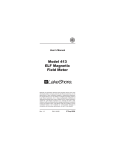
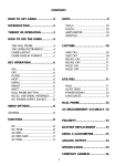
HI-3627
ELF Magnetic Field Meter
User's Manual
Copyright
© 1992 Holaday Ind. Inc.
Manual #600047 10/97
$8.50
Revision Record
Manual #600047
HI-3627 ELF Meter
Revision
--A
Description
Preliminary Release
Release
Added CE Label
Date
5/92
6/92
10/97
TABLE OF CONTENTS
1.0
Description . . . . . . . . . . . . . . . . . . . . . . . . 1
2.0
Specifications . . . . . . . . . . . . . . . . . . . . . . . 3
3.0
Operation . . . . . . . . . . . . . . . . . . . . .
Introduction . . . . . . . . . . . . . . . .
Quick Start . . . . . . . . . . . . . . . .
Controls, Indicators and Connectors
Recorder Output . . . . . . . . . . . . .
Low Battery Indication . . . . . . . . .
Recharging . . . . . . . . . . . . . . . . .
4.0
Making Measurements . . . . . . . . . . . . . . . . 11
5.0
Example Applications . . . . . . . . . . . . . . . .
Mapping Power Lines . . . . . . . . . . . . .
Locating and Mapping Underground
Cables . . . . . . . . . . . . . . . . . . . . . . .
VDTs . . . . . . . . . . . . . . . . . . . . . . .
Residential Measurement Surveys . . . .
Residential Ground Currents . . . . . . . .
Ground Faults . . . . . . . . . . . . . . . . . .
Pipe Inspections . . . . . . . . . . . . . . . .
Site Surveys . . . . . . . . . . . . . . . . . . .
....
....
....
...
....
....
....
5
5
5
5
7
8
9
13
13
14
14
15
17
17
18
18
6.0
Maintenance . . . . . . . . . . . . . . . . . . . . . . 19
Battery Replacement . . . . . . . . . . . . . 19
7.0
Principle of Operation . . . . . .
Probe . . . . . . . . . . . . .
Input Signal Conditioning
Filter Section . . . . . . . .
RMS Circuitry . . . . . . . .
Information Processing . .
Power supply . . . . . . . .
.
.
.
.
.
.
.
.
.
.
.
.
.
.
.
.
.
.
.
.
.
.
.
.
.
.
.
.
.
.
.
.
.
.
.
.
.
.
.
.
.
.
.
.
.
.
.
.
.
.
.
.
.
.
.
.
.
.
.
.
.
.
.
.
.
.
.
.
.
.
21
21
21
21
23
23
23
8.0
Calibration . . . . . . . . . . . . . . . . . . . . . . . . 25
9.0
References . . . . . . . . . . . . . . . . . . . . . . . . 27
LIMITED WARRANTY
HOLADAY INDUSTRIES, INC. WARRANTS EACH MODEL HI-3627 3AXIS ELF MAGNETIC FIELD METER BE FREE FROM DEFECTS IN
MATERIAL AND WORKMANSHIP FOR A PERIOD OF ONE YEAR FROM
DATE OF SHIPMENT TO THE PURCHASER.
THIS WARRANTY
EXTENDS TO THE ORIGINAL PURCHASER ONLY AND DOES NOT
APPLY TO BATTERIES OR ANY PRODUCT OR PARTS SUBJECT TO
MISUSE, NEGLECT, ACCIDENT, UNAUTHORIZED SERVICE OR
ABNORMAL CONDITIONS OF OPERATION.
IN THE EVENT OF INSTRUMENT FAILURE COVERED BY THIS
WARRANTY, HOLADAY INDUSTRIES, INC. WILL, WITHOUT CHARGE,
REPAIR AND RECALIBRATE THE INSTRUMENT IF RETURNED TO THEIR
FACTORY WITHIN ONE YEAR OF THE ORIGINAL PURCHASE,
PROVIDED THAT HOLADAY INDUSTRIES' EXAMINATION DISCLOSES
TO ITS SATISFACTION THAT THE PRODUCT WAS DEFECTIVE.
HOLADAY INDUSTRIES, INC. MAY, AT ITS OPTION, REPLACE THE
PRODUCT IN LIEU OF REPAIR. IF THE DEFECT WAS CAUSED BY
MISUSE, NEGLECT,
ACCIDENT, UNAUTHORIZED SERVICE OR
ABNORMAL CONDITIONS OF OPERATIONS, REPAIRS WILL BE BILLED
AT A NOMINAL COST. IN SUCH CASE, AN ESTIMATE WILL BE
PROVIDED BEFORE WORK IS STARTED IF REQUESTED BY THE
PURCHASER.
FOR WARRANTY SERVICE, CONTACT HOLADAY INDUSTRIES, INC.
GIVING FULL DETAILS OF THE FAILURE AND THE SERIAL NUMBER OF
THE INSTRUMENT. YOU WILL THEN BE GIVEN SERVICE INFORMATION
OR SHIPPING INSTRUCTIONS. RETURN THE INSTRUMENT TO THE
FACTORY TRANSPORTATION PREPAID. REPAIRS WILL BE MADE AT
THE FACTORY AND THE INSTRUMENT RETURNED TO YOU
TRANSPORTATION PAID. HOLADAY INDUSTRIES, INC. ASSUMES NO
RESPONSIBILITY FOR LOSS OF, OR DAMAGE TO, PRODUCTS IN
TRANSIT.
WARNING
SPECIAL CAUTION IS ADVISED WHEN WORKING IN ENVIRONMENTS
WHERE CONTACT WITH HIGH VOLTAGE OR HIGH CURRENT CIRCUITS
OR APPARATUS IS POSSIBLE. THIS IS PARTICULARLY TRUE WHEN
ATTEMPTING TO OBTAIN ELECTRIC OR MAGNETIC FIELD STRENGTH
MEASUREMENTS IN CONFINED QUARTERS, FOR EXAMPLE INSIDE
CABINETS CONTAINING ELECTRICALLY OPERATED EQUIPMENT,
ELECTRIC POWER SUBSTATIONS OR IN VERY CLOSE PROXIMITY TO
THE CONDUCTORS OF ENERGIZED POWER LINES. ACCIDENTAL
CONTACT WITH OBJECTS OR CIRCUITS OPERATED AT HIGH
VOLTAGES OR HIGH CURRENTS CAN BE LETHAL!
HOLADAY
INDUSTRIES, INC. ASSUMES NO LIABILITY FOR DAMAGES OR
PERSONAL INJURY WHICH MAY RESULT FROM ACCIDENTS ARISING
OUT OF USE OF THIS EQUIPMENT.
HI-3627 Manual
1.0
Page --1
Description
The HI-3627 ELF Magnetic Field Meter is designed to measure
the flux density of magnetic fields in the frequency range of 5
Hz to 2 kHz. This conforms with recent measurement guidelines
issued in Sweden for extremely-low-frequency (ELF) magnetic
fields produced by video display terminals (VDTs). The HI-3627
finds application in the measurement of magnetic fields
associated with electric power lines, electrically operated
appliances and VDTs.
The HI-3627 is a three axis flux density meter designed to be
responsive to either sinusoidal or complex magnetic field
waveforms such as produced by the vertical deflection systems
of VDTs. It computes the root-mean-square (RMS) value of
magnetic flux density and directly displays it on an analog
meter. The sensor consists of three multiturn loops connected
to the instrumentation readout package via a 1.2 meter long
cable. The microprocessor in the meter continually computes the
magnitude of the field independent of the probe orientation. This
allows quick assessment of the actual flux density value while
conveniently holding the instrument for easy meter reading. This
feature makes the HI-3627 especially useful for rapid, large area
surveys of magnetic fields.
The field sensor is electrically shielded making the response of
the HI-3627 immune to most electric field effects. No
interference is caused by ambient electric fields such as might
be found beneath high voltage, overhead electric power lines or
nearby radio or television stations.
The HI-3627 has a wide dynamic measurement range. This
provides for readings from 0.2 milligauss to 20 gauss. This large
dynamic range makes the HI-3627 convenient for measurement
of ambient residential magnetic fields as well as high level fields
found near high current carrying conductors or electrical
machinery.
Page -- 2
HI-3627 Manual
Page --3
HI-3627 Manual
2.0
Specifications
Frequency Response:
30* Hz
2000 Hz
< 30* Hz
> 2000 Hz
*
- 3 dB
- 3 dB
Falling 80 dB/decade
Falling 40 dB/decade
(Note: The frequency response is switchable to 5 Hz)
Figure 2-1
Sensor:
External, three axis multi-turn loop, with inside
diameter of 110 mm and outside diameter of 116 mm;
loop area 0.010 m2. Cable length is 1.2 meters.
Detector Response:
True RMS field indication for accurate measurement of
non-sinusoidal waveforms.
Page -- 4
HI-3627 Manual
Sensitivity:
Full scale ranges of:
2 mG
20 mG
200 mG
2G
20 G
Accuracy:
± 5 % at calibration frequency
Power:
One 9.6 volt NiCad battery
Battery life:
Approximately 30 Hrs. continuous operation
(new battery with a full charge)
Linearity:
± 2% Full Scale
The instrument is calibrated using a one meter diameter pair of
Helmholtz coils for establishing an accurately known magnetic
field flux density. A precisely controlled and measured sinusoidal
current is driven through the Helmholtz coils and, based on the
dimensions of the coils, the magnetic field flux density between
the coils is calculated.
While the HI-3627 indicates magnetic flux density (B) in units
of milligauss, the flux density in microtesla or magnetic field
strength (H) in milliamperes per meter may be obtained via the
following relations:
1 mG = .1 microtesla (:T)
1 mG = 80 milliamperes per meter (mA/m)
HI-3627 Manual
3.0
Page --5
Operation
Introduction
This section defines and describes all controls, indicators and
connectors. Refer to figure 3-1 for the location of the
components.
For experienced users or others who particularly dislike reading
explanations of operation, the following is a quick start section
that gets you up and running as quickly as possible.
Quick Start
To be brief, follow these steps:
Step 1. Plug sensor into multi-pin connector at top end of the
meter.
Step 2. Turn the meter on by rotating the range selector
switch one position clockwise. Note: the battery low
LED will flash momentarily as the meter is turned on.
Step 3.
Verify that the over range LED and the battery LED are
not illuminated.
Step 4. Make measurements with the range selector switch
set for the maximum reading without an over range
indication.
Controls, Indicators and Connectors
The HI-3627 is housed in a rugged aluminum case with a
detachable probe. The unit is shipped in a convenient carrying
case with foam cutouts which accommodate the meter, probe
and the optional accessories offered with the meter.
Page -- 6
HI-3627 Manual
Figure 3-1
The probe is detachable and consists of a sensing head
containing three coils oriented to pick up the X, Y, and Z
components of the field. The probe plugs into a multi-pin
connector at the top end of the enclosure.
There is also a 1/4 inch stereo phone jack on the end of the
case. This is used to connect the battery charger and also
provide a recorder output signal. See figure 3-1.
Two switches control the operation of the HI-3627. The rotary
selector switch turns on the instrument and selects one of five
Page --7
HI-3627 Manual
ranges for measurement. The scales are arranged so that when
the meter is first turned on, the meter will be on it's least
sensitive scale, ie. highest range. As the switch is rotated
clockwise the sensitivity of the meter increases. Generally
speaking, the readings will be most accurate when the meter
movement has maximum deflection without an over range
indication. A second toggle switch controls the desired low
frequency cutoff. The user may select the lower frequency of
the band pass for the instrument as either 30 Hz or 5 Hz.
There are two LED indicators on the front panel. A "Low
Battery" LED lights when the battery voltage is too low for
accurate readings. After lighting, the batteries will provide about
10 minutes of useful operation. The "Over Range" LED
illuminates when the field being measured exceeds the range
selected on the HI-3627.
Recorder Output
The HI-3627 Magnetic Field Meter has a recorder output. The
recorder output is a voltage signal (0-5 VDC) proportional to the
needle deflection on the meter. This output can be used to drive
a chart recorder, data logger, or other device to display the
indicated field reading on the instrument.
Figure 3-2
Page -- 8
HI-3627 Manual
The connection for the recorder output is made through the
same connector as the battery charger (refer to figure 3-2). This
is a two circuit connector (jack) that mates with a standard ¼
inch stereo phone plug. The ring of the phone plug is reserved
for battery charger input and the tip is connected to the recorder
output. The shaft of the plug is the common ground. A diode in
the battery charging circuit keeps the battery voltage from being
applied to the recorder output when a plug is inserted into the
jack.
The recorder output comes directly from the circuit driving the
meter movement. The maximum current available to the
recorder output jack is 1 milliampere (5000 ohm minimum
recorder output load). A lower impedance recorder output load
will affect the accuracy of both the meter reading and the signal
to the recorder output.
The meter movement and the recorder output are driven by a
PWM (pulse width modulator). This leads to a small amount of
ripple on the recorder output, typically 50 mV at 40 Hz.
Low Battery Indication
The HI-3627 Magnetic Field Meter includes a "Low Battery"
indicator. This is an LED mounted on the front panel (refer to
figure 3-1). It is normal for the LED indicator to briefly blink
when turning the switch to various ranges and when turning the
instrument off.
If the "Low Battery" indicator remains on during operation, the
battery must be recharged. When the "Low Battery" LED lights,
about 10 minutes of useful operation remains. This relatively
short time is due to the output voltage of a NiCad battery
remaining relatively flat until the battery is almost completely
discharged, and then dropping very rapidly.
HI-3627 Manual
Page --9
Recharging
Recharge the battery with either the standard trickle charger or
the optional HI-3102 rapid charger. Recharging a fully
discharged unit will take 15 hours with the standard trickle
charger or one hour with the rapid charger.
The standard charger provided with the HI-3627 is a trickle
charger. It works by charging the battery with relatively low
current. The charger can be left connected to the meter
indefinitely without causing severe damage, although some
memory effects may result. NiCad "memory" sometimes occurs
when the battery is kept at full or nearly full charge without
intervening discharge cycles. The effect is to reduce the
apparent capacity of the battery and shows up as a short
operating time before recharging is required. This effect can be
minimized by occasionally operating the meter until the "Low
Battery" LED indicates recharging is necessary.
Charging time can only be reduced by increasing the current into
the battery. If the higher current is not carefully monitored and
stopped at the proper time, the battery will be permanently
damaged. The optional HI-3102 battery charger has been
developed in cooperation with a NiCad cell manufacturer to
charge the NiCad battery at it's maximum rate. This charger is
microcomputer controlled, and can safely recharge the NiCad
battery pack fully in one hour. The HI-3102 charger uses a
negative delta V algorithm to determine when the battery is fully
charged allowing a battery of any discharge state to be brought
to a full charge state without being overcharged.
There are a number of chargers available for this type of NiCad
battery pack. Some do a very good job of charging the battery,
but others sacrifice battery life for charge time. The HI-3627
should be charged only with approved battery chargers.
Page -- 10
HI-3627 Manual
HI-3627 Manual
4.0
Page --11
Making Measurements
To begin making field measurements, plug the probe into the
meter. Turn the range switch to the right, increasing the
instrument's sensitivity until an upscale reading on the meter is
observed. The readings will be most accurate when maximum
deflection is observed. When an over range indication does
occur, the next larger range should be selected. It should be
noted that the meter movement is protected against deflection
past the top of scale. Therefore, the "Over Range" LED must be
relied on to indicate an over range condition.
It is not necessary to rotate the sensor to obtain a maximum
indication on the meter. The value of flux density is obtained by
taking three orthogonal measurements of the field. In this case,
the sensor has three separate coils oriented in three mutually
perpendicular directions around a fixed point. The resultant flux
density is then found by calculating the root-sum-squared value
from the individual RMS readings for each axis.
For area surveys of ELF fields, the 30 Hz cutoff will be more
useful. When the 5 Hz frequency cutoff is selected, the unit will
be sensitive to movement of the sensor. This is due to the
earth's constant magnetic field (approximately 500 mG). When
the sensor is accelerated or rotated within this constant field,
there will be an output from the sensor at a frequency
corresponding to the movement. Consequently, during such
movement, the meter will typically show significant upscale
indications. The 5 Hz frequency cutoff setting is primarily useful
for measurements at fixed coil positions such as near VDTs.
Page -- 12
HI-3627 Manual
Page --13
HI-3627 Manual
5.0
Example Applications of the HI-3627
Mapping Power Lines
Magnetic fields near power lines can be easily measured with
the HI-3627. An approach commonly used to characterize
power line fields is to measure the flux density along a straight
line which passes perpendicular to the power line. Generally,
readings are first taken along the length of a span of the power
line to identify the point at which the greatest flux density
exists. Then at this point take the readings perpendicular to the
power line. Take readings every five to ten feet. A magnetic
field flux density profile can then be developed. This method is
outlined by the Institute of Electrical and Electronics Engineers
(IEEE) in the American National Standards Institute (ANSI)
standard 644-1987 (1).
Figure 5-1
Figure 5-1 is an example of a theoretical profile obtained for a
230 kilovolt (kV), single circuit line with 1000 amperes flowing
in the conductors. For the particular case presented, the
conductors are situated 50 feet above ground and are spaced
Page -- 14
HI-3627 Manual
32 feet apart. The actual profile shape is dependent on the
exact geometry of the power line, its height above ground and
the current flowing in the line. The flux density peaks near a
point beneath the conductors of the line.
Locating and Mapping Underground Cables
The HI-3627 with its omni-directional response is an effective
and easy to use device for locating buried current carrying
bodies. The procedure is quite simple. Hold the probe near the
ground at a constant height and walk toward the highest field
reading. A peak value usually means that you are standing
above the current carrying body.
A similar approach may be used for measuring the flux density
produced by buried lines. In this case, the area must be explored
by walking about with the meter until the region of maximum
flux density is found. Then, as in mapping power lines, you
would make straight line passes perpendicular to the buried
cable recording readings at fixed intervals.
VDTs
VDTs produce ELF magnetic fields which come about from the
circuitry within the VDT which deflects the electron beam
vertically in the cathode-ray-tube (CRT). ELF fields may also be
generated by the VDT power supply. The magnetic fields are
used to deflect the beam and have a saw-tooth waveform with
frequencies ranging between approximately 45 Hz and 75 Hz,
depending on the particular design of the VDT. The HI-3627 is
designed to properly detect these magnetic fields because of its
RMS detector and wide bandwidth.
Two different methods for VDT magnetic field measurements
have been commonly used. The first is that of characterizing the
field at a fixed distance from the screen of the VDT.
Conventionally, distances of 30 cm and 50 cm have been used
for such measurements. Normally, the measurements are taken
from the front surface of the screen. Additional measurements
HI-3627 Manual
Page --15
may be taken relative to the sides, the top and the back of the
VDT to explore the distribution of the fields about the VDT.
The second method involves a measurement at the position of
the VDT operator to assess the flux density to which the
operator is actually exposed while sitting at the VDT. Because
different individuals will sit at different locations and have
different postures, the operator exposure measurement may be
more a function of the operator than of the specific VDT. A
reasonable approach for the operator exposure measurement is
to position the sensor at a point corresponding to where the
center of the body would be located during operation of the
VDT.
It is important to note that the magnetic fields decrease very
rapidly with increasing distance from the screen. Because of this
characteristic, it is important to insure that the position of the
sensor is precisely known. Attempts to repeat the measurement
results will be hampered by unnecessary variability if the sensor
is not replaced at the same exact position. Spacing
measurements should be made from the VDT surface to the
center of the sensor.
The Model HI-3627 contains circuitry to extend the lower
frequency response down to 5 Hz in accordance with
recommendations used for VDT measurements according to the
guidelines issued in Sweden for extremely-low-frequency (ELF)
magnetic fields produced by video display terminals (VDTs). The
user is referred to the Swedish specifications for measurement
(2) for application details.
Residential Measurement Surveys
Magnetic fields found in home environments are highly variable,
depending on location within the home. This variability is
strongly related to the distribution of the wiring in the home, the
location of electrical appliances and, sometimes, the location of
plumbing lines or other metallic structures within the ground
which may form low resistance paths for electrical ground
Page -- 16
HI-3627 Manual
return currents. Establishing what the ambient magnetic field
environment is in a home usually requires numerous
measurements throughout the home, with at least one
measurement within each room. Normal practice would include
at least one field measurement taken near the center of each
room. A more thorough approach would include five
measurements in each room, one at the center and one near
each corner of the room. A reasonable technique is to position
the sensor at a point approximately one meter from each room
corner for the flux density measurement. This avoids, to an
extent, placing the sensor immediately next to wiring which
may be hidden within the walls of the room and which may
yield unrealistically high values of flux density compared to what
most individuals within the room might be exposed. A possible
protocol for making the measurements is outlined in the
California Department of Health Services paper on suggested
protocol for measuring 60 Hz magnetic fields in residences (3).
Surveys of the areas near electrical appliances will usually reveal
higher values of flux density due to the currents flowing within
motors or heating elements. This may influence the location of
beds, and other locations of extended occupancy. In
characterizing the magnetic fields near obvious sources, such as
appliances, it is often helpful to measure and record the flux
density value at intervals of a few inches (or centimeters)
beginning near the surface of the device. These data will help
provide a perspective on the spatial extent of the elevated field
levels and the significance of the levels relative to other values
determined elsewhere within the home. Field measurements
should take into account the likelihood that individuals may have
access to areas where measurements are contemplated.
Because 60 Hz magnetic fields produced by the use of
electricity within the home are dependent on the magnitude of
current flowing within wires or the operation of appliances, flux
densities will be seen to vary with time, being greater when
more electrical power is being used. For example, when heating
or air conditioning systems turn on or the compressor within a
refrigerator cycles on, the flux density will increase.
HI-3627 Manual
Page --17
Measurements must take this condition into account. It is
recommended when taking measurements in a room, the meter
be watched for a period of time to observe for fluctuations in
the indicated value of flux density. After some experience, it
may be possible to relate the observed fluctuations to various
uses of electricity within the home.
Residential Ground Currents
A phenomenon, which recently received attention in regard to
residential magnetic fields, is the flow of earth currents via
plumbing lines or telephone cables buried beneath the home. In
some cases, it has been noted that 60 Hz magnetic fields exist
within a home, even when the home is not using any electrical
power (the circuit breakers have all been turned off at the main
electrical service box of the home).
This observation has, in some cases, been related to the flow of
currents beneath the home on pipes or cables. It is not unusual
for currents related to other neighbors' use of electricity to flow
back to the electrical supply via low resistance paths. These are
formed by metal plumbing pipes or wires used for telephones as
opposed to the electrical system neutral wire. In such cases, it
is possible to measure magnetic flux densities within the home
even though the power to the home has been shut off.
Ground Faults
As mentioned earlier, current can exist in pipes and heating
ducts or anything metal in the house. This gives rise to an
interesting application for the HI-3627; detecting leakage
currents from appliances. For example it was noted that the
fields around a water pipe leading from a dishwasher changed
dramatically when the dishwasher was run. It was later found
that the dishwasher was defective and allowed excessive
ground currents to flow. The same principles apply to industrial
and power distribution situations.
Page -- 18
HI-3627 Manual
Pipe Inspections
It was noted that the buried pipes leading to fire hydrants
tended to concentrate the currents flowing in the ground from
power distribution leakages. The field from this current could be
detected and measured. It was also noted that the field would
vary uniformly as the operator walked along the pipe. The field
would, however, exhibit significant variations at points on the
pipe where there was a break or a large amount of corrosion. In
this way a single operator with very little equipment could
inspect a large section of pipe for possible failures in a very
short period of time. This, of course, is a singular example that
only worked because of very unusual circumstances, but it does
show the versatility of this easy to use field meter.
Site Surveys
Site surveys are another useful application. This example was
in an office with several CRT terminals. It was found that
several times a day the images on the screens would start to
move in a waving fashion. It was discovered by surveying the
room that a power distribution cable for an industrial user was
routed near the room. The cable was moved and the problem
went away.
Page --19
HI-3627 Manual
6.0
Maintenance
Battery Replacement
The battery pack used in the HI-3627 Magnetic Field meter is a
commonly available NiCad battery pack (Holaday part #
491044, 9.6 Volt, 600 mA-H, or equivalent). In the event of
battery failure, a new battery can be obtained from Holaday
Industries or from a local source.
The battery pack is replaced by removing the back cover of the
meter, unplugging the battery, and removing the battery
retainer. Replace the battery pack by reversing these steps. The
back cover is fastened by six screws that can be found around
the lip if the front panel. The battery is retained by two more
screws and a metal strap that holds the battery in place (a #1
Phillips screw driver will work well for these operations).
CAUTION
Never short the output of a NiCad battery
(even a discharged battery). The resultant
currents will be large. This will cause the
lead wires to become extremely hot which
can cause severe burns and/or fire.
Page -- 20
HI-3627 Manual
HI-3627 Manual
7.0
Page --21
Principle of Operation
The circuitry of the HI-3627 can be divided into six sections;
the probe, input signal conditioning, filter section, RMS
calculation, information processing and power supply. Each of
these is discussed in the follow sections (see Figure 7-1).
Probe
The probe consists of three concentric shielded coils aligned
with their axes perpendicular to one another. The electrostatic
shield of each coil is isolated from that of the other. The shields
are connected together at a single point at the base of the
sphere defined by the coils. The signals from each coil are
brought to the meter through a shielded twisted pair cable with
its shield connected to the coil shield common point.
Input Signal Conditioning
The output voltage of a coil varies with the frequency of the
applied magnetic field. A single pole low pass filter is added to
the output of each coil to flatten the frequency response and
provide impedance matching. The input signals are then passed
through a programmable gain amplifier stage that provides the
necessary amplification for the individual ranges. The signals
then pass to the filter section.
Filter Section
Each channel is filtered separately. The first stage is a two pole
Butterworth low pass filter at 2000 Hz. A Butterworth filter
attenuates the signal by 3 dB at the cutoff frequency with
attenuation in the stop band and no ripple in the pass band. The
output of the low pass filter is fed into two 4 pole high pass
filters. The cutoff frequencies on these filters are 5 Hz and 30
Hz corresponding to the low frequency cutoff selections.
Page -- 22
HI-3627 Manual
HI-3627 Manual
Page --23
The front panel switch controls an analog multiplexer which
selects the proper filter output.
RMS Circuitry
The signal from each filter is fed into one of three true RMS
converter integrated circuits, one for each channel. The time
response of the RMS converter is selected to give acceptable
step input response time while yielding minimal RMS conversion
errors at 5 Hz. This time constant is around 500 msec. This is
the predominant time constant of the meter.
Information Processing
The outputs of the three true RMS converters are combined
through vector addition to calculate the resultant field
magnitude. This computation is computed by a processor and an
A/D converter. The meter is driven by outputs configured as a
PWM (Pulse Width Modulator). The processor performs an A/D
conversion on the signal from each axis by programming an
analog multiplexer into a 12 bit A/D converter. The digital values
are then squared, summed and the square root of the sum is
calculated. This result is used to set the duty cycle of the PWM
output which drives the meter movement. The output frequency
of the PWM is about 30 Hz. This frequency is too high to show
on the analog meter, but can be detected as about 50 mV of
ripple on the recorder output.
Power supply
Power is supplied to the HI-3627 by a NiCad battery. The NiCad
battery chosen for this application is a common type. The
current consumption of the instrument is relatively low with the
operating life being greater than 30 hours of continuous
operation. During typical daily operation, with intermittent use,
the time between recharges will be greater. The individual
voltages supplied to the circuitry are derived from the battery
voltage directly, supplied through series pass regulators and
from a switched capacitor voltage invertor.
Page -- 24
HI-3627 Manual
HI-3627 Manual
8.0
Page --25
Calibration
The HI-3627 is calibrated using a one meter diameter Helmholtz
coil. Each axis is individually calibrated. Calibration is performed
at 60 Hz at levels of 200 mG and 2 G. All calibrations are
traceable to NIST. The frequency response of each axis is
checked in all meters.
The recommended recalibration interval is one year. Holaday
Industries offers complete recalibration services which comply
with MIL-STD 45662A.
Page -- 26
HI-3627 Manual
HI-3627 Manual
9.0
Page --27
References
(1) IEEE Standard Procedures for Measurement of Power
Frequency Electric and Magnetic Fields from AC Power Lines.
ANSI/IEEE standard 644-1987. Published by The Institute of
Electrical and Electronics Engineers, Inc., 345 East 47th Street,
New York, NY 10017. Approved November 17, 1986.
(2) Swedish National Board for Measurement and Testing, Test
Methods for Visual Display Units- Visual Ergonomics and
Emission Characteristics. MPR 1990:8, 1990-12-01, National
Board for Measurement and Testing, Box 878, S-501 15 Bors,
Sweden.
(3) Electric and Magnetic Field Measurements and Possible
Effects on Human Health from Appliances, Power Lines, and
Other Common Sources. Special Epidemiological Studies
Program, California Department of Health Services, 2151
Berkeley Way, Room 704, Berkeley, Ca. 94704 (415)540-2669
Page -- 28
HI-3627 Manual
--NOTES--