1
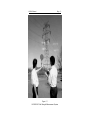
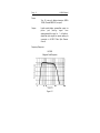
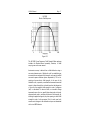
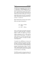
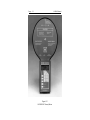
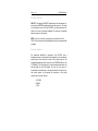
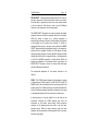
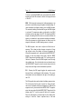
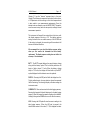
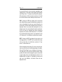
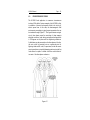
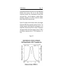
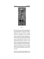
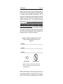
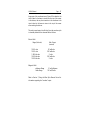
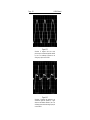
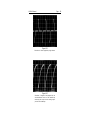
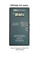
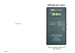
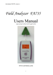
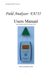
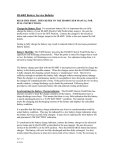
HI-3604
ELF Survey Meter
User's Manual
Copyright
Manual #600043B 6/97
© 1992 Holaday Ind. Inc.
$12.50
Revision Record
Manual # 600043
HI-3604 Survey Meter
Revision
--A
B
Description
Release
New LCD
Added CE Label
Date
8/92
12/92
6/97
TABLE OF CONTENTS
1.0
DESCRIPTION . . . . . . . . . . . . . . . . . . . . . . . . .
1
2.0
SPECIFICATIONS . . . . . . . . . . . . . . . . . . . . . . . . 4
3.0
OPERATION . . . . . . . . . . . . . . . . . . .
Start Up . . . . . . . . . . . . . . . . . .
Digital Display . . . . . . . . . . . . . .
Electric Field/Magnetic Field Mode
Selection . . . . . . . . . . . . . . . . .
Keypad Inputs . . . . . . . . . . . . . .
Keypad Matrix . . . . . . . . . . . . . .
.......
.......
.......
11
11
13
.......
.......
.......
13
14
14
4.0
POWER FREQUENCY FIELDS . . . . . . . . . . . . . . .
19
5.0
EXAMPLE APPLICATIONS . . . . . .
Field Strength Measurements
Waveform Measurements . .
Frequency Measurements . .
.
.
.
.
23
23
26
30
6.0
MAINTENANCE . . . . . . . . . . . . . . . . . . . . . . . .
Battery Replacement . . . . . . . . . . . . . . . . .
31
31
7.0
USING THE HI-3616 FIBER OPTIC REMOTE
CONTROL . . . . . . . . . . . . . . . . . . . . . . . . . . . .
Turn-on Procedure When Using
the HI-3616 . . . . . . . . . . . . . . . . . . . . . .
.
.
.
.
.
.
.
.
.
.
.
.
.
.
.
.
.
.
.
.
.
.
.
.
.
.
.
.
.
.
.
.
.
.
.
.
.
.
.
.
33
33
LIMITED WARRANTY
HOLADAY INDUSTRIES, INC. WARRANTS EACH MODEL HI-3604 ELF
SURVEY METER TO BE FREE FROM DEFECTS IN MATERIAL AND
WORKMANSHIP FOR A PERIOD OF ONE YEAR FROM DATE OF SHIPMENT
TO THE PURCHASER. THIS WARRANTY EXTENDS TO THE ORIGINAL
PURCHASER ONLY AND DOES NOT APPLY TO BATTERIES OR ANY
PRODUCT OR PARTS SUBJECT TO MISUSE, NEGLECT, ACCIDENT,
UNAUTHORIZED SERVICE OR ABNORMAL CONDITIONS OF OPERATION.
IN THE EVENT OF INSTRUMENT FAILURE COVERED BY THIS WARRANTY,
HOLADAY INDUSTRIES, INC. WILL, WITHOUT CHARGE, REPAIR AND
RECALIBRATE THE INSTRUMENT IF RETURNED TO THEIR FACTORY WITHIN
ONE YEAR OF THE ORIGINAL PURCHASE, PROVIDED THAT HOLADAY
INDUSTRIES' EXAMINATION DISCLOSES TO ITS SATISFACTION THAT THE
PRODUCT WAS DEFECTIVE. HOLADAY INDUSTRIES, INC. MAY, AT ITS
OPTION, REPLACE THE PRODUCT IN LIEU OF REPAIR. IF THE DEFECT
WAS CAUSED BY MISUSE, NEGLECT, ACCIDENT, UNAUTHORIZED
SERVICE OR ABNORMAL CONDITIONS OF OPERATIONS, REPAIRS WILL BE
BILLED AT A NOMINAL COST. IN SUCH CASE, AN ESTIMATE WILL BE
PROVIDED BEFORE WORK IS STARTED IF REQUESTED BY THE
PURCHASER.
FOR WARRANTY SERVICE, CONTACT HOLADAY INDUSTRIES, INC.
GIVING FULL DETAILS OF THE FAILURE AND THE SERIAL NUMBER OF THE
INSTRUMENT. YOU WILL THEN BE GIVEN SERVICE INFORMATION OR
SHIPPING INSTRUCTIONS. RETURN THE INSTRUMENT TO THE FACTORY
TRANSPORTATION PREPAID. REPAIRS WILL BE MADE AT THE FACTORY
AND THE INSTRUMENT RETURNED TO YOU TRANSPORTATION PAID.
HOLADAY INDUSTRIES, INC. ASSUMES NO RESPONSIBILITY FOR LOSS OF,
OR DAMAGE TO, PRODUCTS IN TRANSIT.
WARNING
SPECIAL CAUTION IS ADVISED WHEN WORKING IN ENVIRONMENTS
WHERE CONTACT WITH HIGH VOLTAGE OR HIGH CURRENT CIRCUITS OR
APPARATUS IS POSSIBLE.
THIS IS PARTICULARLY TRUE WHEN
ATTEMPTING TO OBTAIN ELECTRIC OR MAGNETIC FIELD STRENGTH
MEASUREMENTS IN CONFINED QUARTERS, FOR EXAMPLE INSIDE
CABINETS CONTAINING ELECTRICALLY OPERATED EQUIPMENT, ELECTRIC
POWER SUBSTATIONS OR IN VERY CLOSE PROXIMITY TO THE
CONDUCTORS OF ENERGIZED POWER LINES. ACCIDENTAL CONTACT
WITH OBJECTS OR CIRCUITS OPERATED AT HIGH VOLTAGES OR HIGH
CURRENTS CAN BE LETHAL! HOLADAY INDUSTRIES, INC. ASSUMES NO
LIABILITY FOR DAMAGES OR PERSONAL INJURY WHICH MAY RESULT
FROM ACCIDENTS ARISING OUT OF USE OF THIS EQUIPMENT.
HI-3604 Manual
1.0
Page -- 1
DESCRIPTION
The HI-3604 Power Frequency Field Strength Measurement
System is designed to assist in the evaluation of electric and
magnetic fields that are associated with 50/60-Hz electric
power transmission and distribution lines along with electrically
operated equipment and appliances. Direct digital readout of
field strength is provided by the instrument with the ability to
read the meter remotely via a special fiber optic remote control
(Model HI-3616) which is available as an option. The HI-3604
finds applications in research and environmental field studies
where knowledge of the strength of power frequency fields is
required. It is designed to provide engineers, industrial hygienists
and health and safety personnel with a sophisticated tool for the
accurate investigation of power frequency electrical
environments.
The HI-3604 has two switch selectable sensors for measuring
both electric and magnetic fields (see Figure 1-1). The
instruments' capabilities include datalogging, waveform output,
full auto-ranging, and a custom Liquid Crystal Display (LCD)
with a bar graph, as standard features. All selection and control
functions are input from a front panel membrane switch pad.
True RMS detection assures accurate measurements of complex
waveforms. The waveform output jack allows observation and
evaluation of the actual waveform being measured. The
datalogger feature captures up to 112 field readings for later
review using front panel controls. Microprocessor technology is
incorporated in the HI-3604 to provide for automatic range
changing (manual range changing may be selected) and
automatic zeroing of the instrument.
Electric fields are detected by a displacement current sensor
which consists of two thinly separated conductive disks which
are connected together electrically. When immersed in an
electric field, charge is redistributed among the two parallel
disks such that the electric field between the two disks remains
at zero. This redistribution of charge is reflected as a
displacement current which can be measured and subsequently,
Page -- 2
HI-3604 Manual
related to the external electric field strength. This type of
transducer possesses a flat frequency response and permits
accurate measurement of fields having significant harmonic
content with energy at frequencies above the fundamental of 50
or 60-Hz.
Surrounding the circular displacement current sensing disks is a
coil consisting of several hundred turns of fine gage wire. When
placed in an alternating magnetic field, a current is induced in
the coil which is proportional to the strength of the applied
magnetic field. Magnetic field strength is then determined by
measuring the voltage developed across the terminals of the
coil. While an unterminated loop will provide an output which is
directly proportional to the frequency of the magnetic field, the
HI-3604 employs electronic compensation circuitry which
results in a tailored frequency response that is flat in the
frequency range of importance to power frequency
measurements. This feature permits the HI- 3604 to be used in
environments having significant harmonic content and yield
accurate measures of the resultant fields. Broadband response
is required when measuring fields having significant harmonic
distortion such as may occur with electrical machinery.
The outputs of both field transducers are measured with a true
root-mean-square (RMS) detector. True RMS detection offers
accurate evaluation of fields having a variety of waveforms,
including non-sinusoidal waveforms. Thus, whether the field
being measured is produced by a near pure sine wave source,
like an electric power transmission line, or a highly nonsinusoidal source, like a solid state light dimmer, the HI-3604
will yield consistent measures of the RMS field strengths.
HI-3604 Manual
Page -- 3
Figure 1-1
HI-3604 ELF Field Strength Measurement System
Page -- 4
HI-3604 Manual
HI-3604 Manual
2.0
Page -- 5
SPECIFICATIONS
Sensors:
Concentric plate displacement current electric
field sensors
6.5 inch (16.5 cm) diameter 400 turn
electrically shielded magnetic field sensing coil
Switch selectable
magnetic fields
Sensitivity:
Features:
between
electric
and
Electric fields, 1 V/m - 199 kV/m
Magnetic fields, 0.1 mG - 20 G
All function and range selection changes are
made by use of the membrane switch keypads
on the front panel. Internal electronic range
switching allows full auto-ranging on either the
Electric or Magnetic field functions.
Max-hold feature stores and displays highest
reading
Amplitude Response:
True RMS field strength measurement for
accurate measurement of non-sinusoidal
waveforms
Polarization Response:
Displacement sensor and magnetic field sensor
are designed for response to one field
polarization component at a time
Page -- 6
Power:
Output:
HI-3604 Manual
Two (2) nine-volt alkaline batteries (NEDA
1604A, Duracell MN1604, or equal)
Liquid crystal display; preamplifier output via
phono
jack
(analog
signal
from
sensor/preamplifier equal to 1 mV/(mA/m);
digital fiber optic signal (for remote reading via
connection to HI-3616 Fiber Optic Remote
Control)
Frequency Response:
HI-3604
Magnetic Field Response
Figure 2-1
HI-3604 Manual
Page -- 7
HI-3604
Electric Field Response
Figure 2-2
The HI-3604 Power Frequency Field Strength Meter package
includes the Readout-Sensor assembly, batteries, a fitted
carrying case and a user manual.
Instrument accuracy is derived from a field calibration using a
one meter diameter pair of Helmholtz coils for establishing an
accurately known magnetic field strength, and a pair of parallel
one-meter square aluminum plates separated by 30 cm for
creating a known electric field strength. In the case of the
Helmholtz coils, a precisely controlled and measured sinusoidal
current is driven through the coils and, based on the dimensions
of the coils, the magnetic field strength in units of milligauss
(mG) is calculated. For electric fields, a sinusoidal voltage
impressed across the two parallel plate electrodes is directly
measured and used to calculate the electric field strength by
dividing the applied voltage by the plate spacing to obtain field
strength in units of volts per meter (V/m). In each case, both
currents and voltages in the calibration set-ups are determined
with a true RMS detector.
Page -- 8
HI-3604 Manual
The HI-3604 can be user programmed to indicate in either units
of milligauss/gauss, milliamperes/amperes per meter, or
nano/micro teslas. Refer to section 3.0 OPERATION for further
details. The HI-3604 indicates magnetic field flux density in
units of millgauss (mG) and gauss (G). Most ELF reports and
research in the US today use these units. The SI unit of
magnetic field flux density is the tesla (T). Environmental ELF
magnetic field measurements are generally reported in units of
microtesla (:T) or nanotesla (nT).
Magnetic field measurements in free space may be converted to
different units through the following relations:
1 mG = 1000 :G = 80 mA/m
1 T = 10000 G
1 mT = 1000 :T = 800 A/m
Figures 2-1 and 2-2 illustrate typical frequency response plots
for electric and magnetic field strength. The HI-3604 is
designed to provide a flat response over the range of
frequencies corresponding to the 50 or 60-Hz power line
frequency and the first several harmonics. The tailored lowfrequency characteristic to the response helps reduce magnetic
field response to movement of the sensor in the earth's
constant magnetic field.
The bandwidth of the true RMS detector is a function of the
amplitude of the applied field. The bandwidth of the HI-3604 is
also related to the particular measurement range selected.
Thus, for a specific measurement, the bandwidth exhibited may
be greater or lesser than shown in Figures 2-1 and 2-2.
Generally, maximum bandwidth, and thus accuracy, is obtained
for any given field strength by selecting the lowest range (and
scale) that still permits an on-scale reading.
The HI-3604 also provides for monitoring the waveform of the
signal coming from the sensor preamplifier circuit in the input
HI-3604 Manual
Page -- 9
module. This signal is available from the phone jack located at
the bottom of the instrument.Connection of an oscilloscope to
this jack will allow observation of the preamplifier output.
Page -- 10
HI-3604 Manual
HI-3604 Manual
3.0
Page -- 11
OPERATION
NOTE: The HI-3604 is enclosed in a rugged aluminum extruded
case for protection of its internal circuitry. Because of the
nature of its intended use, the field sensor extends from the
readout module. The structure of the sensor is a multilayered
printed circuit board. It is well secured internally to the
aluminum case and has a tough polyester covering but is
exposed to greater potential for physical damage because of its
size and location. Use care in handling the HI-3604 to avoid
damaging the sensor by striking it against objects or applying
excessive force to the sensor paddle. When not in use, keep the
HI-3604 in its protective case where the sensor paddle is
properly supported.
Start Up
Membrane switches are used for controlling the HI-3604's
operation. The switch keypads are activated by gently pressing
on the center of the pad with a finger tip. Do not use hard or
pointed objects to operate the switch keypads.
Turn the unit ON, the default measurement condition is
Magnetic Fields. The custom LCD readout displays the units of
measure in addition to the observed value. A Bargraph display
is provided along the top of the LCD window. This display is an
analog approximation of the currently displayed digital value as
a percentage of the full scale range. The Bargraph input is
unfiltered for fast response when searching for peak fields.
The digital display response is digitally filtered for increased ease
of operation. This smooths the response to rapidly changing
fields. In some measurement situations, however, it may be
helpful to increase the response of the digital display, ie. reduce
the response time. This is done when the instrument is turned
on. Refer to KEYPAD MATRIX in this section, and the operation
of the E/H keypad for details.
Page -- 12
HI-3604 Manual
Figure 3-1
HI-3604 ELF Survey Meter
HI-3604 Manual
Page -- 13
Figure 3-2
The default display response filter is F-2 (refer to KEYPAD
MATRIX in this section for more information). The instrument
will normally be received from the factory with this setting (F2). The display response setting is stored in the non-volatile
memory of the HI-3604 and if the setting is changed, the new
setting will be saved and will become the default condition. For
this reason, we recommend that you check the display response
setting when you first receive the instrument and after battery
replacement. The display response setting does not affect the
accuracy of the instrument.
The battery condition is indicated by a small "battery" symbol
in the lower left corner of the LCD. As the battery voltage
decreases, the low battery symbol begins to blink. If the battery
condition is allowed to drop below that necessary for proper
operation, the display will go blank.
Digital Display
The HI-3604 uses a custom Liquid Crystal Display to provide
information on instrument setting as well as the variables being
measured. Refer to Figure 3-2 for the display outline.
Electric Field/Magnetic Field Mode Selection
The HI-3604 measures both electric (E) and magnetic (H) fields.
The unit is switched between the E and H field modes using the
membrane switch panel keypads. The units being measured are
shown on the LCD display.
Page -- 14
HI-3604 Manual
Keypad Inputs
ON/OFF - Pressing the ON/OFF keypad turns the instrument on;
pressing the ON/OFF keypad again turns the meter off. As there
is no automatic turn off on the HI-3604, turn the instrument off
when not in use or between readings. No warm up is required
before using the instrument.
ZERO - No zero function is required or provided on the HI3604. The instrument will immediately show the measured field
strength.
Keypad Matrix
For maximum flexibility in operation, the HI-3604 has a
keyboard matrix for the upper three keypads on the membrane
switch panel. The function of each of the three keys can be
changed depending on the location of the CURSOR block in the
LCD display. The cursor block is a dark rectangle located at the
bottom edge of the LCD display. On turn on, the cursor is
located above the leftmost of the three columns of functions on
the control panel. In this mode the functions of the three
topmost keys are as follows:
A. SCALE
B. MAX
C. E/H
HI-3604 Manual
Page -- 15
MODE SELECT - Pressing the mode keypad moves the cursor to
the right; each push of the pad moves the cursor one position.
From the third, or rightmost, position, the cursor moves around
to the first position. This allows a total of nine (9) different
functions to be assigned to the three keypads.
The MODE SELECT keypad is also used to change the display
response filters as well as the magnetic field units of measure.
When the meter is turned on, a self-test procedure is
automatically performed. As part of this procedure, all segments
of the display are lit for about two seconds. To review or
change the filter and unit settings, press and hold the MODE
SELECT keypad while all the segments are lit. In this mode two
settings can be changed. Pressing the E/H keypad will step
through the filter settings. Pressing the MAX keypad will step
through the H-field units of measure. Refer to the descriptions
of the E/H and MAX keypads for further details. When the
settings are adjusted to the desired values, again press the
MODE SELECT keypad to leave the setup mode and begin
normal measurement operation.
The operational description of the various functions is as
follows:
SCALE - The SCALE keypad changes the fixed ranges or scales
of the instrument. When turned on, the HI-3604 is in the AUTO
RANGE mode. The unit determines the correct range within the
current mode (E or H field) according to the detected field level.
As the field being measured increases or decreases, the range
is automatically selected for best resolution and accuracy.
In some situations, it may be helpful to fix the scale of the
instrument. Pressing the SCALE keypad once fixes the
instrument on the current scale setting. Each successive
operation of the keypad moves the scale to the next least
sensitive range. When the least sensitive scale has been
selected, the next operation of the keypad will shift to the most
sensitive range again.
Page -- 16
HI-3604 Manual
To return to the AUTO RANGE mode, press and hold the SCALE
keypad until the AUTO indication is shown in the upper left area
of the LCD.
MAX - While using the instrument for field measurements, the
processor is continually saving the highest indicated reading. To
recall and display the highest reading, press the MAX keypad.
This maximum reading is indicated as long as the MAX keypad
is activated. The maximum reading is indicated by the MAX
indication near the right edge of the LCD. On releasing the MAX
keypad, the reading is held for about two seconds and then the
memory is cleared and a new maximum reading accumulated.
When the instrument is shifted between the electric and the
magnetic field mode, the MAX reading memory is cleared.
The MAX keypad is also used to adjust the H-field units of
measure. This is done just after the meter is turned on. During
the self-test routine, the display will show all segments lit.
When all the segments are lit, press and hold the MODE SELECT
keypad to enter the display setup mode. Hold the MODE
SELECT keypad until the display reads "F-#" and the current Hfield unit of measure. Press the MAX keypad to scroll through
the available units. Once the desired units are selected, press
the MODE SELECT keypad to save the current setup, leave the
setup mode, and begin normal measurement operation.
E/H - Pressing the E/H keypad toggles the operation mode
between Electric and Magnetic field indications. The current
measurement units are displayed to the right of the reading on
the LCD.
The E/H keypad is also used to adjust the display response time.
This is done just after the meter is turned on. During the selftest routine, the display will show all segments lit. When all the
segments are lit, press and hold the MODE SELECT keypad to
enter the setup mode. Hold the MODE SELECT keypad until the
display reads "F-#" and the current H-field unit of measure.
Press the E/H keypad to scroll through the four display filter
settings. F-4 has the "fastest" response time, ie. the least
HI-3604 Manual
Page -- 17
filtering. F-1 has the "slowest" response time, ie. the most
filtering. The difference in response from level to level is a factor
of 2. Experiment with the settings to find which response level
is best suited to your measurement requirements. Once the
desired units are selected, press the MODE SELECT keypad to
save the current setup, leave the setup mode, and begin normal
measurement operation.
The instrument will normally be received from the factory with
the display response filter set at F-2. The display response
setting is stored in the non-volatile memory of the HI-3604 and
if the setting is changed, the new setting will be saved and will
become the default condition.
We recommend that you check the display response setting
when you first receive the instrument and after battery
replacement. The display response setting does not affect the
accuracy of the instrument.
BATT - The BATT keypad displays the supply battery voltage
along with the battery symbol. The low battery indication will
begin to flash at about 7.5 volts. When the battery voltage
drops to 7.25 volts, the display will blank with only the BATT
symbol displayed and the batteries must be replaced.
DISP 3/4 - Pressing the DISP pad will shift the display from 4 to
3 digits and back again. In some situations where the measured
field is fluctuating, the three digit display will make reading the
instrument easier.
CLEAR DATA - Clears values stored in the data logging memory.
Pressing this keypad will clear all data stored in the data logging
memory. When the keypad is pressed a flashing clr is indicated.
Holding the keypad until 000 is shown will clear the memory.
LOG - Pressing the LOG pad will store the current reading in the
data logging memory. When the LOG pad is pressed, the
identification number of the value (1-112) is displayed for about
Page -- 18
HI-3604 Manual
one second followed by the stored value. Immediately upon
releasing the key, a new value may be logged by again pressing
the LOG pad. Up to 112 values can be stored in this memory.
When the memory is filled, successive operations of the LOG
key will store the most current reading in memory location 112.
PREV - Pressing the PREV key displays the last stored data
value. When the key is pressed, the identification number of the
value is first displayed for about one second followed by the
stored value. The stored value is displayed as long as the key is
depressed. About two seconds after releasing the key, the
display returns to the current reading. Successive operations of
the key will move the displayed value down towards the
beginning of the memory (value identification #1). If the PREV
key is operated while viewing value #1, the identification value
will "wrap around" to the highest stored identification number.
NEXT - Pressing the NEXT key displays the next value in the
data logging memory. If the NEXT key is operated while viewing
the last stored value, the identification number will "wrap
around" to value number one.
When the displayed value is below 5% of the current full scale,
the arrow at the left end of the BarGraph display will indicate.
When the "Below Range" arrow is indicating, the accuracy of
the reading may not be within the specified tolerance. When
possible, the scale should be changed to permit a normal field
strength reading without the "Below Range" indication. If the
displayed value is too high the " Over Range", the arrow at the
right end of the BarGraph, will indicate. Select the next
appropriate scale.
HI-3604 Manual
4.0
Page -- 19
POWER FREQUENCY FIELDS
The HI-3604 finds application in numerous circumstances
involving 60-Hz fields. A prime example of the HI-3604's utility
is evaluation of electric and magnetic fields in the vicinity of
electric power lines. In this case, the electromagnetic field
environment surrounding a typical power transmission line can
be visualized through Figure 4-1. This figure illustrates a singlecircuit, three phase power line consisting of three separate
electrical conductors, each having an impressed voltage which
is 120 degrees out of phase with its neighboring conductors.
A shield wire may be present above the three phases of the line;
this wire, which is grounded, acts as a preferred point for
lightning strikes which could, if unprotected, strike the current
carrying conductors, potentially damaging and removing the line
from service for repairs. A double circuit line would consist of
two sets of the three phase conductors.
Figure 4-1
Page -- 20
HI-3604 Manual
Electric and magnetic fields produced by the power line originate
because of the voltages impressed on the conductors and the
magnitude of current (electricity) flowing through the
conductors. Figure 6 depicts the approximate spatial orientation
of these fields; electric field lines are shown to be directed such
that they terminate at perpendicular angles to the earth's
surface and magnetic field lines are shown as lines encircling the
conductors. At any particular point in space, the field can be
determined by the superposition of the fields associated with
each conductor; because the voltage and current of each
conductor is out of phase with that in any of the others, and the
conductors have some finite spacing between them, the
resulting electric and magnetic fields are calculated on the basis
of the vector sum of fields caused by each of the three
conductors. At some points the fields can constructively add
together causing a relatively elevated field strength. At other
points the fields from the conductors may destructively add
leading to minima in the fields. Thus, power line fields can have
rather complex spatial distributions about the line. Figure 4-2
illustrates this field distribution for a typical 345 kV transmission
line carrying 1000 A. In this figure the field strengths have been
computed for a height of one meter above the ground from one
side of the line to the other.
In addition to the normal variation in field strength which is
observed along a line transverse to the power line, electric fields
beneath power lines are perturbed by the local surroundings.
Figure 4-1 illustrates the phenomenon of electric field
concentration which occurs above the head of a person standing
under the line. Because electric field lines have a tendency to
terminate on grounded objects, and because the human body is
conductive and is electrically near ground potential, there tends
to be a concentration of field lines at the top of the head. This
same phenomenon occurs with virtually any grounded object
immersed in the electric field environment of a power line and
can be confirmed via field measurements. A similar perturbation
of the magnetic field does not occur because the body is nonmagnetic. Figure 4-1 also suggests that the electric field lines
which terminate on the earth are essentially purely vertically
HI-3604 Manual
Page -- 21
oriented directly beneath the conductors but at extended lateral
distances from the line, there can be some horizontal
component to the field. Thus, in measurements of electric fields
near power lines, it may be important to explore different
polarization components of the field to assess the resultant
electric fields at points above the earth.
Figure 4-2 indicates that the maximum electric field strength
beneath the 345 kV line is expected to be about 3.4 kV/m. The
maximum magnetic field strength will be dependent on the
magnitude of current flowing in the line; Figure 4-2 represents
the magnetic fields if the line was carrying a current of 1000 A
and indicates a maximum value of 175 mG (equivalent to 14
A/m).
Figure 4-2
Page -- 22
HI-3604 Manual
HI-3604 Manual
5.0
Page -- 23
EXAMPLE APPLICATIONS
Caution - Use care when using this instrument near energized
conductors. Be sure to read the hazard warning located on the
Warranty page.
Field Strength Measurements
Measurement of electric field strength, under a power line or
near any other source of electric fields, may be accomplished by
supporting the HI-3604 on a non-conductive tripod (Part Number
491009), such as that shown in figure 5-1. Be sure to orient
the top surface of the sensor paddle towards the field source.
It is critical that the user not hold the instrument since this will
significantly alter the response of the HI-3604 providing an
apparently enlarged field collecting surface for the displacement
current sensor, resulting in an erroneously high indicated field
strength. In addition, the presence of the operator's body will
tend to perturb the electric field that is being measured. The
operator should remain approximately one to two times their
height away from the HI-3604 and observe the readings via the
use of the HI-3616 Fiber Optic Remote Control. The instrument
is supported with the digital readout facing upward; in this
position, the electric field lines which are directed downward
toward the earth will strike the correct side of the displacement
current sensor resulting in an accurate measurement of the field
strength. Because of the physical asymmetry in the
displacement current sensor it is imperative that the front side
of the sensor be directed toward the electric field source.
Page -- 24
HI-3604 Manual
Figure 5-1
Figure 4-1 shows how the electric field can be perturbed by the
body; localized enhancement of the electric field will lead to a
decreased field strength in other nearby areas. This inherent
shielding effect of the body, unless the body is sufficiently
distant from the instrumentation, can lead to inaccurate
measures of the electric field strength. Depending on the
proximity of the body and its orientation, the perturbation effect
of the body can lead to either enhanced electric field strength
readings or reduced readings when compared to the true
unperturbed field strength. While in some cases it may be
desirable to determine the enhanced fields near objects, in
general, most field measurements should be directed toward
assessing the unperturbed values. Unperturbed field strengths,
for example, or so called free space values, are more easily
related to internal induced currents in the body. Induced
currents represent one potential dosimetric measure of electric
field exposure.
Measurement of the electric field strength beneath power lines
may also be accomplished by laying the HI-3604 on its back
HI-3604 Manual
Page -- 25
directly on the ground, with the sensor disk facing upward. In
this orientation, the vertically polarized electric field component
is measured. When performing measurements with the
instrument on the ground, care must be exercised to insure that
vegetation, such as tall weeds, does not interfere with the field
strength measurement due to the shielding phenomenon
discussed above. In either case, with the instrument elevated on
a tripod or laying on the ground, the HI-3604 should be oriented
so that the long axis of the body of the instrument is parallel to
the conductors of the power line. This orientation is necessary
to reduce any instrument response to any horizontal component
of the electric field caused by the asymmetric physical shape of
the HI-3604. Figure 5-2 illustrates the correct orientation of the
instrument relative to the power line conductors.
Orientation of HI-3604 for Measurement of Vertical
Electric Field Strength Beneath a Power Line
Figure 5-2
Illustration of correct and incorrect orientation of the HI3604 for measurements of electric field strength beneath
an overhead power line.
Magnetic field strength is measured by typically orienting the
sensor paddle perpendicular to the field lines. (The orientation
arrows at the top of the sensor paddle surface are intended to
Page -- 26
HI-3604 Manual
help align the sensor). In this orientation, the sensor loop is
aligned so that the maximum number of magnetic field flux lines
pass through the loop aperture. While performing magnetic field
measurements, the HI-3604 may be held by the operator. The
non-magnetic nature of the human body does not perturb the
magnetic field nor interfere with the operation of the sensor.
Waveform Measurements
A useful feature of the HI-3604 is the ability to display
waveform information about electric or magnetic fields being
sensed. The waveform display output is a 1/8 inch phone jack
located on the bottom of the instrument case. Using this output,
the waveforms of the incident fields maybe monitored by
connection to an oscilloscope.
Figure 5-3 is an oscilloscope photograph of the magnetic field
associated with a common incandescent light bulb. The field
waveform is seen to be essentially a pure 60-Hz sinusoid. Figure
5-4 is a picture of the waveform of the same light bulb
magnetic field except that a light dimmer has been introduced
to the power supply to the light bulb. In this case, the dimmer
has been adjusted to approximately half brilliance and the
chopping action of the dimmer is clearly shown. Through a
chopping of the waveform, less power is delivered to the bulb
resulting in a lower light level. Figure 5-5 represents the
waveform of the current supplied by the light dimmer.
Figure 5-6 illustrates yet another application of the HI- 3604 in
the measurement of the magnetic field waveform caused by the
vertical deflection circuits in a typical video display terminal
(VDT). The images displayed on the screen of a VDT consist of
many horizontal sweeps of an electron beam across the screen
to trace out the intended image; when the electron beam
reaches the bottom of the screen, it is returned rapidly to the
top of the screen from where it again repeats its scan across
and down the screen. This vertical refresh, as it is called, gives
rise to a triangular shaped waveform which is related to the
time during which the beam is being scanned vertically. The
HI-3604 Manual
Page -- 27
longer part of the waveform trace in Figure 5-6 is related to the
time it takes for the beam to travel from the top of the screen
to the bottom; the very short transition in the waveform is the
time it takes for the beam to return to the top of the screen
after reaching the bottom.
The peak-to-peak output (in millivolts) from the waveform jack
is nominally related to the observed field as follows:
Electric Field:
Range (full scale)
19.99
199.9
1.999
19.99
199.9
volts
volts
kilovolts
kilovolts
kilovolts
Magnetic Field:
milligauss Range
Gauss Range
Max. Output
(nominal)
20
200
2
200
2
millivolts
millivolts
volts
millivolts
volts
10 mV/milligauss
100 mV/Gauss
Refer to Section 7, Using the Fiber Optic Remote Control for
information regarding the "recorder" output.
Page -- 28
HI-3604 Manual
Figure 5-3
Waveform of magnetic field (sine wave)
produced by an incandescent light bulb obtained
by use of an oscilloscope connected to the
analog output jack on the HI-3604.
Figure 5-4
Waveform of magnetic field produced by an
incandescent light bulb operated by a light
dimmer at half brilliance obtained by use of an
oscilloscope connected to the analog output jack
on the HI-3604.
HI-3604 Manual
Page -- 29
Figure 5-5
Waveform of current supplied by a light dimmer.
Figure 5-6
Waveform of magnetic field produced by the
vertical deflection circuit in a VDT obtained by
monitoring the output from the analog output
jack with an oscilloscope.
Page -- 30
HI-3604 Manual
Frequency Measurements
Connection of a frequency counter to the waveform output jack
allows immediate measurement of the frequency of the applied
magnetic field. To perform this measurement, a portable digital
multimeter (DVM) capable of measuring frequency maybe used
with the HI-3604 to, for example, determine the vertical refresh
rate on a VDT. To perform this measurement, an analog signal
sufficient to drive some frequency counters may require that the
HI-3604 be placed in fairly strong field.
HI-3604 Manual
6.0
Page -- 31
MAINTENANCE
Battery Replacement
When the battery symbol lights to indicate low battery voltage,
replace both batteries. Batteries are replaced by removing the
two Phillips flat-head screws and the nuts and lockwashers (on
the two fiber optic connectors) on the bottom end plate of the
HI-3604 readout module. The batteries are held in place by the
end plate and will slide out easily when the plate is removed.
Replace with 9 volt alkaline (NEDA 1604A, Duracell MN1604
or equal) being careful to observe proper polarity of each battery
(refer to the label on the bottom of the readout module case for
proper orientation of the batteries). When viewing the back side
of the HI-3604, the batteries go in with the positive terminal
facing to the left. The batteries are inserted with the battery
terminals pointed into the case as the batteries are inserted. As
with any battery operated device, do not leave exhausted
batteries in the instrument and remove batteries if the
instrument will not be used for an extended period of time.
Page -- 32
HI-3604 Manual
HI-3604 Manual
7.0
Page -- 33
USING THE HI-3616 FIBER OPTIC REMOTE CONTROL
Electric Field measurements with the HI-3604 often require that
the instrument user be isolated from the instrument to avoid
perturbation of the ambient field. This is especially so in the
case of the electric field component. In other situations, the
meter may need to be oriented such that it is difficult to observe
the Liquid Crystal Display (LCD) on the front of the meter. In
these circumstances, the HI-3616 Fiber Optic Remote Control
is invaluable for remote reading of the HI-3604 display.
Turn-on Procedure When Using the HI-3616
To conserve battery life, the HI-3604 does not normally
generate the optical light beam necessary for operation of the
HI-3616 Fiber Optic Remote Control. The HI-3604 is normally
in a "listening" mode. It is continually looking for a signal or
command from the HI-3616. In this manner, it is saving power
by not having to use its fiber optic transmitter unless actually
communicating with the HI-3616. When turned on, the HI-3616
is programmed to send out short "information request"
commands. When such a command is received by the HI-3604,
it responds and sends data.
The communications between the HI-3604 and the HI-3616 are
bidirectional, ie., commands and information travel in both
directions. Take care when connecting the fiber optic cable to
match the meter and readout connector colors (yellow to
yellow; white to white).
The HI-3616 is able to control all operations of the HI-3604
from its control panel in addition to displaying the measured
field values.
Section 6.0 provides instructions on replacement of batteries for
both the HI-3604 and the HI-3616. Please note that the low
battery symbol indication on the HI-3616 display refers to the
battery condition of the HI-3604. The HI-3616 battery life is
significantly longer than that of the HI-3604; when the display
Page -- 34
HI-3604 Manual
of the HI-3616 no longer responds; replace both batteries.
The data link between the HI-3604 and the HI-3616 is a plastic
fiber cable. While the fiber optic cable is generally very durable,
avoid sharp bends in the cable and avoid placing the cable under
tension (do not pull on it). Because the data is transferred by
light pulses, the ends of the cable must be kept clean and
undamaged. Use the plastic caps provided to protect the cable
ends when not in use.
With the HI-3616 connected and operating, the ELF meter may
be located as required for a reading and the value measured
observed on the display of the HI-3616. When characterizing
exposure the HI-3604 may be positioned at various locations
without interference from the instrument user (surveyor).
When not in use, the HI-3616 should be turned OFF. Refer to
the maintenance instructions in section 6.0 regarding removal
of batteries when the instrument will not be used for long
periods of time.
Using the Recorder Output
The HI-3616 includes a 3.5 mm stereo jack, located on the
bottom of the unit, used for the recorder output signal. This
signal is a DC voltage proportional to the indicated field value.
It is a 0-4 VDC signal with the four volt level representing a "full
scale" indication. The field value represented by the output
signal depends on the setting of the range switch. The output
drives a load of 5,000 ohms or more.
HI-3604 Manual
Page -- 35
-NOTES-
Page -- 36
HI-3604 Manual
-NOTES-